
- 7.2 Nose Gear Installation (Door mechanism)
- 7.8.2 Landing Gear Plumbing – Dump Valve
- 7.8.2 Landing Gear Plumbing – Bulkhead fittings
- 7.8.2 Landing Gear Plumbing – Dump Valve
- 7.8.2 Landing Gear Plumbing.
- 7.8.2 Landing Gear Plumbing
- 7.8.4 Landing Gear Electrical
- 7.0 Landing Gear Retract Test
- 7.0 Landing Gear Retract Test II
- 7.7.3 Main Gear Doors
- 7.7.2 Parking Brake
- 7.8.4 – Landing Gear Electrical
- 7.8.4 Main gear microswitch wire routing
- 7.8.4 Main Gear Micro Switches
- 7.8.4 Nose Gear Up Microswitch mount
- 7.6.3 / 7.8.1 Install Landing Gear Hydraulic Cylinders
- 7.1 Nose Gear Door Installation
- 7.1 Nose Gear Door Installation
- 7.6.1 Main Gear Pulley Installation
- 7.6.1 Main Gear Pulley Installation
- 7.2.1 Nose Gear Installation
- 7.2.1 Nose Gear Installation
- 7.4.1 Gear Leg Cut Out
- 7.2.5 Nose Gear Guides
- 7.8.1 Hydraulic Power Pack Installation
- 7.4.3 Transverse Bulkhead Installation
- 7.5 Main Gear Bushings
- 7.4.3 Transverse Bulkhead Installation
- 7.6.2 Main Gear Sockets
- 7.7.1 Main Gear Leg UpStops
- 7.7.3 Main Gear Doors
- 7.7.3 Main Gear Doors
- 7.7.1 Main Gear Legs (Painting)
- 7.2 Nose Gear Door Mechanism
- 7.3 Nose Gear Door Mechanism
- 11.1.4 Lower Cowling to Wing Flanges
- Nose gear spring replacement
- 7.2 – Nose Gear Door Actuator Replacement
- 7-99 Sealing the Nose Landing Gear
Here’s a picture of the nose gear retracted.

If the nose gear gets turned while it’s retracted, the metal “fork” will catch on the edge of the opening and won’t be able to extend (I’ve been there before and it ain’t fun!).
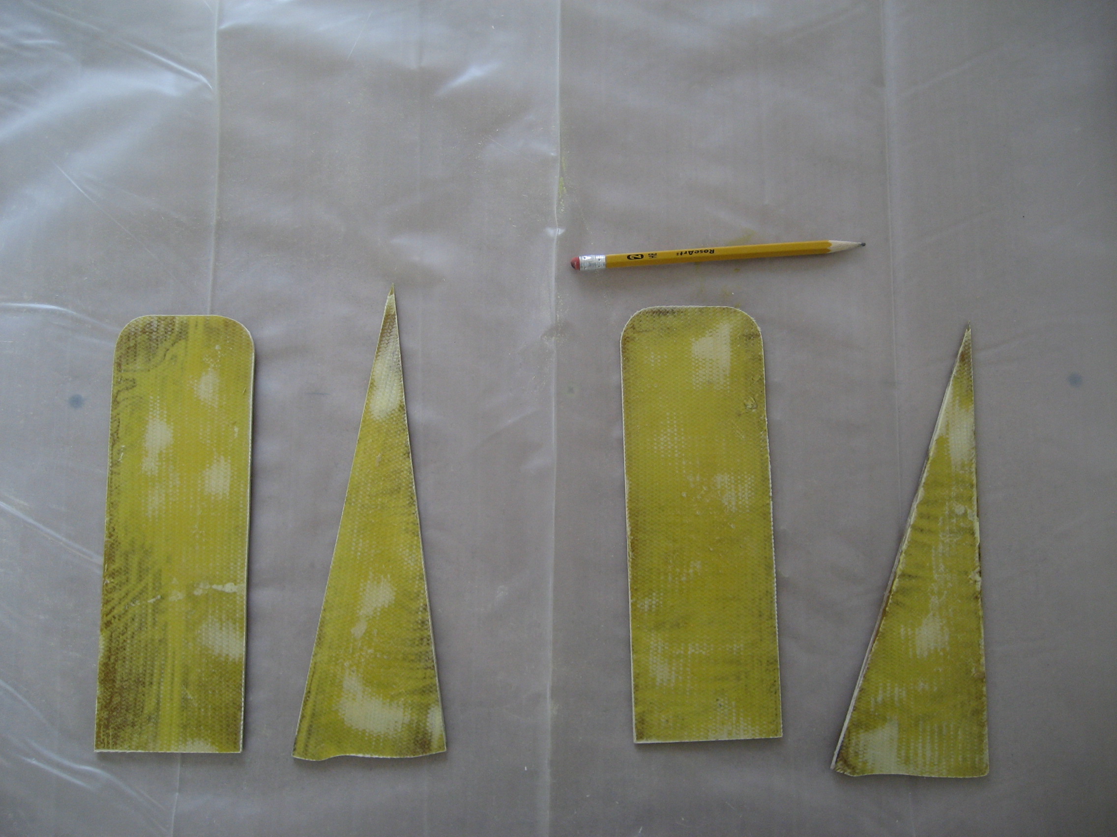
To prevent this from happening, two “guides” are made to keep the nose gear from rotating once it’s retracted. The guides are made by creating flat, 1/8″ thick layups and letting them cure. Then cutting them out and attaching them to create the guides.
Once the layups cured, I cut out the guides and supports for the left and right.
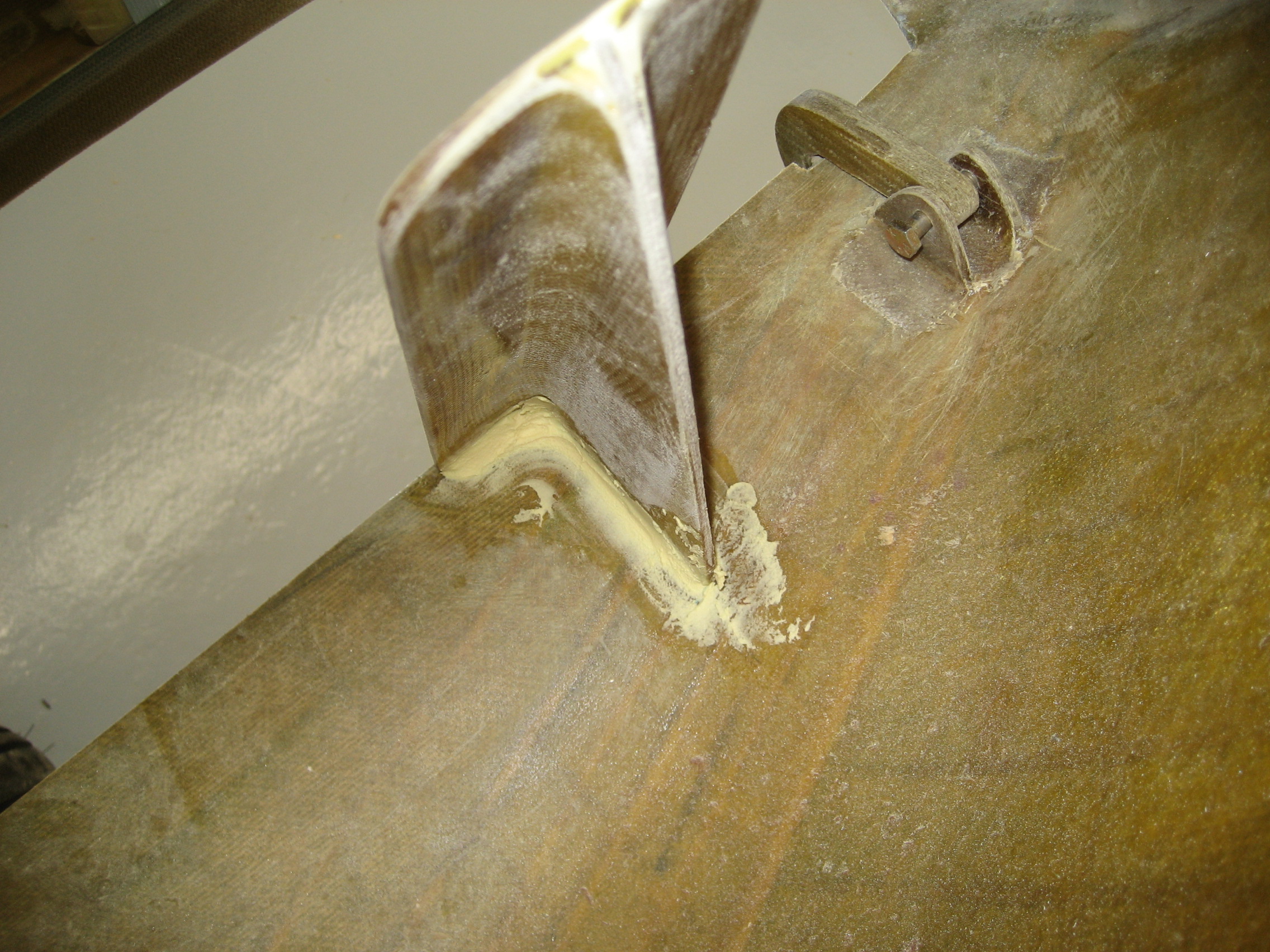
Then the supports are attached to the guides with 5-minute epoxy. When that sets up 2 BID layups are used to permanently attach the supports to the guides.


Once those layups cure, they’re trimmed and then the guides are fitted to the opening in the nose with 5-minute epoxy. When that cures, a radius is created with micro and 2 BID attaches the guides to the fuselage.


Trimmed and ready to go.
 .
.