
- 4.2.8 Battery Shelf
- 4.2.8 Battery Tray
- 4.2.3 Main Gear Bulkhead
- 4.2.9 Landing Lights
- 4.2.9 Landing Lights
In the manual, this is listed under “Fuselage”. But I’m doing things a little differently.
The Velocity comes with a single landing/taxi light mounted in the nose. Currently, the light that comes with the kit is a halogen light. They’re working on an HID (Xenon High Intensity Discharge) upgrade. HID lights are used some of the newer cars today. These are the really bright lights that have a bluish tint. They are extremely bright.
I want to put these in either the main wingtips or the ends of the canard for a couple of reasons:
1) More light. There’s no such thing as too much light when you’re landing at night.
2) Visibility… As in being seen.
When you’re flying, you are responsible for making sure you don’t run into another airplane. You’d be amazed how hard it is to see another airplane sometimes. I’ve been flying on an IFR flightplan when ATC advises me of another aircraft nearby sometimes as close as 3 miles and I never saw it.
I was flying into Dekalb (KDKB) one day and saw a pair of flashing lights in the distance. It was an airplane MILES away that was inbound for landing!!! After it landed, I spoke with the owner who told me that he had recently installed HID lights in the wingtips and added a pulsing system and made the lights flash in an alternating pattern.
So this a modification that I want to make.
Since the ends of the main wing are where the winglets attach, I decided that I didn’t want to weaken the structure there. So I went with the canard tips. First I would have to cut openings where I could recess the lights. In order to do that, I needed the lights to know how big an opening I would need. Some builders use the lights from a car but I needed really small lights that would fit in the canard and I wanted to stick with aircraft grade components. So I bought a pair of lights from Xevison.

Now that I’ve got the lights, I can layout the cut lines on the canard and make the cut. Once again, it makes me really nervous cutting into an airplane. Once I had the canard skin cut, then I just had to remove the foam.
I needed a way to mount the lights securely that would also allow me to remove them for maintenance. So I cut a pair of small aluminum angle brackets for each light.
Cutout for bracket.

Inboard bracket glued in place.
Both brackets glued in place for right light.
Next I covered the foam with BID and epoxy. Once that was done, I drilled a hole in each bracket and tapped in for 4-40 screws.
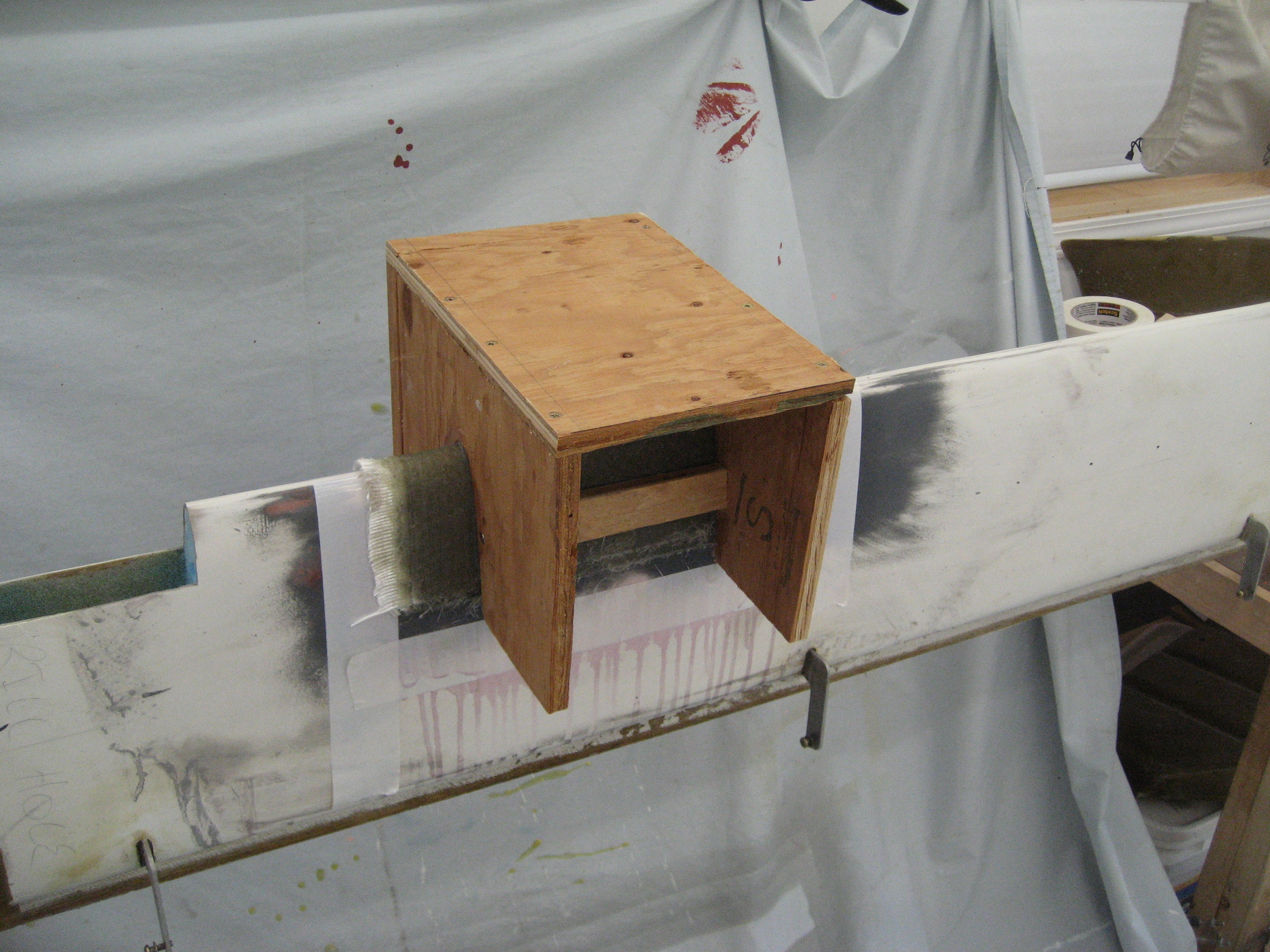
The lights will need a plexiglass cover. To be aerodynamic, it will need the same contour as the canard. To make these, I need a mold of the canard so I can make the lens cover.
The first step is to cover the canard with a release agent so the polyester resin that I use to make the mold doesn’t become a permanent part of the wing.
Section of the canard with the release agent applied.

The mold is made by applying two layers of fiberglass mat with a polyester resin. Polyester resin is used instead of epoxy because the heat from the heated plexiglass would cause the mold to deform if epoxy resin is used.
After the two layers of mat come one layer of BID, two layers of triax, one layer of bid and two layers mat. One of the challenges is keeping everything cool. Polyester resin can get very hot when curing. And the more you use, the hotter it gets. So I spread out the layers over a whole day and used a fan whenever the area started getting too warm.
Just about done.
Once the resin cured, I needed to build a stand for the mold. The stand also adds some structure to the mold.
Lens mold with stand.
The release agent is water soluble. So to remove it, I flipped the elevator over so that the mold was on the bottom. Then I used a spray bottle and squirted water around the mold/canard. After a few minutes and a little persuading, the mold fell right off the canard.
The final product.

A perfect shape.

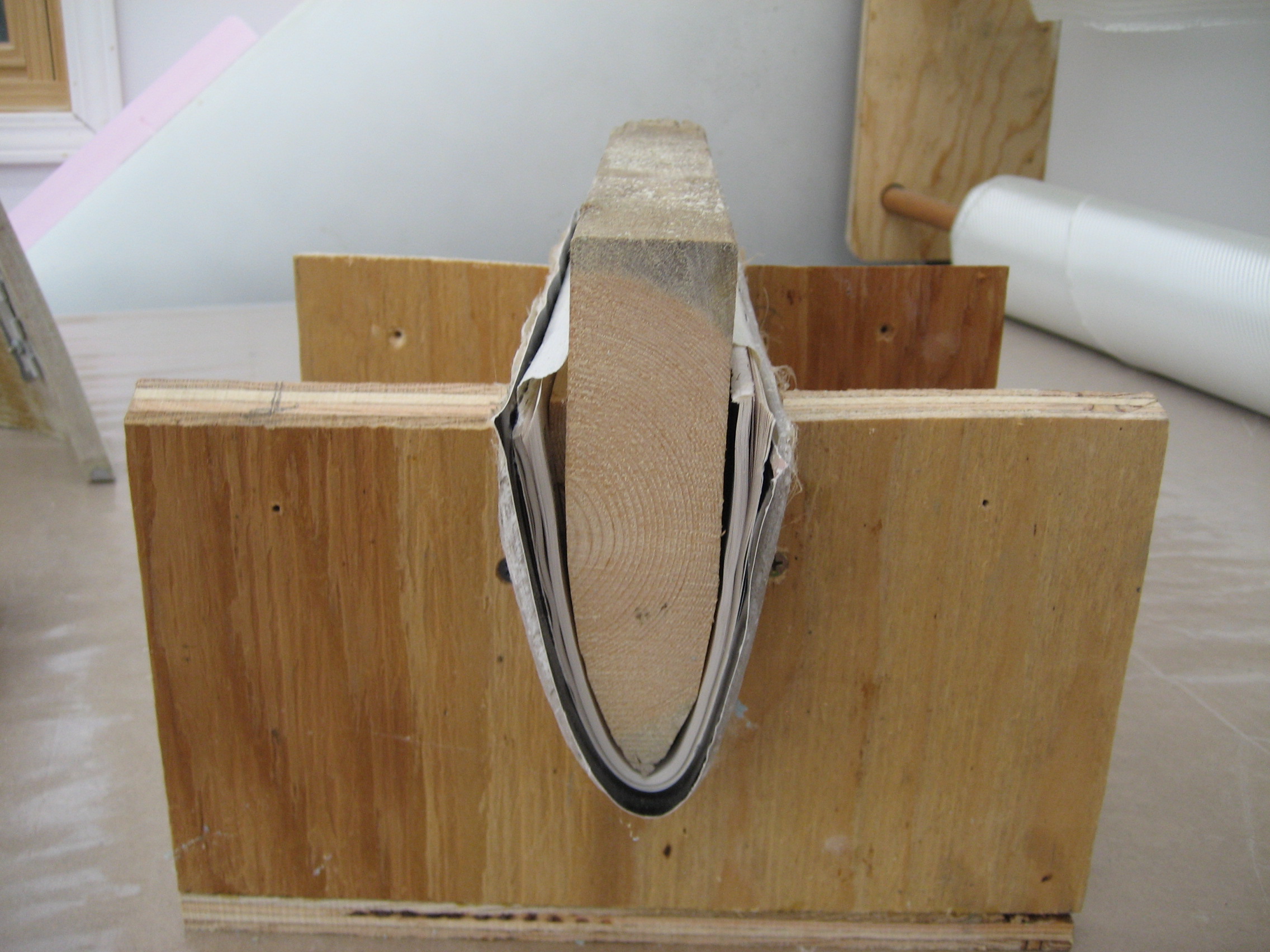
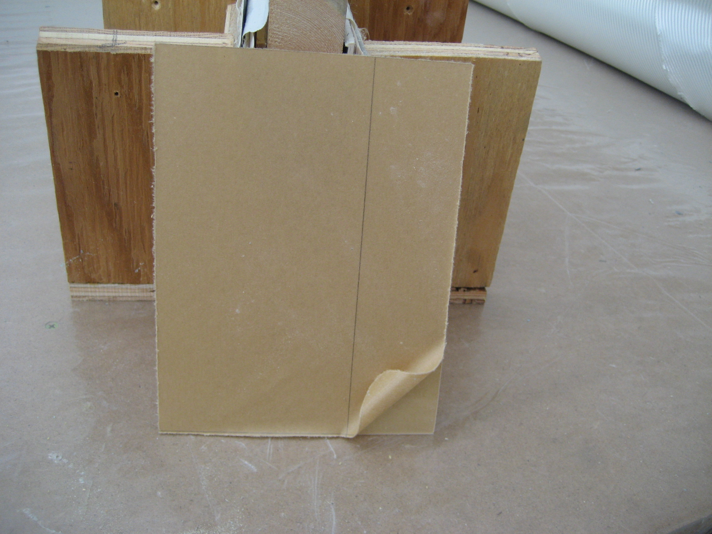
To get the plexiglass in the correct shape, I need a way to force it out at the top. Otherwise it’ll curl in. So I took a scrap piece of 2×6 and planed it to the right shape.

There are some slight imperfections in the mold and the inside piece is far from the correct shape. I solve this problem with an old Aircraft Tool Supply catalog.

The slick paper makes for a perfect release material and the rest of the catalog smoothes the shape of the inside mold.
Ready for the Plexiglass.
Next it was time to make the lenses. I obviously need one for each light, but while I making them, I may as well make a couple spares. I also need an extra one that I’ll cut in half so I can make the flanges that the lens will attach to.
So I got some 3/16″ plexiglass from McMaster-Carr and cut it to about 8″x8″. The actual lens will be a bit smaller, but since there’s no way to precisely position the plexi when you’re forming it, it needs to be larger than necessary so you can trim it to the correct size.
8×8 piece of plexiglass with the protective paper still on. The paper protects the surface from scratches until you’re ready to use it.
To make the lens, I’ll heat the plexi to about NO MORE than 370 degrees. I’ll start at 340 and move up as needed. I took a piece of coat hanger wire and made a hook for the top of the oven. Then I got a steel spring clip and attached it to one end of the plexi. Once the oven is preheated, I hang the plexi in the oven.
I know it’s at the correct temperature when I can poke the bottom of the plexi and it moves easily. Then I QUICKLY pull the plexi from the oven, bend it in two and drop the inside of the form in.
But there’s a slight problem. By the time I get the plexi out of the oven and in the mold, it’s already too firm to fully contour to the mold. I try a couple more times and end up putting the mold on the open oven door to reduce the time from the oven to the mold. I got a couple pretty good lenses but not good enough.
So I had to recruit my wife. With me positioning the soft plexiglass over the mold and her pushing the inside form in place, we were cranking out perfect lenses every time. Then, I just had to trim them to the correct size.

I took one of the lenses and cut it in half lengthwise. I taped the top half in place and, working from the inside used epoxy/flox/cabo to create a flange (lip) for the lens to rest on. Once it cured, I removed the lens half and taped the bottom half in place the finished the bottom flange.
half lens in place with flange

light opening with lens flange
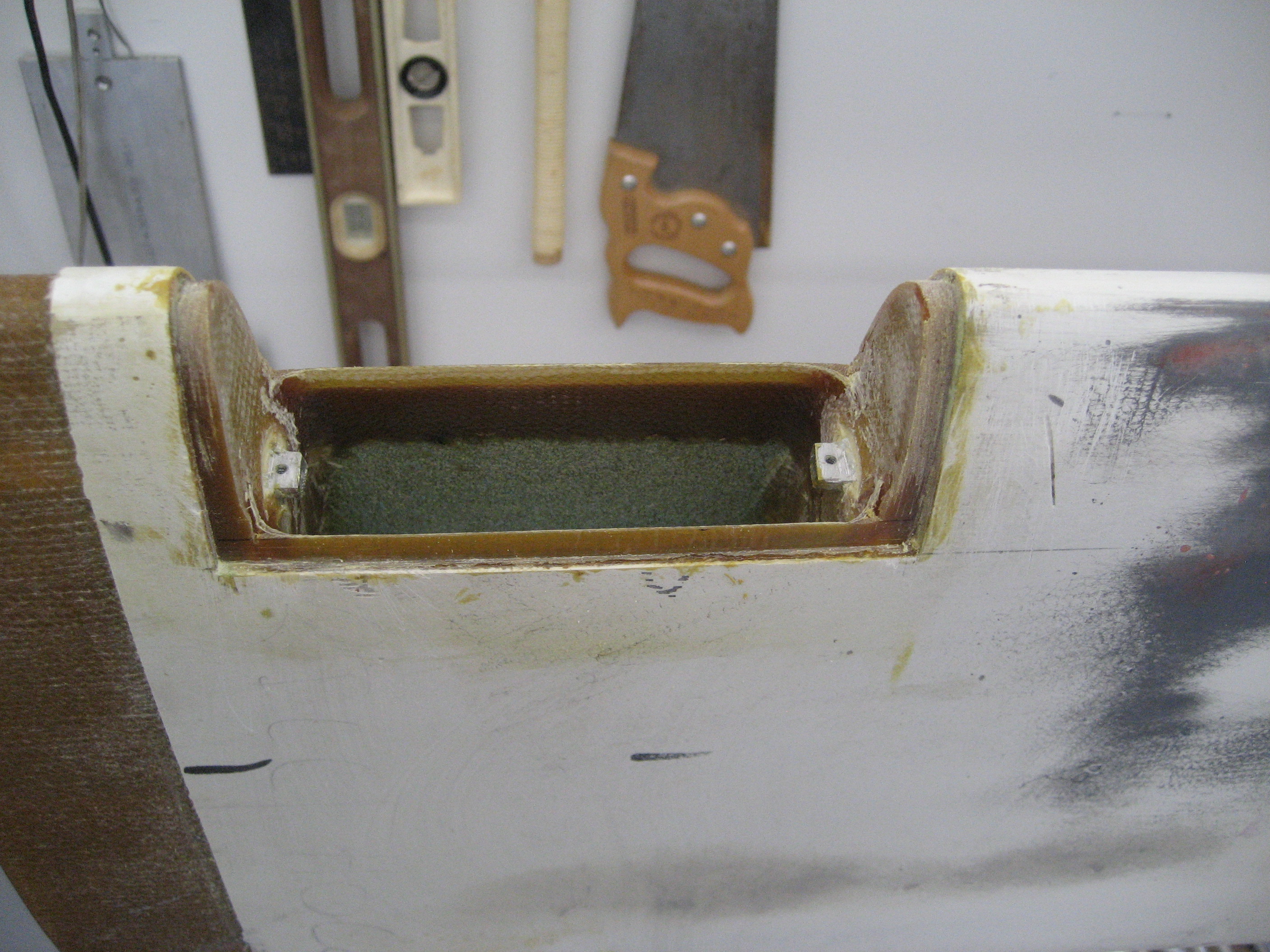
With the light installed.
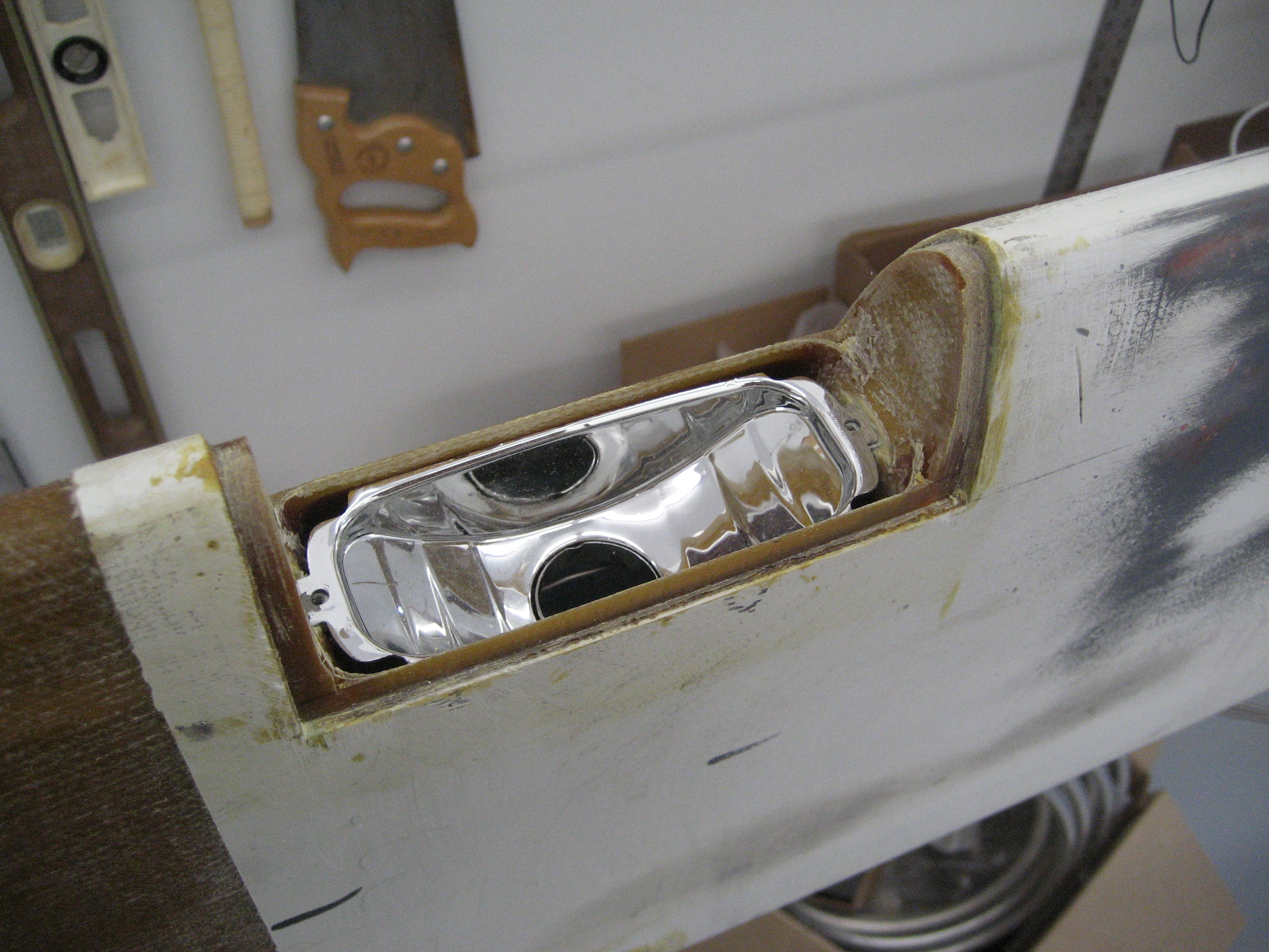
Test fit of the final result. I’m leaving the bulbs out so as not to break them.