
- 6.5.2 – Rudder Pedals
- 6.7.1 – Spar Positioning
- 6.1.5 Keel Hardpoints
- 6.8.1 – Canard Reinforcements
- 6.1.3 Keel Access Holes
- 6.2.3 Front Seats
- 6.3.1 Assemble Rudder Pedals
- 6.3.1 Brake Lines
- 6.3.1 Brake lines
- 6.3.1 Brake Lines
- 6A.3.1 Toe Brakes
- 6A.3.1 Parking Brake
- 6.6.2 – Install Landing Gear Selector
- 6.2.2 Safety Harness Hardpoints
- 6.9 Overhead Fresh Air Plenum Modification
- 6.9 Overhead Fresh Air Plenum Installation
- 6.3.7 Keel Installation (prep)
- 6A.3.1 Rudder Pedal Assembly
- 6.3.7 Keel Installation
- 6.7.2 Main Spar Installation
- 6.7.3 Main Spar Triax Layups
- 6.2.1 Seat Hardpoints
- 6.1.2 Keel Access Cover Flanges
- 6A.3.1 Rudder Pedal Installation
- 6.6.2 Install Instrument Panel
- 6.2 Assemble Seats
- 6.8 Doghouse Edge Finishing
- 6.8 Canard Reinforcements
- 6.8.2 Doghouse Attach Points
- 6.5.4 Install Nylaflow Tubing for Rudder Cables
- 6.3.7 Install Aft Keel Section
- 6.9 Overhead Plenum Lights
- 6.0 Aft Carbon Beam (Remediation)
- 6.9 Overhead Fresh Air Plenum
- 6.9 Overhead Fresh Air Plenum Painting
- 6.0 A-Pillar Beam (Overhead Switch Panel)
- 6.3.2 Front Seat Assembly
- 6.3.2 Front Seat Rails
- 6.3.2 Seating modifications
- 6.2.2 Safety Harness Replacement
- 6.2.2 Safety Harness Replacement
- 6.3.2 Seat rails and hardpoints
Here you can see the duct for the fresh air in between the two engine cooling NACA ducts.

On the inside, there’s a plenum that runs from the rear up to the front. I’m going to install four eyeball vents (one for each seat) and four lights. The electrical lines for the lights will also be in the plenum. Determining the location of the vents and lights will be a little tricky since the seats aren’t in and the airplane is upside down so I’ve got to guesstimate their location.
Here’s one of the vents that I’m going to be using.

I forgot to get a picture of the plenum before cutting the holes for the lights and vents. But here’s the front of the plenum after the holes are drilled for the vents with one of the vents installed.

Here it is mounted in the plenum.

Oops. Going to need to be modified. 🙂
Before and after.

Here’s the plenum with the openings for the vents, lights and switches.

The plenum with the vent, light and switch for the left rear seat.

Closeup of the previous position.

The lights are attached with 4 6-32 screws so I had to drill holes for the screws and nutplates.

Can’t leave well enough alone. After talking with my A&P (Airframe and Powerplant mechanic) who used to work for United keeping their airplanes flying, he suggested an “all on” switch. A single switch that will turn on all the lights. Sounded like a good idea but it will require redesigning the lighting circuit board. This time, I decided to let the company that provides the design software make the board. It cost about $10 per board so I figured that I would try it. While I was at it, I added a fourth white LED and used a single resistor for both sets of lights.
Here’s the new circuit board.

Mounted and wired.

From the inside.

Test run.

More Plenum Work
Because the air intake is on the top of the fuselage, water will be able to enter the plenum. So a drain is needed at the back of the plenum.

Then I put a bulkhead just aft of the drain so no water would pool in the plenum.

Finally, to prevent water from being forced up front and out the vents, I installed a small “half bulkhead” (a dam, if you will) between the intake and the vents up front.

I was going to add the swivel map light at the front of the plenum. This would illuminate the overhead switch panel and could be used for a map light. For some reason, I decided to check the location. Good thing I did…

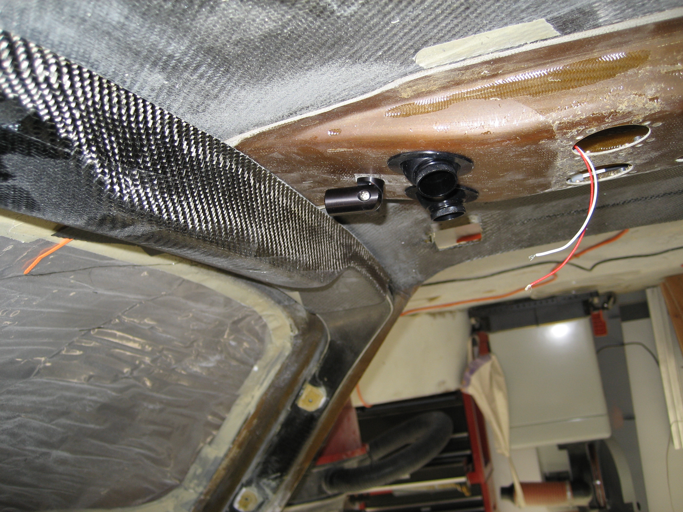
Two things wrong here: 1) it’s so close to the panel that it would only be able to illuminate a fraction of the panel and 2) it will interfere with accessing the switches. So it I decided to move it to the side and a couple inches back. While it won’t light the panel like I thought, I can still use it as a map light.
Before installing, I still need to paint it.