
- 13.4.3 Pitot Tube Installation
- 13.4.2 Static Port
- 13.2.1 Instrument Panel Mounting
- 13.3.2 Ground Power Plug
- 13.0 Electrical System Documentation
- 13.0 Wire Labels
- 13.2.2 / 13.6.2 Aft wiring complete
- 13.8.1 Magnetometer connections
- 13.9.2 Autopilot Roll Servo Wire Routing Modification
- 13.7.1 Avionics Shelf
- 13.8.1 Magnetometer Mounting Bracket – Completed
- 13.8.1 Magentometer Bracket
- 13.1.6 Transponder Antenna Ground Plane
- 13.5.1 Navigation/Strobe Wing Root Connectors
- 13.0 Electrons are flowing
- 13.9.2 Autopilot Roll Servo Mounting
- 13.3.4 Overhead Switch Panel Wiring
- 13.2.2 Engine Wiring
- 13.6.2 Primary Alternator Connection
- 13.7.1 Avionics Shelf
- 13.8.1 OAT probe
- 13.2.2 EIS wiring
- 13.2 EFIS and Instrument Panel Layout
- 13.6 Ground Block – Part II
- 13.7.4 Headset jacks
- 13.3.4 Overhead Switch Panel
- 13.6 Ground blocks
- 13.8.2 Annunicator Panel
- 13.8.2 Annunicator Panel
- 13.8.2 Annunicator Panel
- 13.6 Electrical supply lines
- 13.6.3 Ground Power Receptacle
- 13.2 Instrument Panel Layout
- 13.3.5 Avionics Wiring
- 13.9.2 Auto Pilot Pitch Servo Mounting
- 13.7 Avionics and Wiring
- 13.7 Wiring
- 13.2 Panel painting
- 13.2 Panel installation
- 12.3.5 Minor setback on Avionics wiring
- 13.8.2 Annunciator Panel Problem
- 13.1.9 ELT Installation
- 13.6 Power Supply
- 13.7.4 It’s always something…
- 13.0 Wire routing
- 13.1.8 GPS Antenna Shelf
- 13.7.4 Audio Panel Relocation
- 13.0 Wire Routing (Remediation)
- 13.6.1 Battery Hold-Down
- 13.2.1 Instrument Panel – Final Install
- 13.3.3 / 13.5.3 Trim & Landing Light Test
- 13.8.1 EFIS alternate power
- 13.5.2 Cabin Lighting
- 13.1.4 Glideslope Antenna
- 13.3.4 Overhead Switch Panel
- 13.99 Instrument Panel overlays
- 13.99 Installing Engraved parts
- 13.99 Instrument Panel Lighting
- 13.4 Pitot/Static Remediation
- Static Port Conundrum
- GPS Replacement
- Secondary EFIS Power
- 13.99 Electrical System Diagram
- 13.99 – Current Sensor Repair
- 13.99 – ADS-B in antenna
- 13.99 – Switch panel update
- 13.4 – More Static Port Fun
First I built my overhead courtesy lights. Click here for a refresher. I even etched my own circuit boards.
Then I decided to add an “all on” feature which required a circuit board redesign. For version 2, I had the circuit boards etched by a company that specializes in that work.
Then I decided that I wasn’t happy with my dimming choice. There’s a good chance that I’ll want to dim these lights. My plan was to connect a potentiometer (variable resistor) to the supply side. But LED’s are weird little ducks. With incandescent lights (24 volt, for example), they begin to glow with about 1 volt and get brighter with increasing voltage up to 24 volts. So to dim incandescent lights, you connect a pot (short for potentiometer) that allows you to adjust the voltage going to the lights. This works just like the dimmer in your house.
But like I said, LED’s are different. First, they’re current driven instead of voltage driven. But to keep things simple, we’ll approach this from the voltage side. The second (and this is what caused my current problem) is there operating range. The LED’s I chose were 3 volt LEDs (I reduced the voltage to the LED’s using a fixed resistor). But here’s where the dimming problem came in. These LED’s don’t start to light until about 2.4 volts. So with the pot installed, you turn it and nothing happens for the first 3/4 of a turn and then the slightest movement of the knob causes a huge difference in brightness for the remaining 1/4 turn.
So I had to educate myself with how to power and dim LED’s. So I started looking for dimmers. I found a guy that makes a bunch of stuff for the experimental aircraft market. He makes a dimmer called EGPAVR (Extraordinarily General Purpose Adjustable Voltage Regulator). With it, you can define the lower and upper voltage levels for your lights. So I picked up a couple and started testing my new design. One other modification I made was to increase the number of LED’s in each fixture. You can always dim or turn them off, but you can’t make them brighter than max brightness.
Here’s my test setup. The LED’s are on the breadboard. The EGPAVR is to the right. A variable resistor used to determine the fixed resistor values is to the right of the EGPAVR and I have two meters to monitor the voltage and current levels.


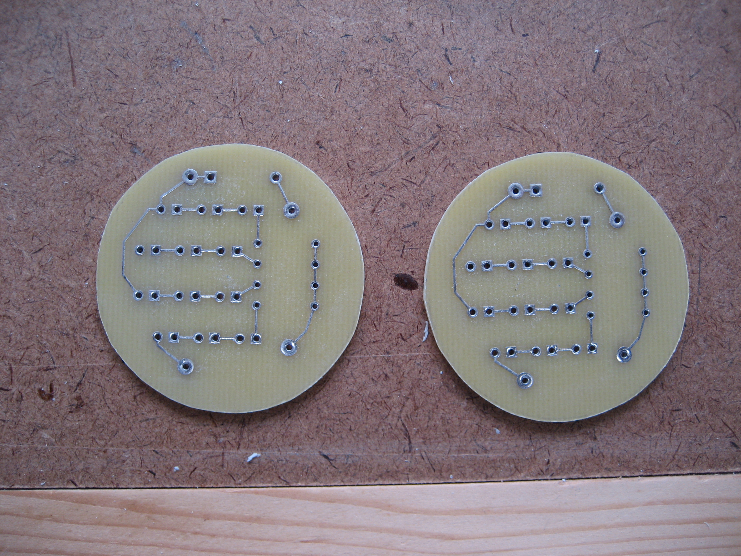
Once I had the values for the fixed resistors determined, I designed my new circuit boards and sent them to be etched. When they came in, I disassembled the old lights and got to work.
The new PCBs

Each card and circuit boards for two light fixtures.
Marked for cutting.

And after cutting.
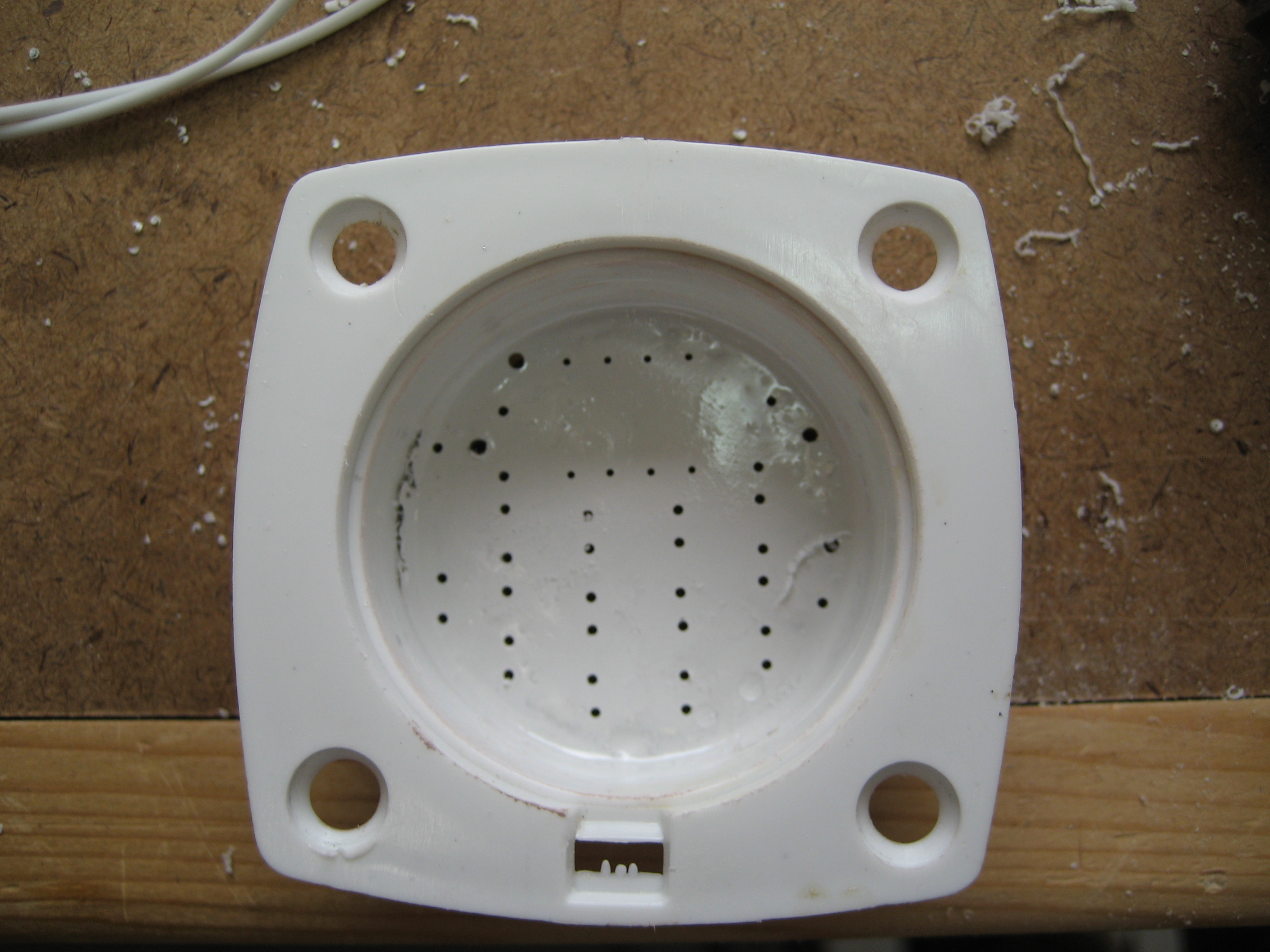
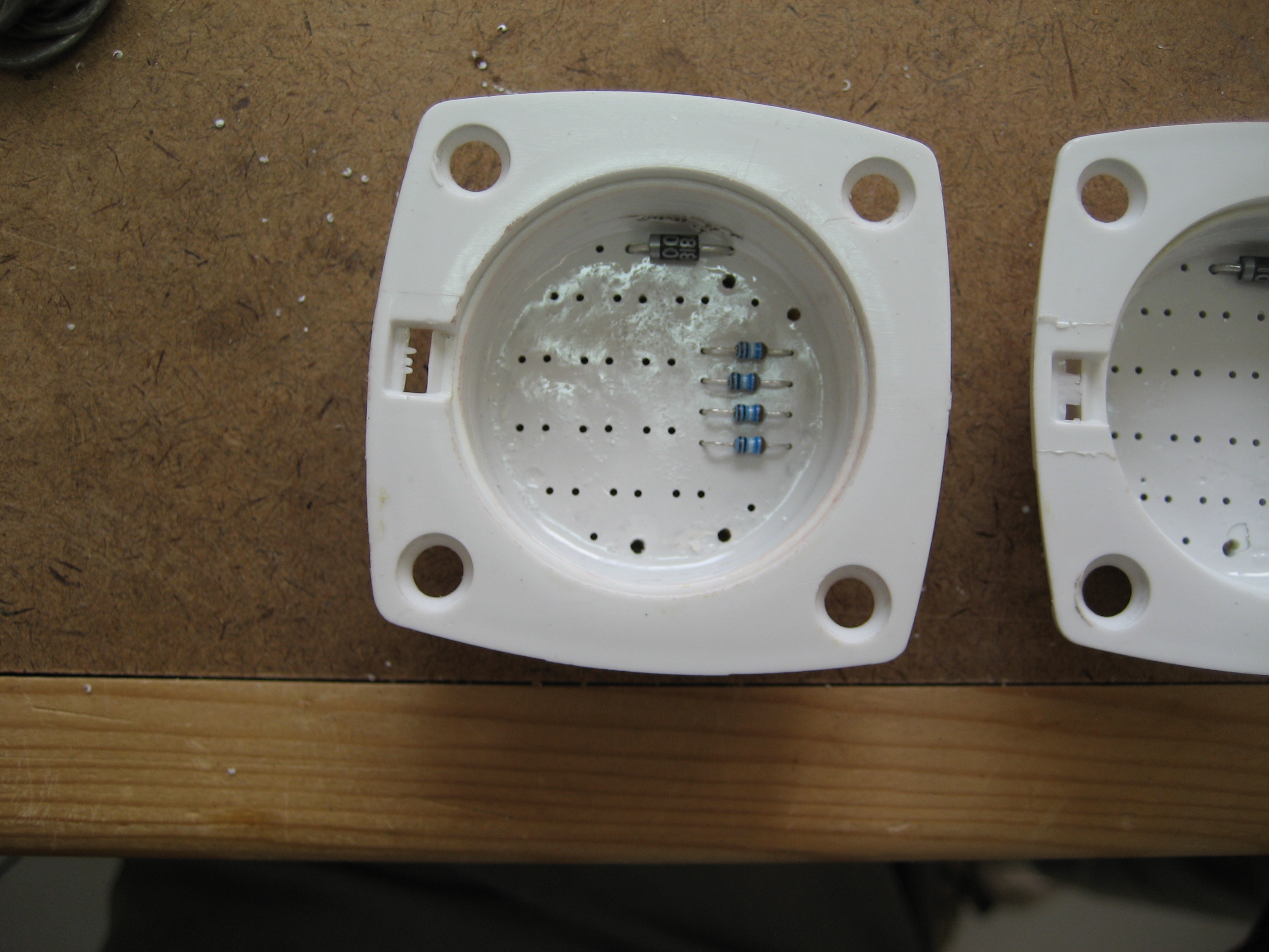
Here the light fixtures ready for assembly.
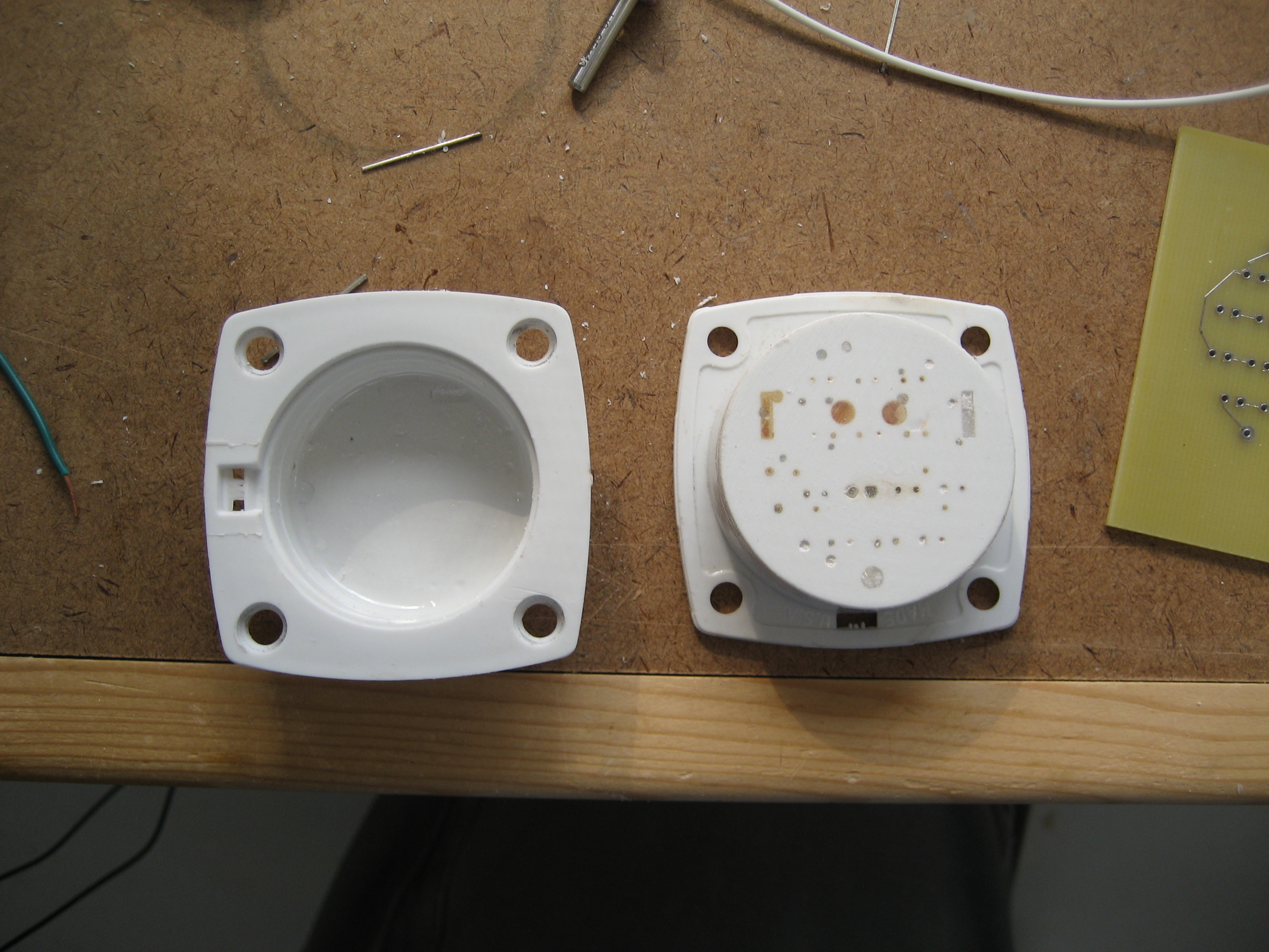
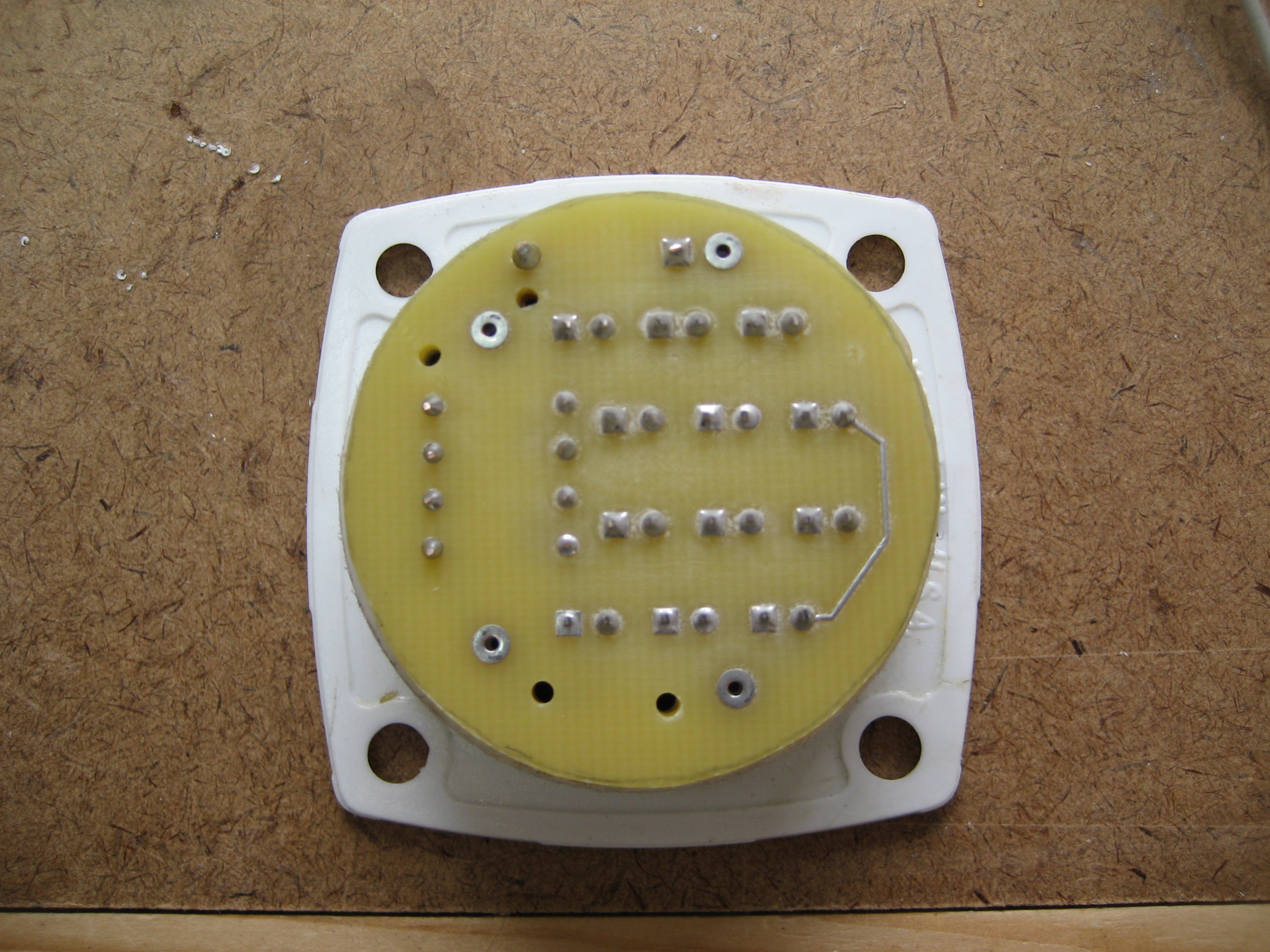
Circuit boards have been mounted to the back and holes drilled.
Resistors and diode inserted.
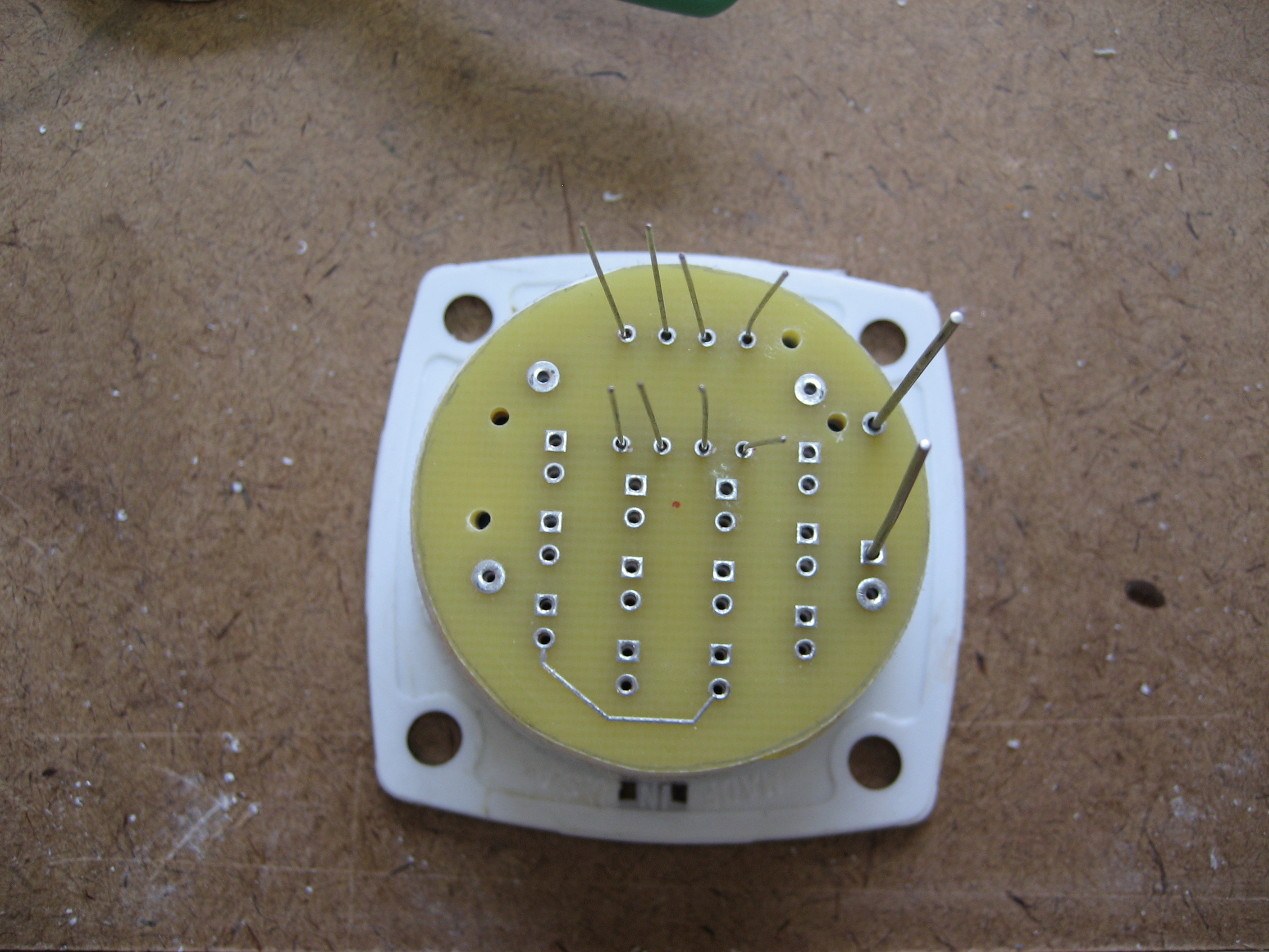
LEDs mounted.
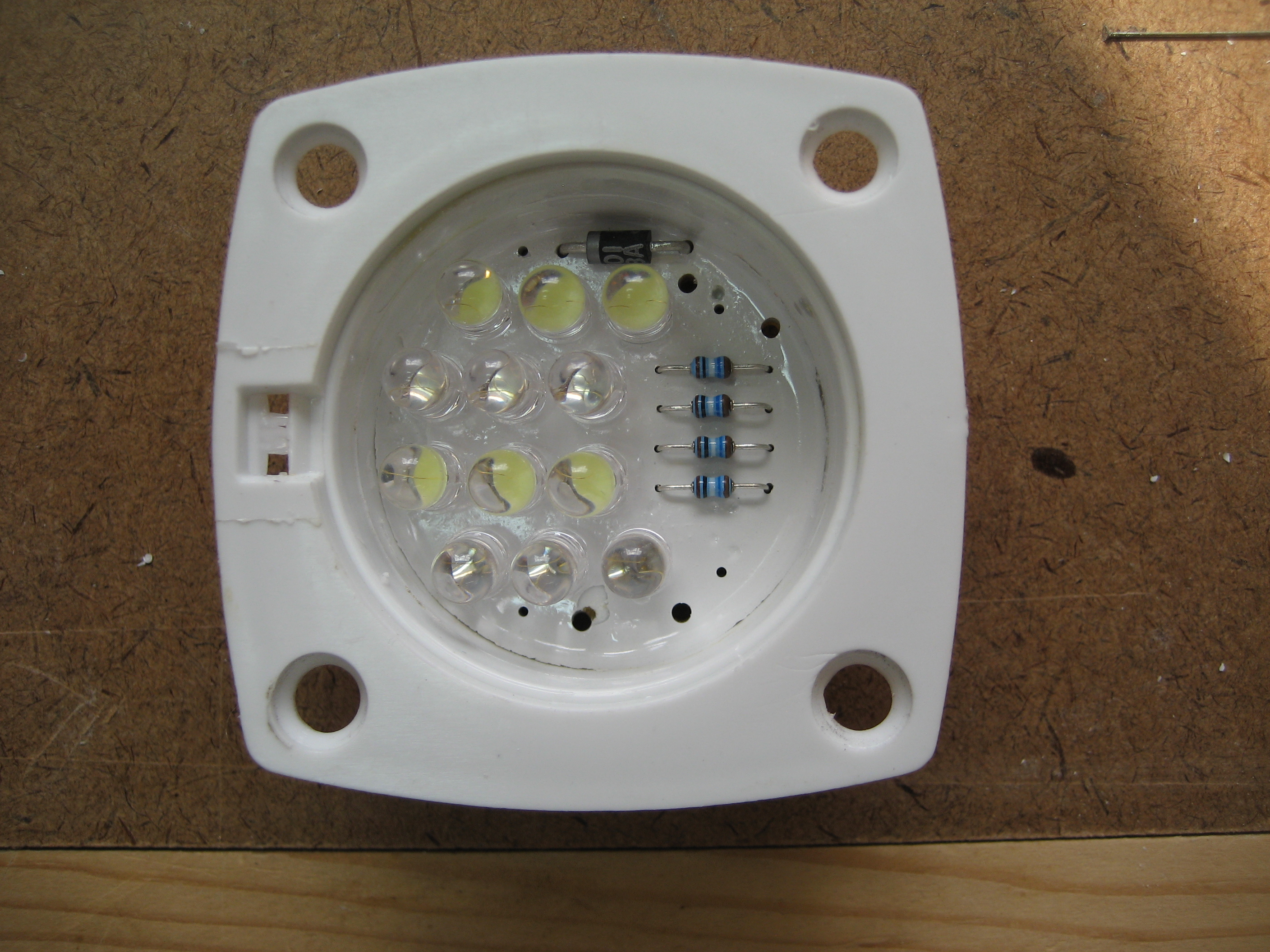

And finally the wiring harness and connector installed
