
- 13.4.3 Pitot Tube Installation
- 13.4.2 Static Port
- 13.2.1 Instrument Panel Mounting
- 13.3.2 Ground Power Plug
- 13.0 Electrical System Documentation
- 13.0 Wire Labels
- 13.2.2 / 13.6.2 Aft wiring complete
- 13.8.1 Magnetometer connections
- 13.9.2 Autopilot Roll Servo Wire Routing Modification
- 13.7.1 Avionics Shelf
- 13.8.1 Magnetometer Mounting Bracket – Completed
- 13.8.1 Magentometer Bracket
- 13.1.6 Transponder Antenna Ground Plane
- 13.5.1 Navigation/Strobe Wing Root Connectors
- 13.0 Electrons are flowing
- 13.9.2 Autopilot Roll Servo Mounting
- 13.3.4 Overhead Switch Panel Wiring
- 13.2.2 Engine Wiring
- 13.6.2 Primary Alternator Connection
- 13.7.1 Avionics Shelf
- 13.8.1 OAT probe
- 13.2.2 EIS wiring
- 13.2 EFIS and Instrument Panel Layout
- 13.6 Ground Block – Part II
- 13.7.4 Headset jacks
- 13.3.4 Overhead Switch Panel
- 13.6 Ground blocks
- 13.8.2 Annunicator Panel
- 13.8.2 Annunicator Panel
- 13.8.2 Annunicator Panel
- 13.6 Electrical supply lines
- 13.6.3 Ground Power Receptacle
- 13.2 Instrument Panel Layout
- 13.3.5 Avionics Wiring
- 13.9.2 Auto Pilot Pitch Servo Mounting
- 13.7 Avionics and Wiring
- 13.7 Wiring
- 13.2 Panel painting
- 13.2 Panel installation
- 12.3.5 Minor setback on Avionics wiring
- 13.8.2 Annunciator Panel Problem
- 13.1.9 ELT Installation
- 13.6 Power Supply
- 13.7.4 It’s always something…
- 13.0 Wire routing
- 13.1.8 GPS Antenna Shelf
- 13.7.4 Audio Panel Relocation
- 13.0 Wire Routing (Remediation)
- 13.6.1 Battery Hold-Down
- 13.2.1 Instrument Panel – Final Install
- 13.3.3 / 13.5.3 Trim & Landing Light Test
- 13.8.1 EFIS alternate power
- 13.5.2 Cabin Lighting
- 13.1.4 Glideslope Antenna
- 13.3.4 Overhead Switch Panel
- 13.99 Instrument Panel overlays
- 13.99 Installing Engraved parts
- 13.99 Instrument Panel Lighting
- 13.4 Pitot/Static Remediation
- Static Port Conundrum
- GPS Replacement
- Secondary EFIS Power
- 13.99 Electrical System Diagram
- 13.99 – Current Sensor Repair
- 13.99 – ADS-B in antenna
- 13.99 – Switch panel update
- 13.4 – More Static Port Fun
It’s time to start actually mounting avionics. I’ve held off as long as I could because once the avionics shelf goes in, getting to things gets harder.
Prior to receiving all the various boxes that go on the shelf, I used blue foam cut into the correct size and shape to determine where everything would go.

But now it’s time to start mounting things. Some builders will wire the components up on the bench first. But I couldn’t imagine running all the wiring for that temporarily.
Here’s the two comm radios and single nav radio. I made the brackets which combine the three radios into a single unit for mounting.

Then I added the transponder (which actually attaches to a mounting tray.

Next I put in the mounting tray for the FastStack wiring hub that all the boxes will connect to.

And finally the Audio Panel. The AHRS, VPX, and trim controller sub-shelf had already been mounted.

Then I installed the shelf into the plane to make sure everything still fit.

Now it’s time to start pulling wires.
The largest of the wiring assemblies were for the EFIS screens and the Audio Panel. So I put those in first since they have the largest bend radius.

One of the things I was worried about was the connectors for the EFIS screens. The extend towards the avionics shelf and I was worried about whether the installed avionics boxes would interfere with the connections. So I came up with a rather low-tech approach.
I cut a piece of card stock the size of the EFIS screens and cut out where the connectors would be. Then I taped some long stir sticks that ended on the panel mounting screws.

Then I just put the ends of the stir sticks on the panel mounting holes and I could see where the connectors would end up.

This confirmed that the connectors would not interfere with any of the existing equipment.
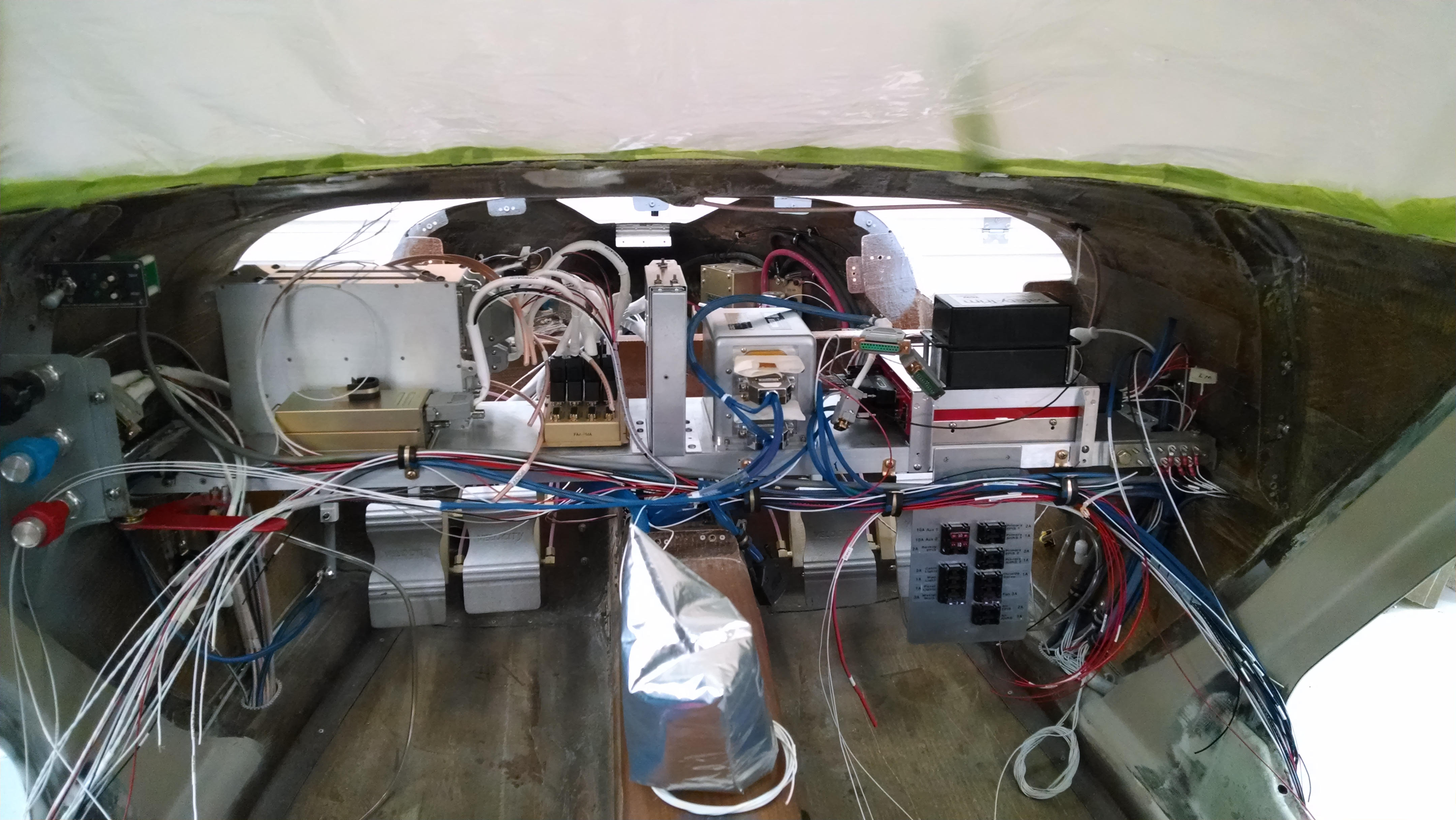
At this point it was time to start pulling the rest of the wires. The FastStack Hub greatly simplified the whole process. But even with that, there are still a bunch of wires.

After a while, it starts getting a little better looking. But still a long way to go.
I felt like I should make sure the panel cutouts for EFIS screens, switch panels and power ports were correct (I had checked them individually but not all at the same time). So I made a stand to hold the panel up and installed all the components.

The only thing left to do is mount the Backup EFIS.