- 12.1 Engine arrival
- 12.1 Engine Installation Prep
- 12.1 Engine Installation Prep
- 12.1.2 Engine Mounts
- 12.1.2 Engine Installation
- 12.2.1 Aluminun Oil Lines
- 12.2.1 Aluminum Oil Lines
- 12.2.1 Cabin Heat
- 12.2.2 Fuel Lines
- 12.2.2 Fuel Lines
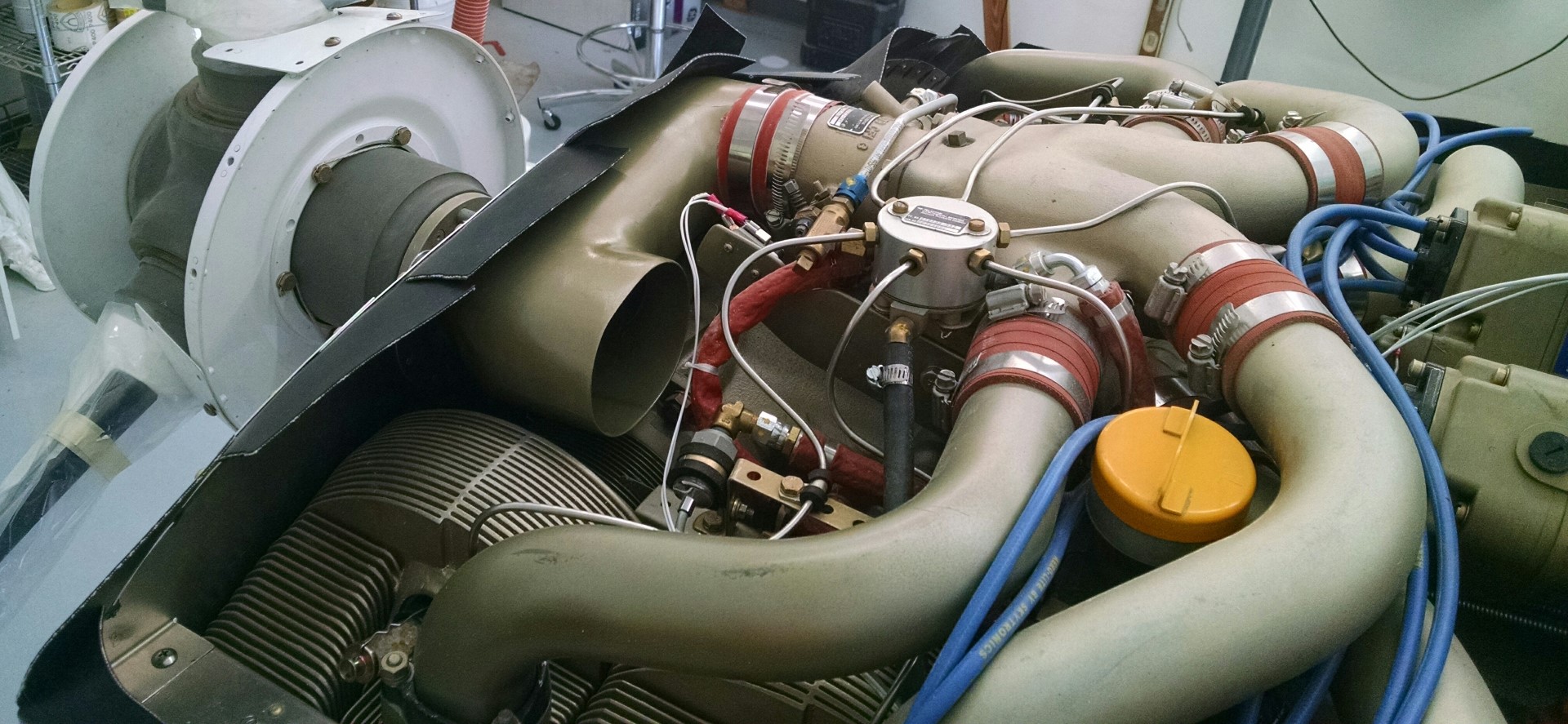
- 12.1.2 Intake tube modification
- 12.2.2 Fuel Lines
- 12.1.2 Intake tube modification
- 12.1.2 Intake tube modification (completed)
- 12.3.1 – Installing Throttle, Mixture, and Prop Controls
- 12.3.1 – Mixture Control Mounting Bracket
- 12.3.1 Prop Control Bracket
- 12.3.1 Throttle Control Bracket
- 12.2.3 Cylinder Intake Drain Lines
- 12.2.1 – Aluminum Oil Lines
- 12.3.4 Cooling Plenum
- 12.1.2 Oil Cooler mod
- 12.2.4 Pressure lines
- 12.3.4 Cooling Plenum
- 12.2.4 Pressure Lines
- 12.3.4 Cooling Plenum Intakes
- 12.2.3 Electric Fuel Pump Drain
- 12.2.3 Mechanical Fuel Pump Drain
- 12.2.3 Fuel Pump Drain Lines
- 12.2.3 Spider Drain Line
- 12.3.5 Propeller
- 12.4 Exhaust Installation
- 12.3.6 Nose Oil Cooler
- 12.3.6 Nose Oil Cooler Control
- 12.4 EGT Probe Installation
- 12.2.4 Oil Pressure Sensor (remediation)
- 12.4 Oil breather line
- 12.3.4 NACA duct extensions
- 12.4.2 Exhaust Fairing
- 12.3.6 Cabin Heat Damper Control
- 12.99 Induction Air
- 12.2.2 Fuel Line
- 12.3.6 Nose Mounted Oil Cooler
- 12.99 Engine Woes
- Engine Dehydrator
- Fouled injectors
- 12.99 – Oil temperature and heat challenges
- 12.99 Cabin Heat
- Electronic Ignition
- 12.99 Engine induction air
In a standard Continental IO550N installation, the way the engine gets air is through a “U” shaped duct that takes the rearward facing fuel injection servo and points the intake forward (remember the engine is in backwards). Since I’m going a different type of plenum, that part won’t work for me.
An added issue is that the air is pulled directly from the upper area (which is supposed to cool the engine as it is pulled down) and there’s NO AIR FILTER!
So I had this idea that I would make a NACA duct on the bottom, put an air filter down there and somehow create some ducting to get that clean air up to the top of the engine.
I started with the part that I thought would be hardest. Making the ducts to get the engine intake extended to the lower cowling.
So I used a trick that I learned from Malcolm for fast prototyping. Using some leftover blue foam, I made a slightly smaller version of the duct. Malcolm’s next door neighbor builds funny cars and has a lot of experience moving air to 1,000+ horsepower engines. He said that squaring off the outside radius of the turns improves the airflow. So I squared off the outside part of the turns.

The next step is to cover the foam with duct tape. But with the curves on this part, that didn’t work too well. So I used electrical tape instead. Because it’s softer, it was able to make the turns better. Then I smeared vasilene over the part and covered it with 4 layers of BID.
Once the epoxy cured, I poured acetone through the part which dissolves the foam. Then you just remove the tape and you’ve got your part.
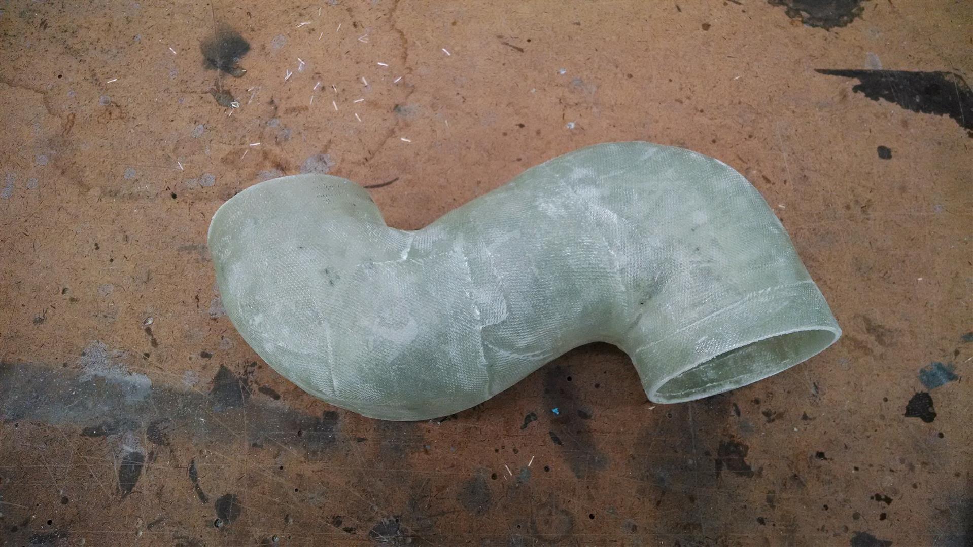
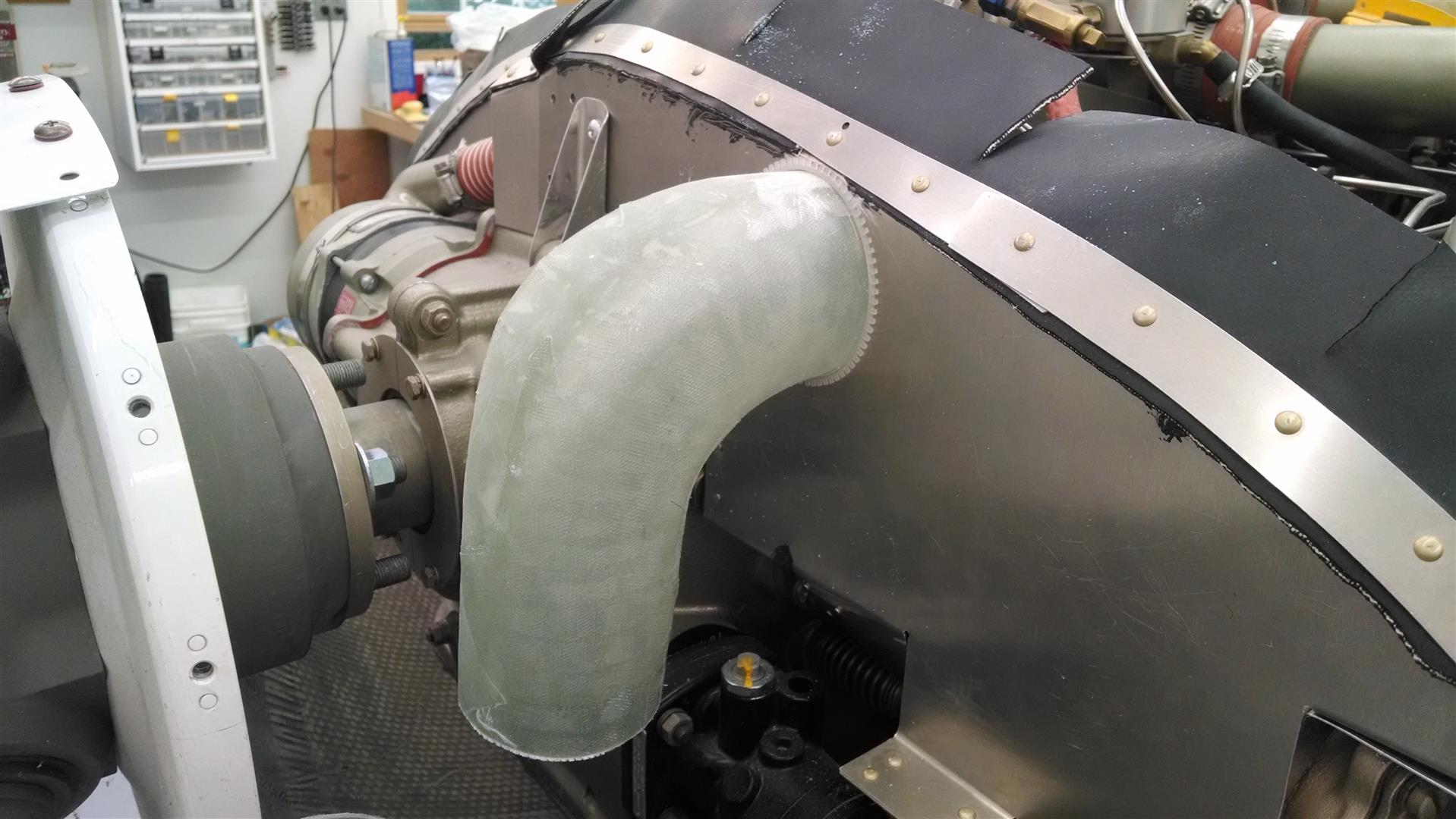
The next part is the elbow to turn towards the lower cowling. By comparison, this is an easy part to make. Once again, I squared off the outside radius.
Then I cut a hole in the aft baffle and joined the two parts with a friction slip-joint. I added a tab to assure it would stay in place.

All in all, I was feeling pretty good.
I picked up a 11″x6″ K&N generic air filter from the auto parts store, measured it and (this time) used plywood to make the mold for the filter box.
This would connect to the NACA on the lower cowl. Then I would make some ducting to get the air up to the elbow.
And that’s when I figured it out… There’s just no room! The amount of space between the engine (and engine mount) isn’t big enough to allow for a submerged NACA. Let alone the almost 4 feet of ducting to get it up to the engine. I spent a lot of time researching various solutions but I just couldn’t figure out a way to make it work and not lose any performance.
So I had to drop back and punt. I made a U and I’ll pull air from the upper plenum without a filter. 🙁


I went ahead and painted it so at least it looks pretty.