9.0 Strakes

This entry is part 9 of 18 in the series 09 - Fuel System

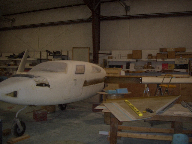
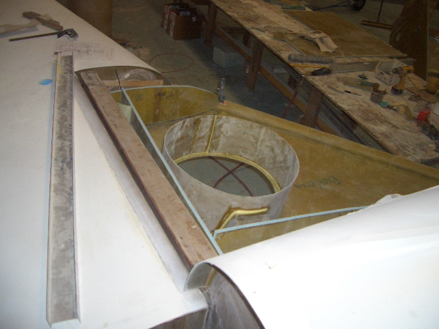
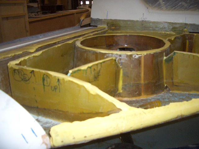
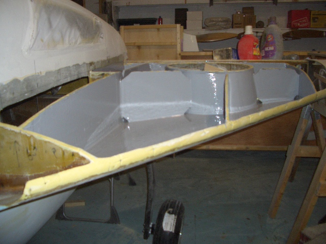
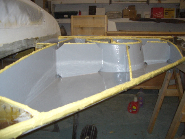
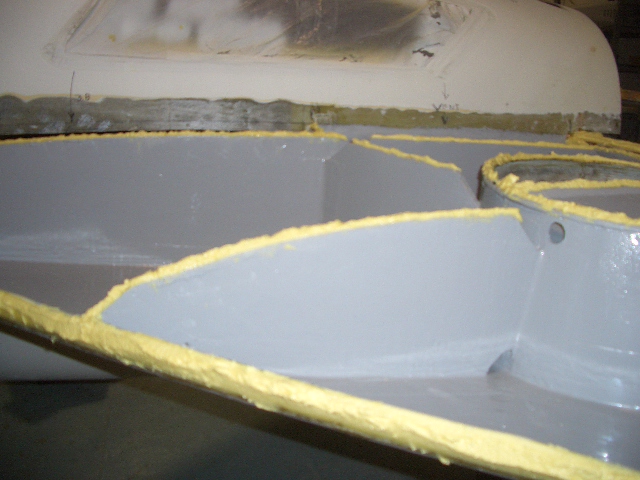
It’s time to build the strakes. It’s kind of hard to describe the strakes so I’ll use visual aids.

Here’s the top view of the fuselage.
VelocityTopView3
At the rear is the center spar extending out the sides. The main wings will attach to this spar.
Here it is with the wings attached.

VelocityTopView5
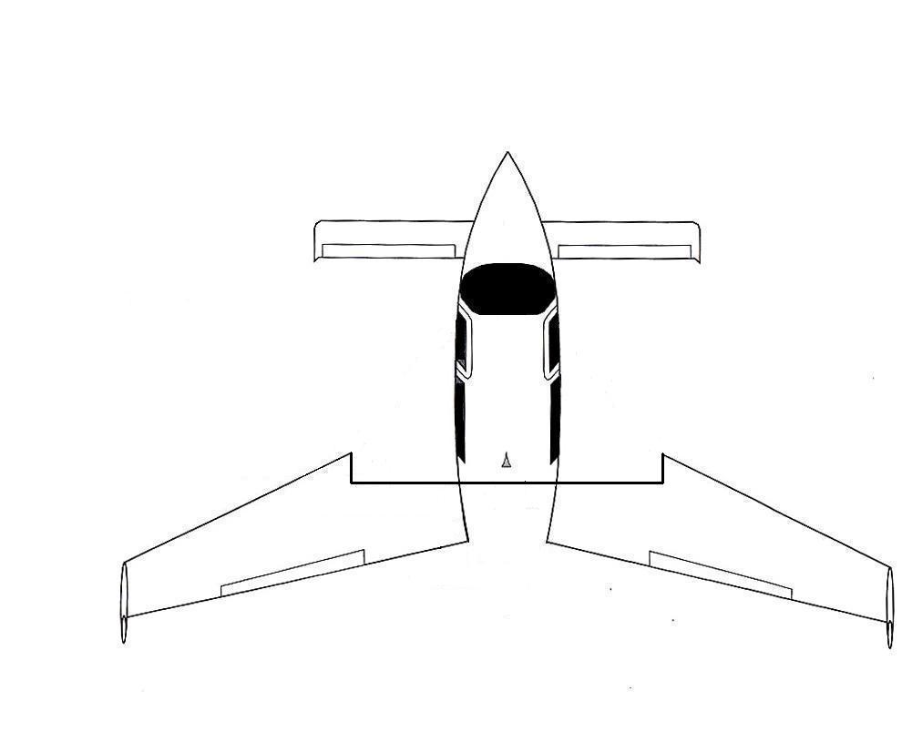
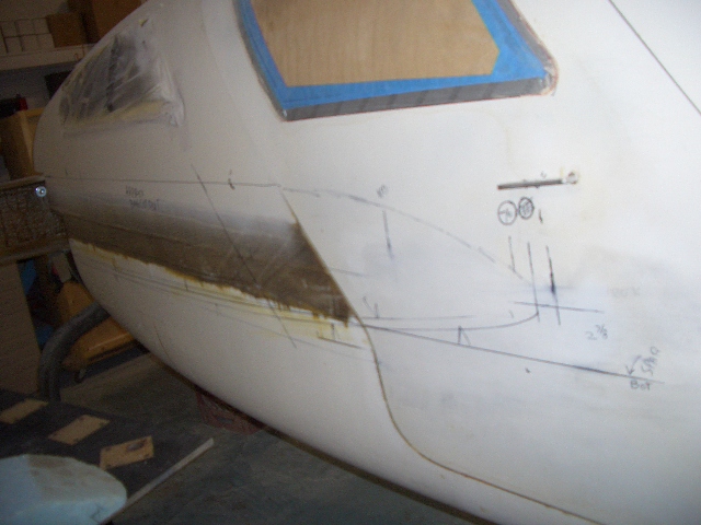
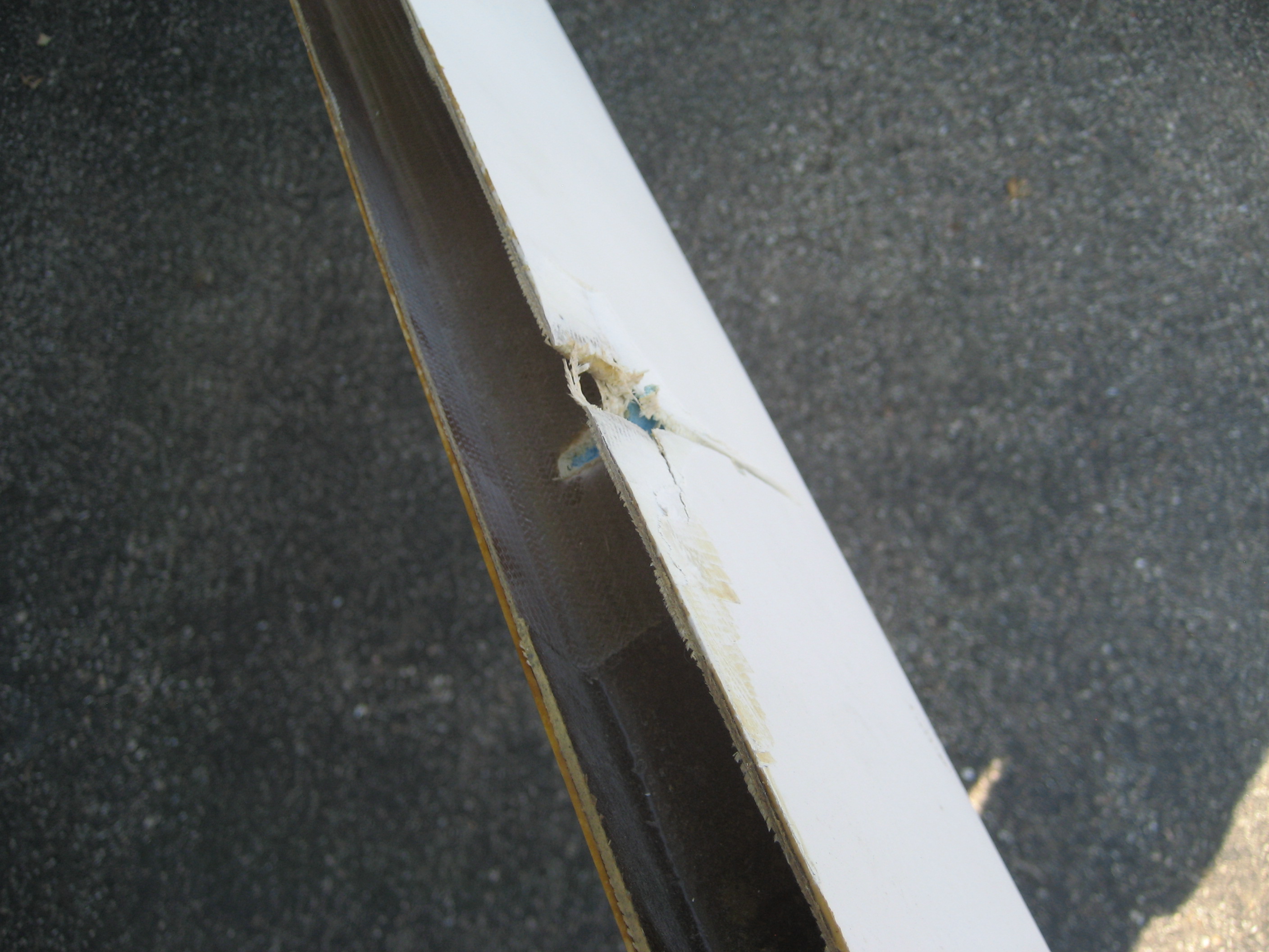
On airplanes with aluminum wings, they’re hollow and hold fuel. Velocity wings are a solid foam core and can’t be used to hold fuel. So an interface between the leading edge of the wing and the fuselage is created that will hold the fuel.

VelocityTopView6

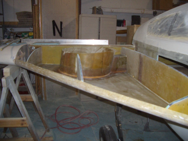
The shaded area are called “strakes” and will hold (hopefully) about 40-45 gallons of fuel on each side. But here’s the catch: To properly build the strakes, the wings need to be mounted. But I don’t have a big enough shop. With both wings on, the shop is about 12 feet too short.

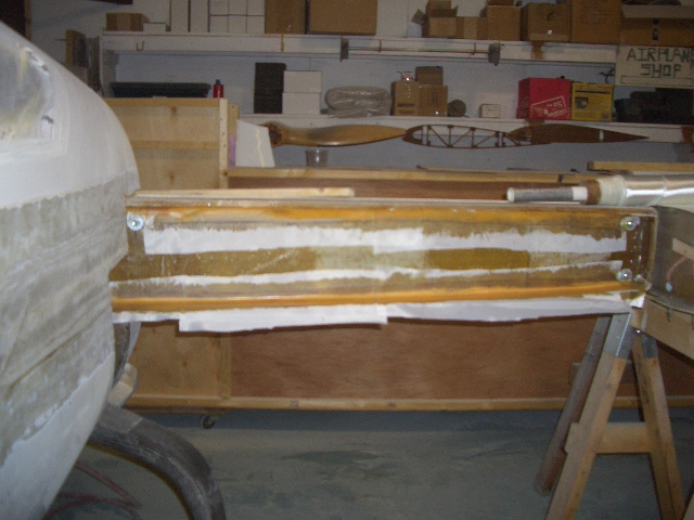
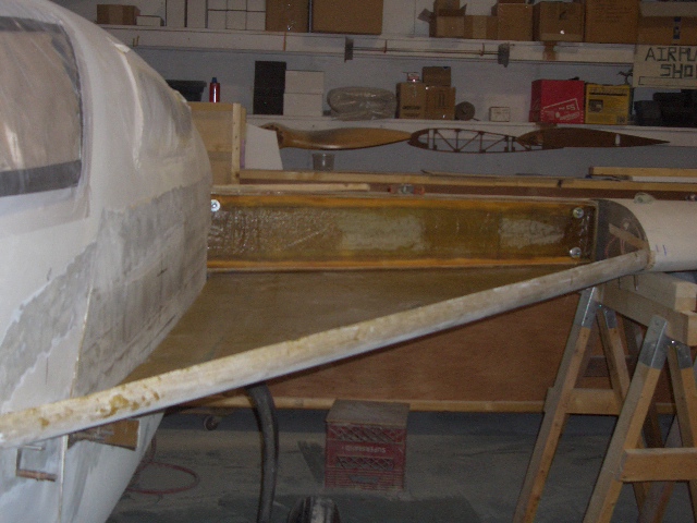
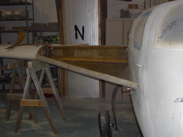
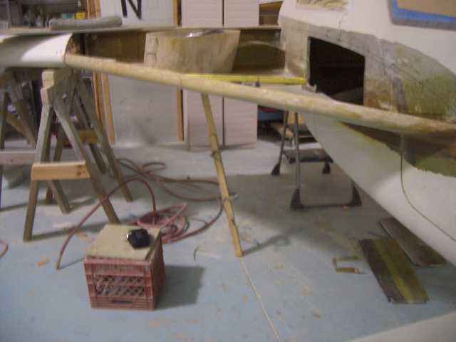
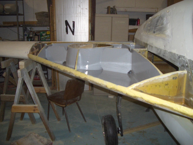
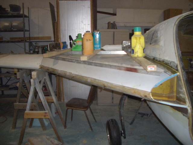
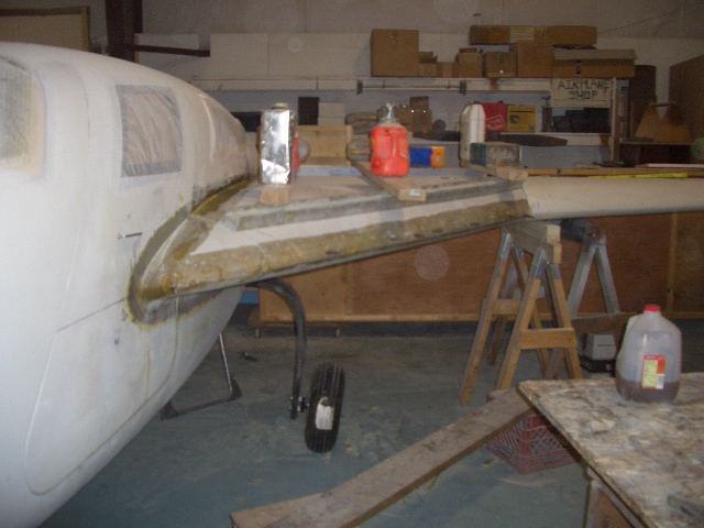
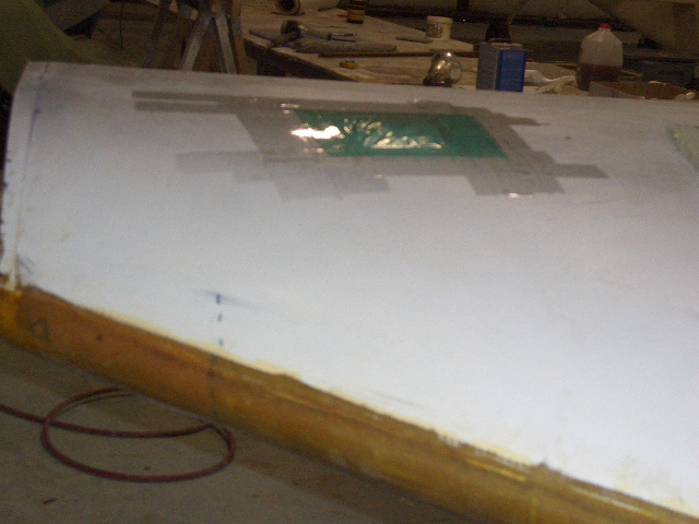
Here’s a picture with one wing on.
2008-12-17 image2008-12-17_15.50.04

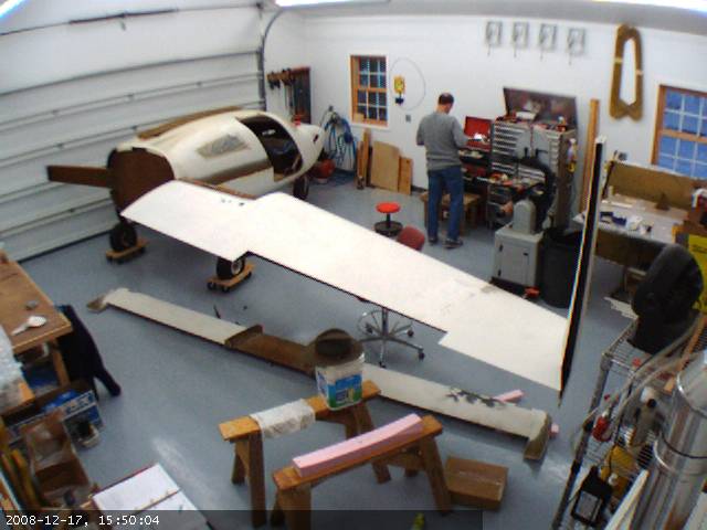
I could build the strakes one side at a time but that creates some problems.

  1. It takes twice as long.
  2. Even with one wing on, it’s a pain moving around to do the work.
  3. With one wing on, the center spar is unevenly torqued. It’s possible, with supports, to relieve this stress. But it’s a bit of work to get it just right. And if it’s not, the plane will not fly true without some adjustments.
  4. Building strakes is somewhat challenging. At least the first time. I looked at going down to the factory and helping out building strakes but they didn’t have any planes down there that were at that point of construction.

So I fussed about whether to build a temporary extension so that I could fit both wings on, do it one side at a time or send it out to a facility where I could do both sides.

Because this will determine how true the plane flies, I decided that caution rather than blindly fumbling in was the best course of action.

Malcolm at Hangar 18 was busy with two builds so he wasn’t available. I met Tom Wright at Oshkosh last year. Tom owns Advanced Composites Technologies. In addition to having build numerous Velocities, he’s also builds UAV’s. Malcolm said that Tom did good work so I made arrangements to ship the plane to Tom’s shop in Friedens, PA.  Then I’ll make the short flight out in the Cessna to work under the guidance of someone who has built a few strakes so that it’s done correctly.

Getting the plane on the trailer

2008-12-30 0009 DSC_0105 2008-12-30 0010 DSC_0106 2008-12-30 0029 DSC_0107

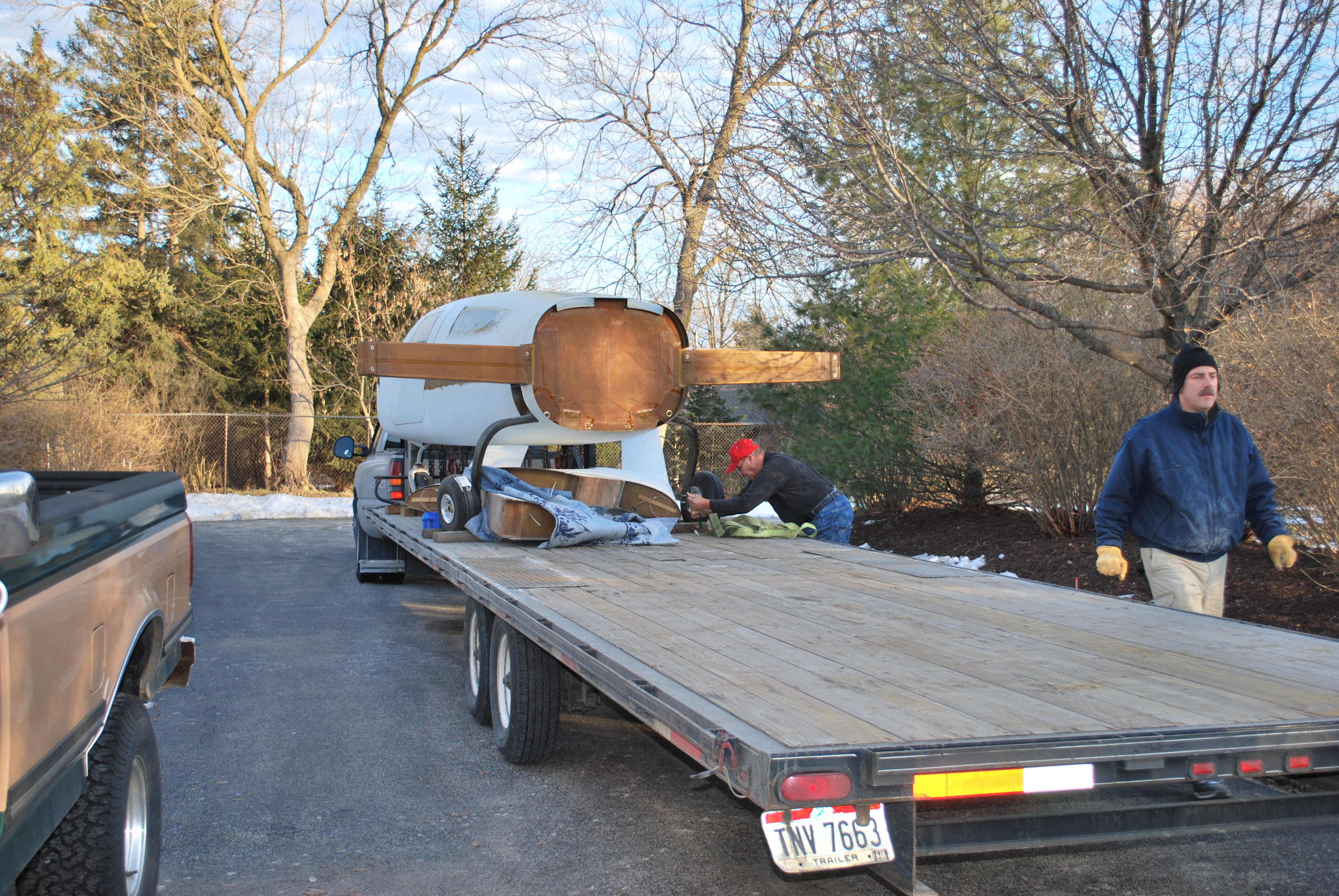
Loaded up with the wings underneath, strapped down and placarded.

2008-12-30 0154 DSC_0112

The battery on the truck was dead and I couldn’t get any of our cars in position to jump.  So I pulled the 1965 International Cub Cadet out.

2008-12-30 0029 DSC_0109  2008-12-30 0155 DSC_0113

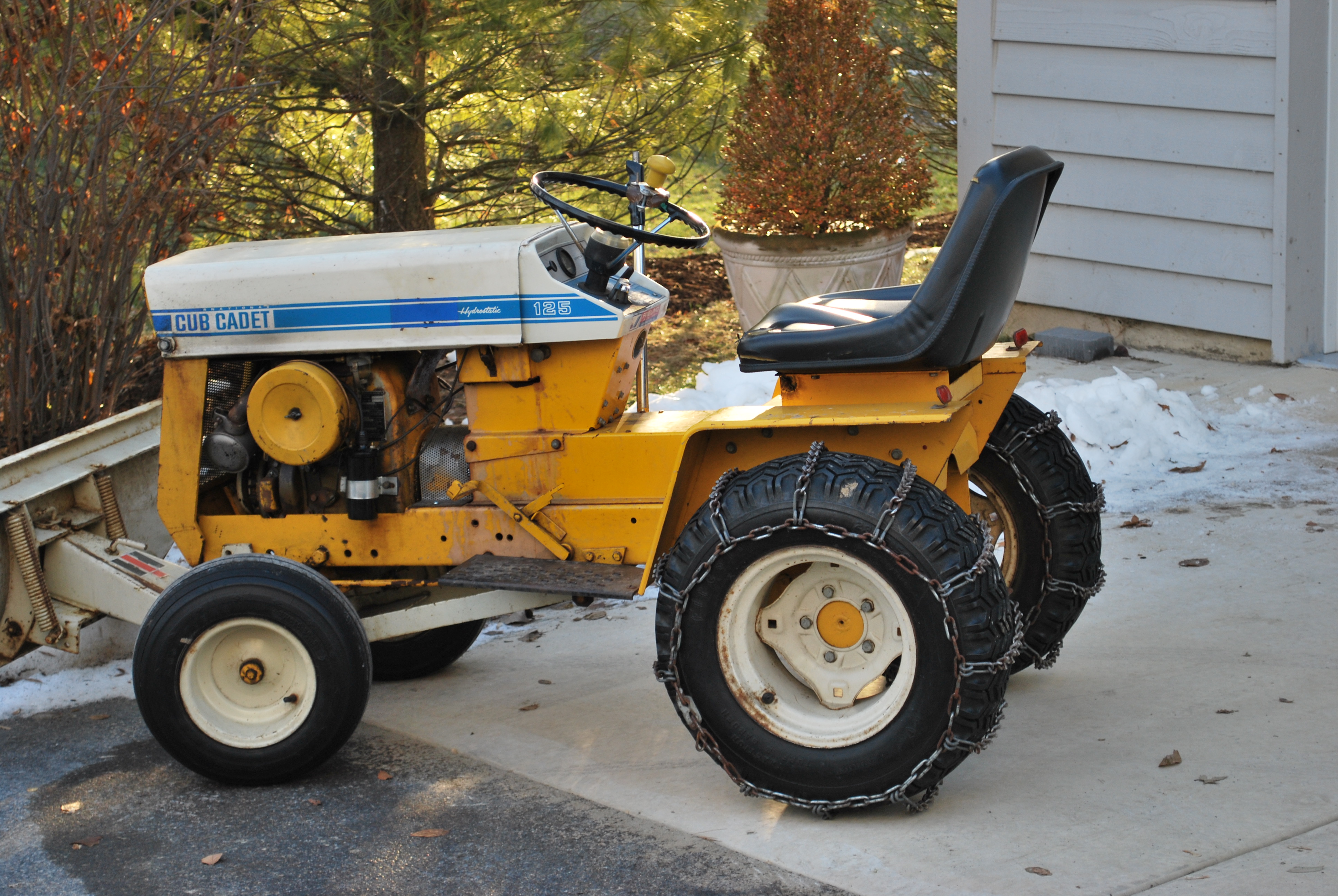
Worked like a charm.

9.2.3 Lower Strake Alignment

This entry is part 10 of 18 in the series 09 - Fuel System

Once at the shop in Friedens, PA the wings (both) were attached and the plane was raised up and leveled.

Left side

2009-01-14 0923 CIMG3886

Right side

2009-01-14 0924 ATC2 004

Then it’s time to determine how far forward the strakes will join to the fuselage. This is one of the factors that determine how much fuel you’ll be able to hold. The farther forward, the more fuel. A limiting factor is the door latching mechanism. This assumes that the door is opened up where the strakes are (which they will be). Some builders have modified the door latch they can put the strakes even farther forward. I decided to skip that modification. I am hoping for 44 gallons of fuel per side. That will give me about 1,000 mile range (5 hours). Which is much longer than I can usually sit in an airplane.

One of the critical factors is getting both side IDENTICALLY positioned.

Here are the markings on the pilot (left) side.

2009-01-14 0924 ATC2 003

And on the co-pilot (right) side.

2009-01-14 0924 ATC2 005

The lower strake skins are temporary put into position and the location at the center spar is marked.

The strake skins  are manufactured at the factory. They’re made of 1/4″ sheet of Divinycel foam with fiberglass cloth on the top and bottom. Where the strake skins attach to the center spar, the foam has to be removed and the foam is beveled and then covered with a layer of fiberglass.

Here’s a strake skin with the foam and inside layer of glass removed.

2009-01-14 0924 ATC2 002

The inside of the strakes had to be sanded, filled and recovered as they were not smooth enough.

Inside of one of the strakes after sanding.     

2009-01-19 1358 ATC2 006

This is the bottom left strake skin after sanding with a layer of BID and peelply. At the bottom of the picture you can see where the foam was removed.

2009-01-20 1456 ATC2 016

The top and bottom of the center spar (which is the structural component that the wings mount to) has to be prepared.

Left side of the center spar being prepped.

2009-01-20 1456 ATC2 017

Right side of the center spar finished and ready for the strake.

2009-01-21 1009 ATC2 019

The left side lower strake skin mounted in position.

2009-01-21 1037 ATC2 026

Right side lower strake skin.

2009-01-21 1037 ATC2 027

9.3.1 Fitting Wheel Well

This entry is part 11 of 18 in the series 09 - Fuel System

The bottom skin of the strakes are now permanently attached to the spar, fuselage and door.

The cutout for the landing gear has to be made. This allows the gear to raise into the strakes. Basically, the gear leg is raised until it hits the strake. Mark where it hits and trim away part of the strake. The gear will now raise a little further. Keep repeating until the tire hits. Then start cutting out larger pieces until the whole leg and wheel retract into the strake.

Looking under the right strake at the fuselage.

2009-02-03 1230 CIMG4000

Towards the left edge of the picture, you can see the opening on the side of the fuselage for the main gear leg. You can also (barely) see part of the bottom of the strake where an opening has been made for the gear leg.

Right side strake.

2009-02-03 1230 CIMG4002

Gear in the up position. The gear leg cover and wheel cover is positioned.

Two things to keep in mind here. One is that fixed gear Velocities can hold a bunch more fuel. And second, I am going to pick up a couple gallons per side with a neat trick. Notice how the wheel is at an angle when it’s fully retracted? Rather than seal that whole area off, I’m going to put an angled “cap” on it and use that space. Should yield about 1.5 to 2 gallons.

Making sure there’s sufficient space all around.

2009-02-03 1231 CIMG40032009-02-03 1231 CIMG40042009-02-03 1231 CIMG4006

Left side wheel well and gear leg well epoxied in place. Looking from the top (rear).

2009-02-03 1232 CIMG4009

Left side wheel well and gear leg well epoxied in place. Looking from the front.

2009-02-03 1232 CIMG4010

Right side (from front). Landing gear is held up with a piece of wood.

2009-02-03 1232 CIMG4011

Something else to point out here. Notice on the right side of the picture you can see a rectangular cutout in the side of the fuselage. This is an optional feature that almost every builder does. This is next to where the rear seat is located about elbow height. Basically the side of the fuselage will be moved out creating a space. This space can be used for open storage (no door), closed storage (door) or just a big ol’ armrest area. As an open area or open storage it makes a big difference how big the cabin “feels”.

How far you move this out depends on what you want. If you want a big area for storage, you move it out about 12″. But you lose fuel capacity. Don’t make the cutout and you pickup about 5 – 7 gallons. I decided to split the difference. Mine will be moved out about 5 1/2″. I’ll lose a little fuel but gain some space. I toyed with the idea of making it angle in at the top but decided that would just add work with not much gain.

The location of the wheel and gear leg well get transferred to the top strake skin. Also the fuel cap is installed.

2009-02-03 1233 CIMG4012

I’m doing two things different here. Number one: I’m not using the fuel cap from the factory. I looked at them but didn’t like the design and construction. I found a company that makes the fuel caps for race cars and bought a couple of those.

9.3.2 Baffles and Bulkheads

This entry is part 12 of 18 in the series 09 - Fuel System

As with traditional wings, the skins require an internal structure. In the strakes, this is accomplished with bulkheads that also serve as baffles to prevent fuel from rapidly moving inside the strake. The bulkheads are 1/4″ Dyvinicel foam with a layer of BID on each side. They are then cut to fit.

Glassing in the wheel wells and gear leg wells to the lower strake.

2009-02-10 0833 CIMG4016

Holding the wells down with a heavy beam while everything sets up. Also starting to install some of the ribs. These vertical pieces are to strengthen the area and to prevent the fuel from sloshing around.

Closeup of the inside-rear area.

2009-02-10 0834 CIMG4017

Right side from the front. After everything sets up.

2009-02-10 0834 CIMG4019

Additional ribs installed.

2009-02-16 1316 CIMG4020

Notice in the corners where the ribs/baffles meet that there are small cutouts. This allows the fuel to move. The cutouts are called “mouse holes”. 🙂

Tops of the wheel wells being prepared.

2009-02-16 1316 CIMG4021

Inside of the plane looking back at the right side. Fittings for the fuel supply, vent and return. On the left side of the picture you can see the storage area. The fuel line hardpoints are 1/8″ aluminum which are drilled and tapped to receive the fittings. They are then attached with epoxy and covered with 2x BID.

  2009-02-16 1317 CIMG4025

Right side, looking back from the front. The temporary trial fitting of the top skin.

2009-02-18 1454 CIMG4029

9.4.2 Fitting Upper Strake

This entry is part 13 of 18 in the series 09 - Fuel System

Because there’s no way to see inside the strakes with the upper skin on, the height of the ribs/baffles is an approximation. To get a perfect fit, duct tape (is there anything it won’t do?) is applied to the inside of the upper skin where it will contact the ribs. A bead of epoxy/Cabosil is run on the tops of all the ribs. The upper skin is then lowered in to position and left overnight. The next morning, the upper skin is carefully removed.

This is the result

2009-02-23 1032 ATC 0012009-02-23 1032 ATC 002

2009-02-23 1032 ATC 0042009-02-23 1032 ATC 003

After a little clean up of the spots where oozed too much, it’s time for Jeffco. As you may remember from the sump tank, Jeffco is tricky stuff! First off, it’s not needed with the type of fuel that is presently used for piston engine airplanes (100 octane, Low Lead). But if the fuel is ever changed, it could react or eat through the epoxy. So just about all builders coat their tanks with Jeffco. A very hard, resistant epoxy. The problem is the stuff has a tendency to exotherm (heat up) rapidly. When it does, the mixture will set. So it has to be mixed in small batches and applied. Oh yeah, and you have to keep a wet edge. If the area that you’re working next to sets up, you have to let it harden and then sand it. So this is definitely a good multi-person job.

Shiny fuel tanks!

2009-02-26 0918 ATC 009 2009-02-26 0918 ATC 007 2009-02-26 0918 ATC 008

The last picture shows the wheel well. Remember how I said that I was going to use the the angled area for additional fuel? That area needs a bit more work. Openings so the fuel can flow in and out have to be cut and then the Jeffco can be applied.

Wheel well jeffco’d:

2009-03-02 0924 ATC 0162009-03-02 0924 ATC 015

Here’s the outside edge of the left strake looking back from the front. On the right, you can see two of the bolts that hold the wing in place. The hole in the bottom provides access to the bolts so the wing can be removed.

2009-03-02 0925 ATC 018

9.4.3 Upper Strake Installation

This entry is part 14 of 18 in the series 09 - Fuel System

Inside of the plane looking at the right side. The rectangular opening is the area that extends into the strake. The plans say make it 11 inches deep but mine is only about 5 inches.

2009-03-02 0925 ATC 020

 Another modification. As you have seen, when the landing gear is retracted, the wheel is at an angle. To allow it to retract further, a “divot” is cut into the inside of the top skin of the strake. Then it is covered with two layers of BID.

It’s kind of hard to see it in this picture, but the lighter colored area is the divot.

2009-02-26 0918 ATC 012

The inside of the top skins coated with Jeffco . You can see the area of the wheel well that won’t be holding any fuel and the divot is a little easier to see.

2009-02-26 1446 ATC 013

The inside of the top skin has to be sanded where it will adhere to the bottom strake and ribs.

Here’s the inside of the top skin after sanding.

2009-03-02 0926 ATC 026

Finally it’s time to bond the top strake skin on. An epoxy/cabosil mix is applied to the top of the outside edge and ribs.

Strakes ready for the top.

2009-03-02 1325 ATC 0322009-03-02 1325 ATC 030

2009-03-02 1325 ATC 0292009-03-02 1325 ATC 031

Once the top is on, everything is weighted down to hold it in place.

2009-03-02 1433 ATC 0352009-03-02 1434 ATC 038

After everything has cured, it’s time to test for leaks. Since how well the fuel caps seal is an unknown, they’re covered with plastic and taped.

2009-03-09 0952 ATC 0532009-03-09 0930 ATC 048

Many builders attach a pressure gauge to one of the fittings and then pump some air in the tank and monitor the pressure overnight. Tom has a slightly different approach.

He uses an altimeter which is connected to a fuel fitting. The a vacuum pump is used to create negative pressure in the tank until the altimeter reads 1,000 feet. Then everything is left overnight. If there are no leaks, the next morning the altimeter will still read 1,000 feet. If it reads zero, then there’s a leak.

Fuel tank test underway.

 2009-03-09 0952 ATC 0522009-03-09 0931 ATC 051

Everything is done and now the airplane comes home!

A word or two on the idea of getting outside help.  As I mentioned before, the strakes become a structural part of the airframe.  It’s what keeps the center spar from twisting.  As such, doing it right is absolutely critical. In addition, to that, even after doing everything just right, there can be leaks.  There are “tricks” that are used to find and fix these leaks.  And finally, manpower.  I am building 100% solo.  I have zero help. As a result, I have had to come up with some inventive solutions building so far. But with strakes, there are a couple of situations where quite literally, the more people the better.  I just don’t have access to that resource. So those are just three of the things that resulted in me getting some outside help.

At the end of all this, it took a little less than 3 months start-to-finish.  It would have been less had I been able to get to PA more often. At the end of the process, I’m very happy with the results.  But even with the very experienced help of Tom Wright, there are a few things that if I had to do it again, I would have done differently. For example, I would have 1) Slanted the baggage opening of the strake cutout in at the top. This would have resulted in more fuel capacity without a loss of much usable space. 2) Really lowered the gear leg tunnel to maximize the fuel capacity. 3) Made the fuel caps flush and moved them inboard a bit. And there probably more. I can’t imagine how long this would have taken had I tried to do it solo.

Thanks for the help Tom!

00 Airplane returns

This entry is part 24 of 28 in the series 00 - Prep/Logistics

The airplane arrives back from Tom’s shop today.

Backing down the long driveway.

2009-03-16 1338 IMG_84802009-03-16 1338 IMG_84812009-03-16 1340 IMG_8482

Unfortunately, there was some shipping related damage (I wasn’t there when it was loaded up). Either the wing shifted forward or the fuselage shifted back (that’s what I’m betting on) and the upper fuselage skin dug through the winglet.

2009-03-16 1400 IMG_84862009-03-16 1359 IMG_84842009-03-16 1400 IMG_8485

The good news is that it was relatively minor and since it’s a composite, the repair isn’t that difficult and there will be no loss of structural integrity.

Here’s an animated GIF from the shop cam that shows before and after.

before-after

4.2.9 Landing Lights

This entry is part 5 of 5 in the series 04 - Bulkheads

I primed the canard with Akzo-Nobel 2K gray primer. This is the first part of the primer that Malcolm uses.  Once the primer was dry, I had to locate where the ballast would go. because the wire harness which connects the lights to the ballast is only six feet long, I put the ballast as far outboard as possible.

2009-04-05 1331 IMG_8518

Because the mounting tabs are not flush on the bottom, I would need standoffs. I decided to use wood.  And since I hate using sheet metal screws, I decided to embed nutplates in the wood.

2009-04-05 1333 IMG_85202009-04-05 1333 IMG_8521

Here is the landing light ballast mounting hardpoints for the left light glassed in position  2009-04-08 1704 IMG_8541 2009-04-08 1705 IMG_8543

Once that was done, I (of course) had to connect everything and turn some lights on.

2009-04-03 1153 IMG_8509

These things are BRIGHT!  But that’s when I discovered the the lens was melting. That light gets REAL hot. So one of my custom made lenses was toast. I called Xevision and talked to one of their engineers and explained what was happening and asked if there was some special material that I should be using. He asked where I was testing the lights and told him that I was doing this in my shop.  In true Adam Savage fashion, he said “There’s your problem”.  He said that outside when the airplane is moving, the air over the lens will keep it cool enough. That seemed unlikely to me so I did a test.  I positioned a small fan about four feet from the other landing light on the slowest setting.  Then I turned on the landing light and with my non-contact thermometer, I monitored the temps. I was seeing 180F on the lens and 110F on the canard. Actually cool enough that the lens didn’t get soft. But not as cool as I would like.

Malcolm suggested a type of ventilation system.

So I drilled a hole from the back of the canard to the cavity for the landing light.  I bonded some nylon tubing in and trimmed it flush with the surface of the canard.  This will create a slight vacuum pulling air from the doghouse through the landing light area… hopefully.

2009-04-12 0847 IMG_8576  2009-04-12 0847 IMG_85742009-04-26 1201 IMG_8578

Not sure if it’s needed or will even help. We’ll see.

7.6.2 Main Gear Sockets

This entry is part 29 of 39 in the series 07 - Landing Gear

The upper part of the gear legs (which are inside the fuselage) are supported fore and aft by sockets that they are held captive when the gear is extended. These sockets are made to be perfect fit to the upper gear leg by wrapping the area with duct tape and then applying 3 layers of triax.

Duct tape on the upper gear leg.

2009-04-08 1305 IMG_8530

Three layer of triax.

2009-04-08 1347 IMG_8532

Once cured, they are removed and then trimmed to the rough dimensions.

Currently, the only permanent aspects of the main landing gear are the pivot points which the gear legs pivot at and the over-center linkage which defines the distance between the tops of the two gear legs. So right now the over-center link can move left to right (which in turn lowers one leg while raising the other) about 1 inch. Once the sockets are in there will be no movement at all. So getting that position exact is critical.

This is the left upper gear leg and socket where it intersects the slant bulkhead. I’ve already created a notch in the bulkhead to accept the gear leg and socket.

2009-04-09 1555 IMG_85452009-04-09 1555 IMG_8544

Now the task is getting the two legs perfectly level. So here’s how I did it.

I raised and leveled the airplane, removed the axles from each leg. Then I leveled my laser level and shot the beam through the lower/rear hole in the gear leg.

Laser is level.

2009-04-11 1233 IMG_8552

Shooting from the outside at the right gear leg right through the center of the hole.

2009-04-11 1234 IMG_8554

And it’s a little low on the left side.

2009-04-11 1234 IMG_8555

Moving the gear legs a slight amount (lowering the right leg raises the left) and the beam is centered on both holes. Once I determined the method worked, I raised the gear and prepped the transverse and slant bulkheads for bonding in the sockets.

2009-04-12 0817 IMG_8569

Then the gear sockets are fitted on the gear legs and lowered gear with a penny is inserted into the over-center link. This keeps the upper arms spread slightly beyond where they are when the gear is down. This will prevent the gear from binding in the sockets when it’s lowered.

2009-04-11 1238 IMG_8563

Next I determined the correct position of the gear legs using the laser level and secured the position. Then I used structural adhesive/cabo to bond the sockets to the bulkheads. Once the adhesive has cured, the sockets to bulkhead is reinforced with a radius and BID on all sides.

2009-05-27 1647 IMG_8641a        2009-05-26 1058 IMG_8633

I will do the layups on the bottom when I flip the plane over.


10.1.2 Elevator Trim

This entry is part 10 of 11 in the series 10 - Control Sytem

I don’t mean to go off on a rant here…

One of my jobs when I’m not training (the thing that pays for the airplane) is writing training manuals. So I’m a bit more critical of instructional material than your average person and I’m constantly finding areas of this manual that need improvement.

 After talking with other builders, this seems to apply to a lot of homebuilt aircraft, not just Velocity’s.

On to the task at hand… From the sequenced flow chart, I need to install the “Pitch Trim Actuator”. Up and down movement of the airplane in flight is done with the elevators.  Pull the stick back and the nose goes up. Push the stick forward and the nose goes down. In cruise flight, you don’t want to have to be pushing forward or pulling back just to stay level. So a small electric motor moves a spring to a position that will apply the necessary force so that you don’t have to push or pull the stick to maintain a particular attitude.

This task has to do with mounting this electric motor.

Here’s a page from the manual:

2009-05-09 1450 IMG_8602

This is looking from the left side. The canard is on the bottom. The large black object is the actuator. On the left is where it mounts to the canard by means of the “Long Bracket” (Part Number VAB-02). The bracket will be connected to the “Aluminum Hardpoint” which will sit on the “Shim”. Seems pretty straightforward.

Here’s the text:         

2009-05-09 1451 IMG_8603

Hmmm. The first sentence is in bold. Must be important, huh? “Located a position for the trim spring that will not interfere with the radios.”?!?!?!

What radios? Installation of the radios is a LONG way away. Heck, I don’t even HAVE the radios. Nor have I even decided what radios or where they’ll be installed. So how do I figure out where to put this thing? I looked at the websites from other builders and looked at their pictures. Hopefully, my location will be fine.

This is the area of the canard where I’ll mount the actuator.

2009-04-26 1219 IMG_8581

The piece of blue foam cut and formed to the correct shape is the “shim”.

2009-04-26 1219 IMG_8582

A piece of aluminum cut to size on top.

2009-04-26 1220 IMG_8583

Everything covered with two layers of BID.

2009-05-09 1452 IMG_8604

The actuator.

2009-05-09 1452 IMG_8605

The “Long Bracket”.

2009-05-09 1452 IMG_8606

Wait a minute… The actuator looks like the picture of the actuator, but the bracket doesn’t look like the bracket. Back to the manual where we see the text “Modify the long bracket (VAB-01) as shown in Figure 10-2 to allow the actuator to move up and down.”

Well this is getting interesting. I’ve got to cut this piece “as shown” in the picture. No dimensions, no template, just make it look like a picture in a Hanna/Barbera cartoon. Okay, that shouldn’t be too difficult, just cut it so the end of the motor will fit.

But wait a minute… In figure 10-2 the “Long Bracket” is part number “VAB-02” but in the text they say “Modify the long bracket (VAB-01)”!

Now what?

So I reread the entire section repeatedly trying to determine exactly what I’m supposed to be cutting. In the end, I come to the conclusion that the text is wrong and the figure is right.

Long Bracket (VAB-02) after modification.

2009-05-09 1611 IMG_8608

Hardpoint drilled, tapped with Long Bracket (VAB-02) and trim actuator mounted.

2009-05-09 1635 IMG_8612

If I had to do this task again, I could probably do it in an hour. But with the research on the location, the part number discrepancy and trial and fit for the modification of the bracket, I probably spent the better part of 6 hours on this.

At this rate, I’ll be done in ten years. 🙁