7.3 Nose Gear Door Mechanism

This entry is part 35 of 39 in the series 07 - Landing Gear

One of the final tasks for the nose gear door mechanism is a spring at the actuator. The gear is retracted with a hydraulic cylinder. But when retracted, it can (and does) move in flight. With a hard link between the nose gear leg and the actuator, the door will constantly be opening slightly when the nose gear bounces.

The fix is to put in a heavy spring between the nose gear leg and the actuator.

So I got a large spring and mounted it to the actuator.

2010-06-07 1508 IMG_05992010-06-07 1508 IMG_06002010-06-07 1508 IMG_0601

Installed.

2010-06-19 1421 IMG_0611 2010-06-19 1421 IMG_0613 (Medium)

 Now when the nose gear moves a bit, the doors will stay closed. A final task is to create an up-stop behind the actuator that will define the closed position of the gear doors.

00 Moving to Hangar 18

This entry is part 26 of 28 in the series 00 - Prep/Logistics

Big changes!

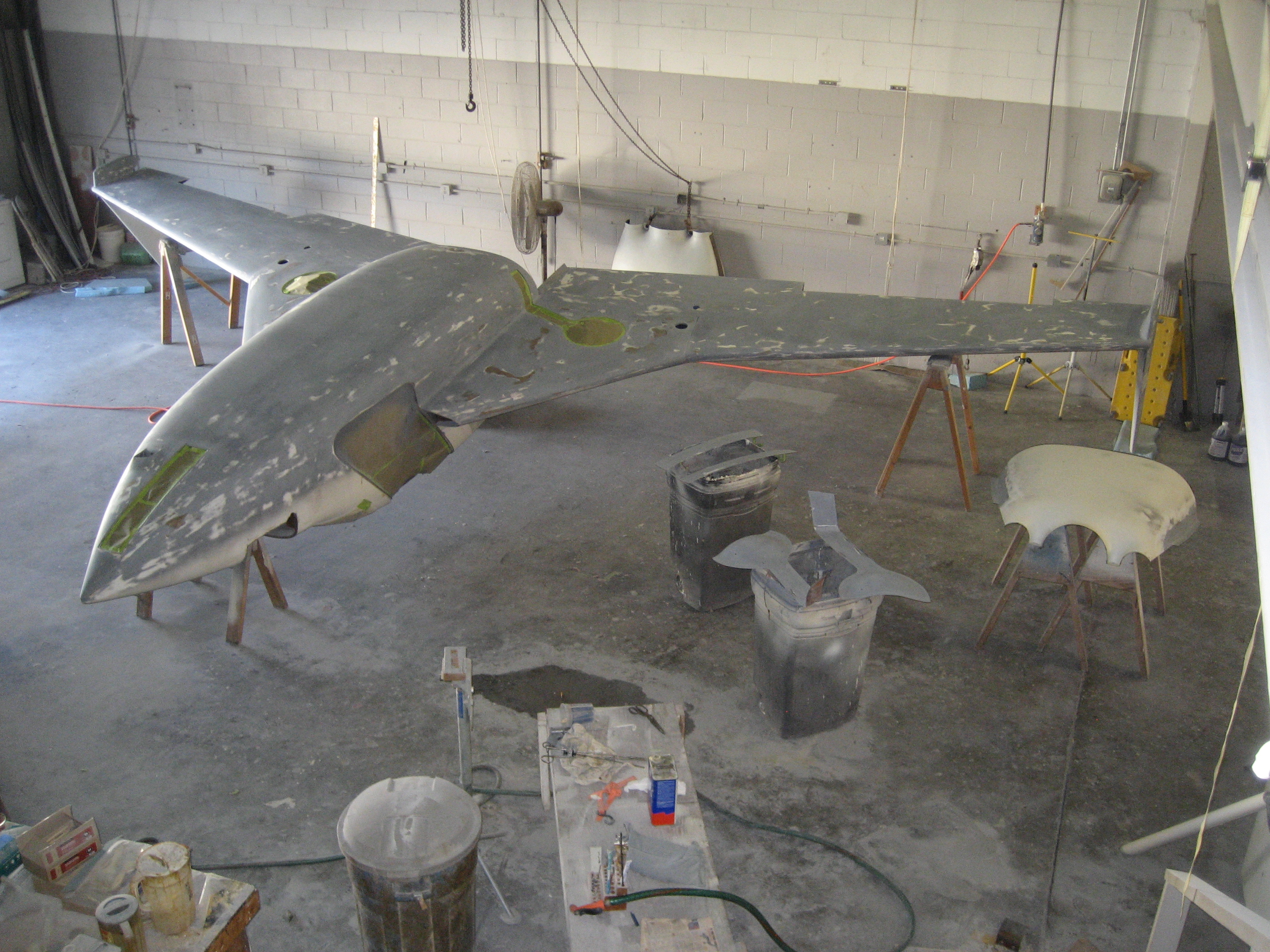
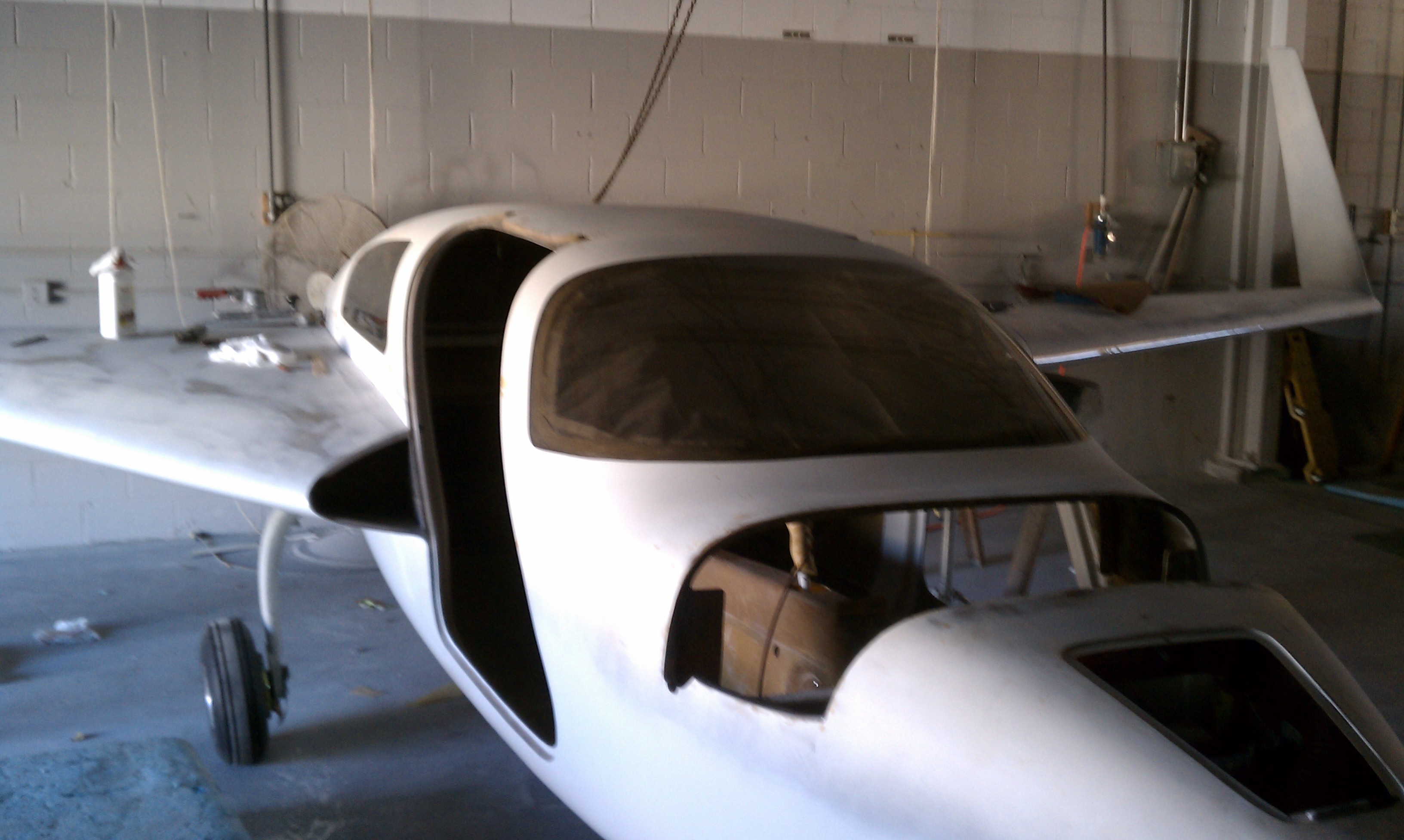
So things have been moving along. I got a bit stalled when the plane got upside-down. The landing gear went okay, but I was having a hard time getting started on putting the wings on and finishing the bottom. I just couldn’t figure out how to get a wing on and without a crew of people to help. But I was getting there. I built a jig to hold the plane at the correct position and was getting ready to attach a wing.

And that’s when my lovely wife told me she was being relocated back to the Atlanta area. Now I was okay with that. The only reason we were up here was her job and it will be nice not having to plow the driveway a couple times per year and get sweet tea, BBQ and grits.

 But then it occurred to me that I had a purpose-built workshop and that we may not find a house in Atlanta that had a workshop to hold the plane. So we made a scouting trip down and I discovered two things:

  1. The chances to finding a home with a suitable workshop were almost non-existent.
  2. The population of metro Atlanta has exploded in the 11 years we’ve been gone. It’s just plain DENSE with people.

And add to that, Ann got an offer that would allow here to work from home most days and she could live anywhere.

So the bottom line is; We’re moving… Again.

Which means that I went into warp drive trying to figure out what to do with the Velocity.

I could rent commercial space or get a hangar to build in. Either of those options would cost something per month but my biggest issue is that I would no longer be able to walk into my shop and spend 30 minutes on something. I would have to drive somewhere which would be at least a 30 minute round trip commute. I would also have to move all of my tools there so when I needed to do something around the house, I’d have to drive 30 minutes to get a wrench! Plus, no internet access (you’d be surprised how much time I spent in my shop looking something up on the internet while building).

So renting space looked like a no-go.

Which brings me to Hangar 18. Malcolm Collier (who I’ve mentioned before) is a professional builder who has built numerous Velocities (He’s been my “go to” guy when I have a question). That’s his business. People buy the kit, ship it to Hanger 18 and spend time there working with Malcolm building their Velocity.

But the economy has been hitting everyone. Malcolm finished his last project almost a year ago and his new builds kept getting pushed back by their builders while they wait out the economy. So he made the decision to shut down Hangar 18 and go to work with a startup company developing a new airplane. Which kept getting pushed back. So I asked if he was interested in “one last build”. And he agreed.

I’m really excited about this for a couple of reasons.

  1. I’m going to have one of (actually THE) best in the business looking at everything that I’ve done. If there’s anything that isn’t right, it’ll be made right.
  2.  No more scratching my head for 2 hours trying to interpret the manual or figuring out how to do something. Now it’s “Hey Malcolm. How does this go together?”
  3.  Labor. There will always be at least 2 people around so when something needs to be moved, lifted, etc…
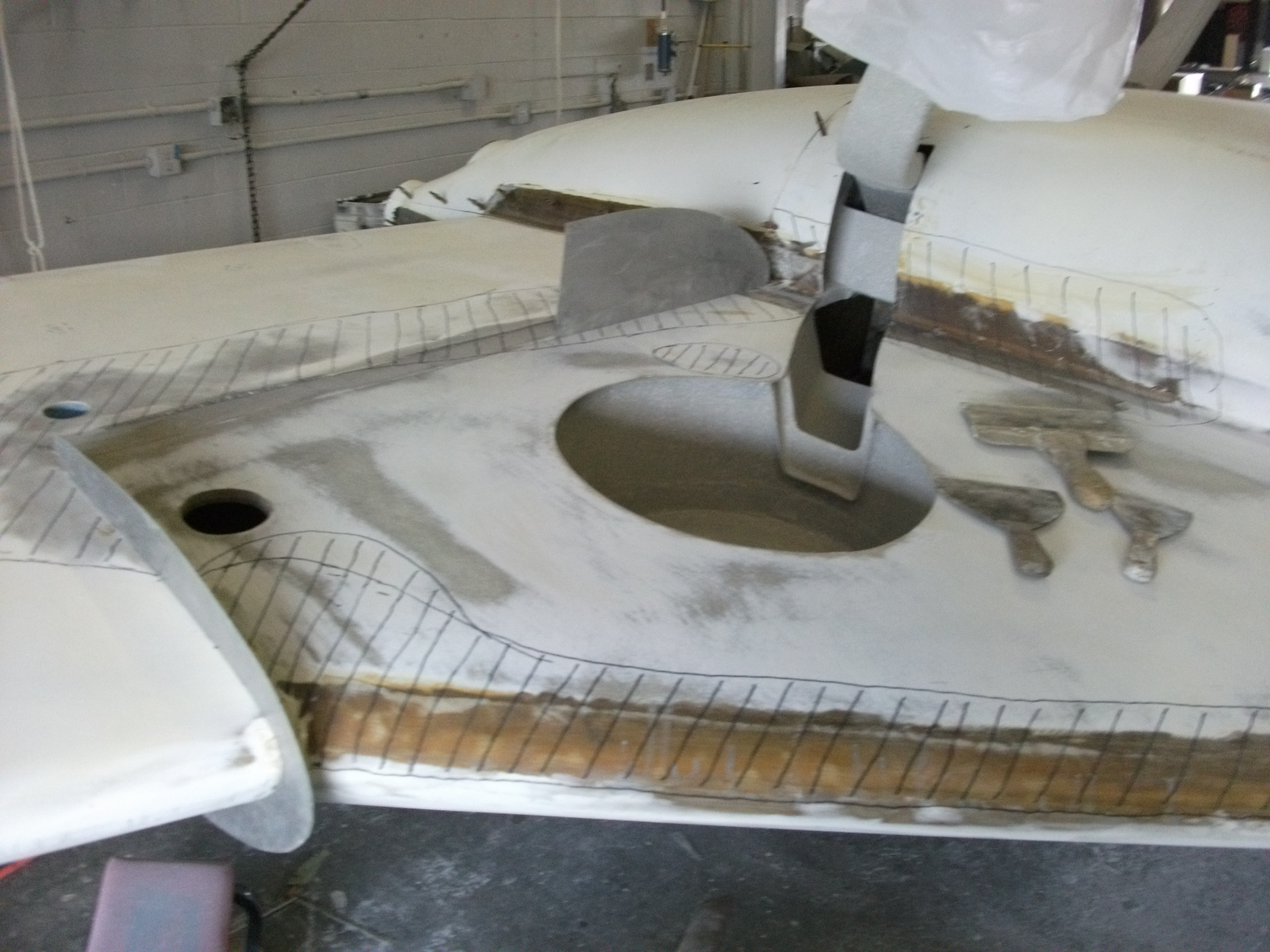
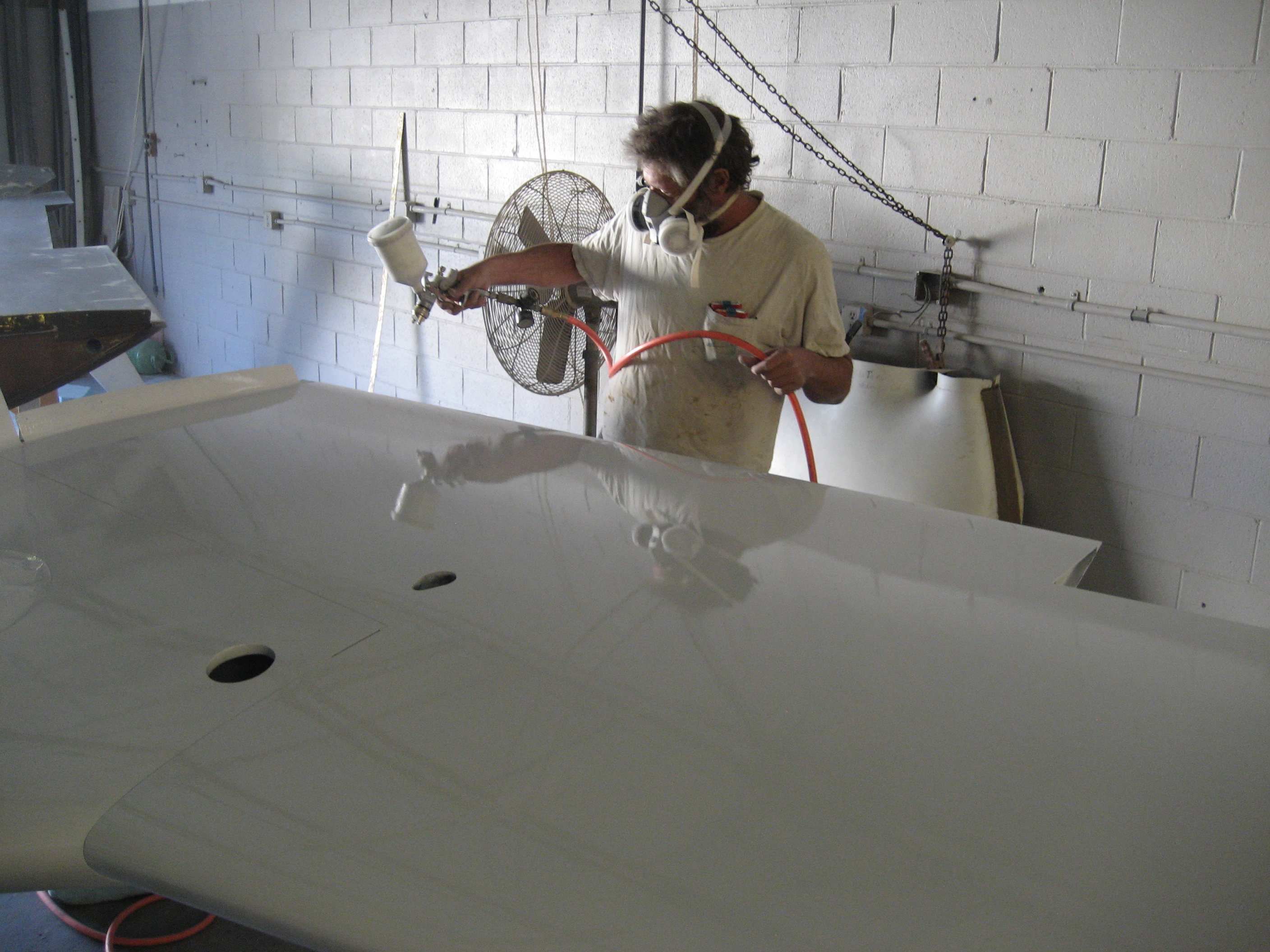
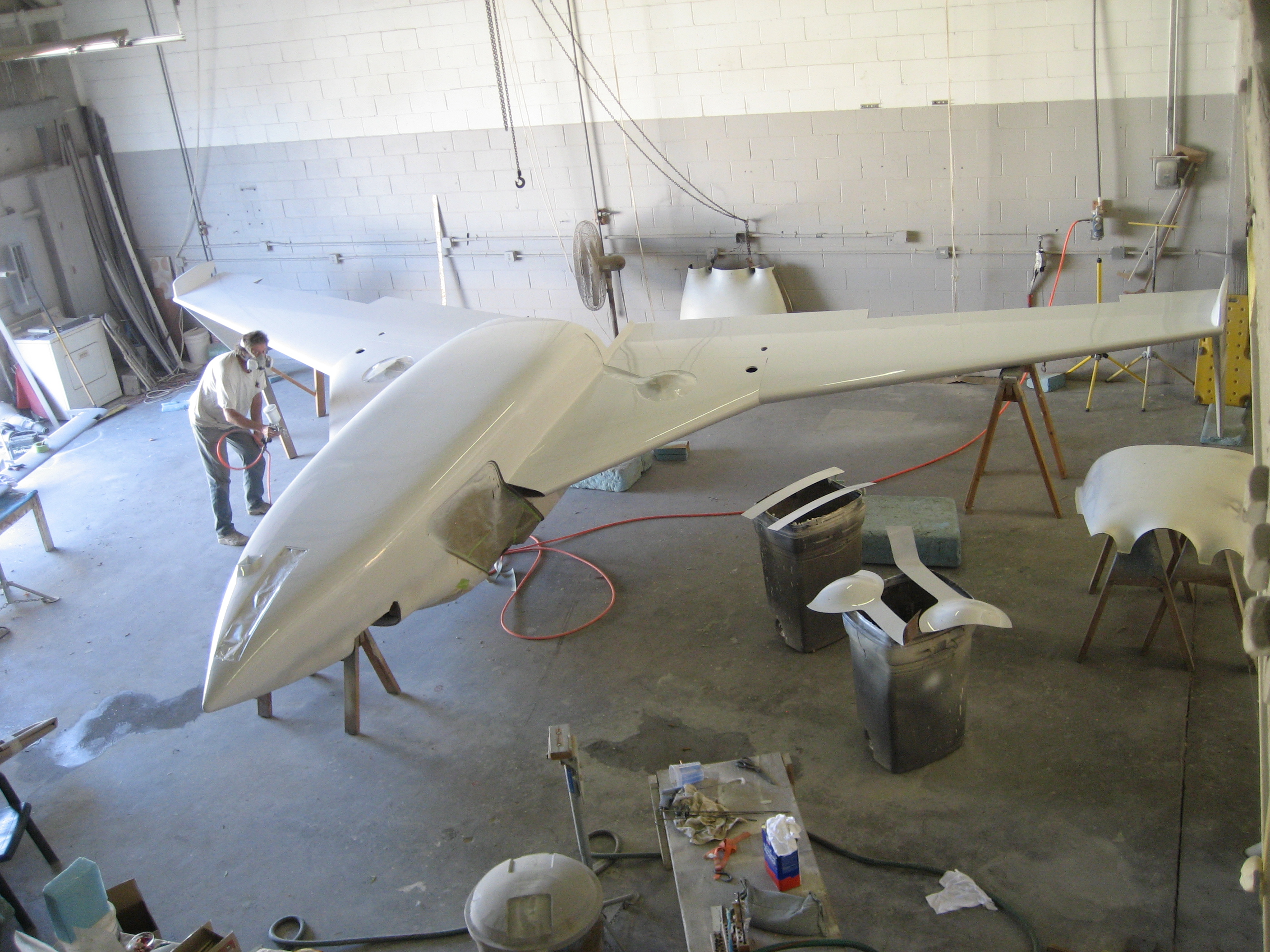
  4.  Labor (again). Nothing is as tedious as filling, sanding, filling, sanding, filling, sanding. With Me, Malcolm and his worker, it’ll go much faster.

Of course, the downside is I’ll have to spend a couple weeks a month in Greenville, SC. And I’m now going to have to pay for Malcolm’s time and his worker.

But then again, I’ll probably be in the air sooner.

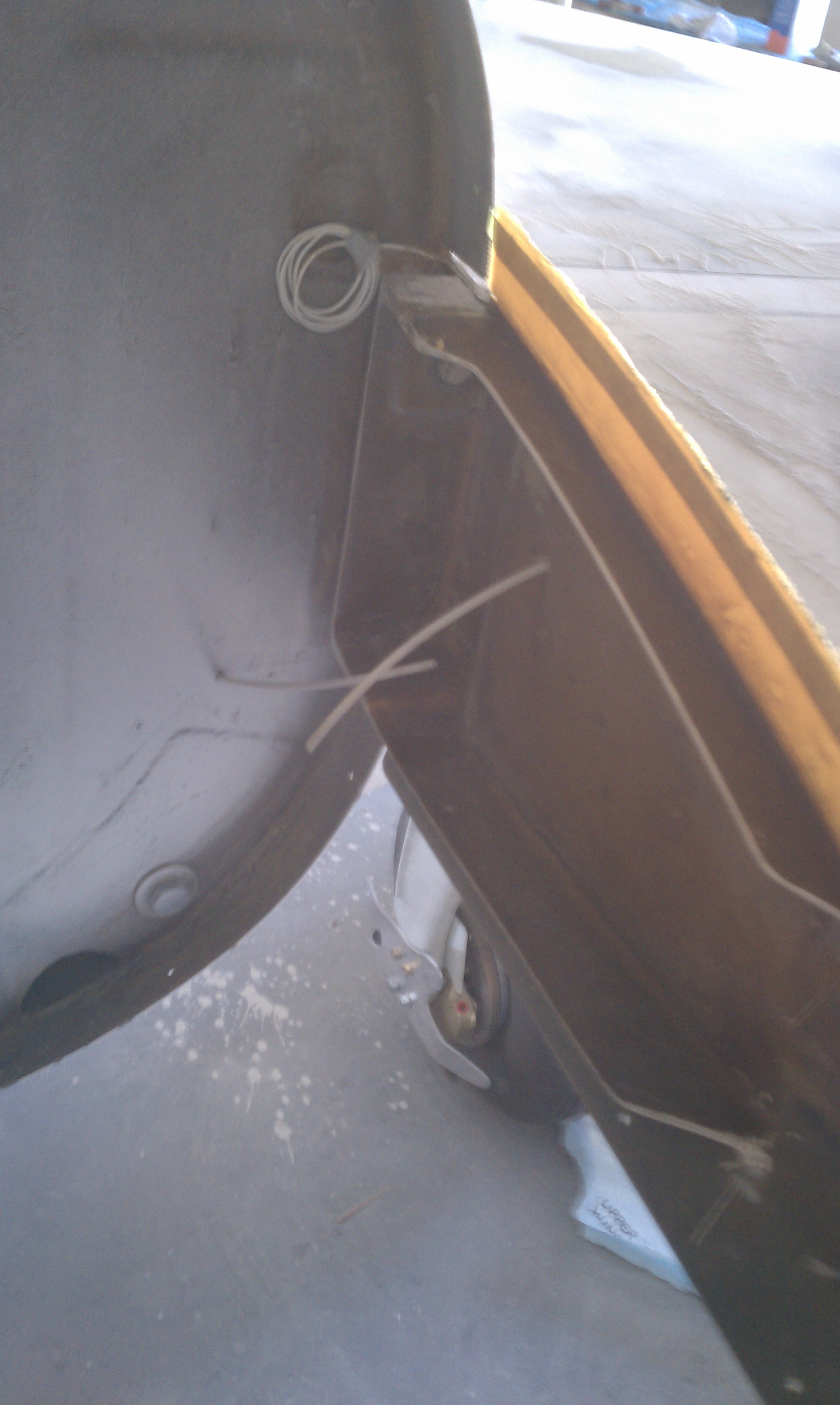
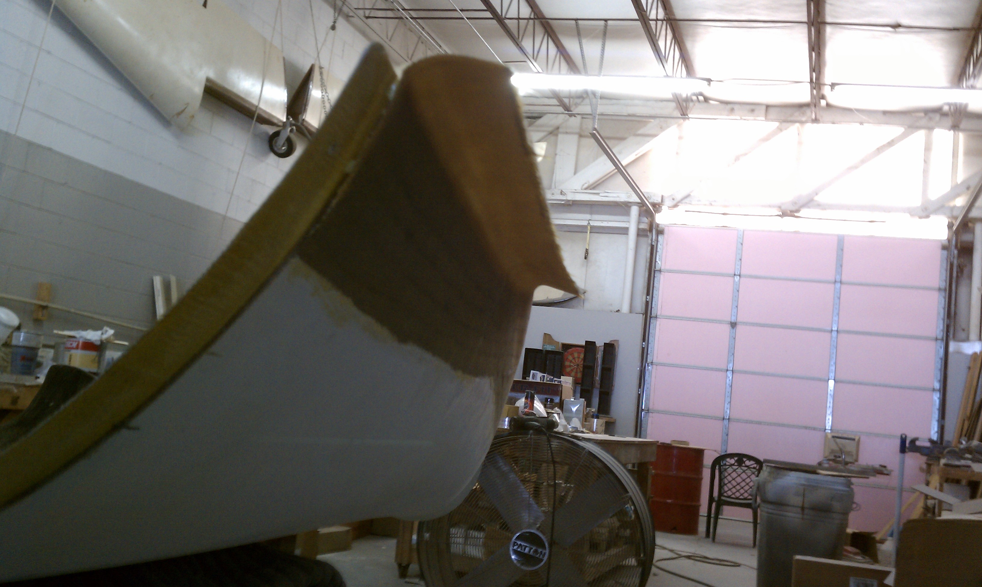
So I’ve spent the last month getting ready for the move. Disassembling some things, packing, organizing, etc.

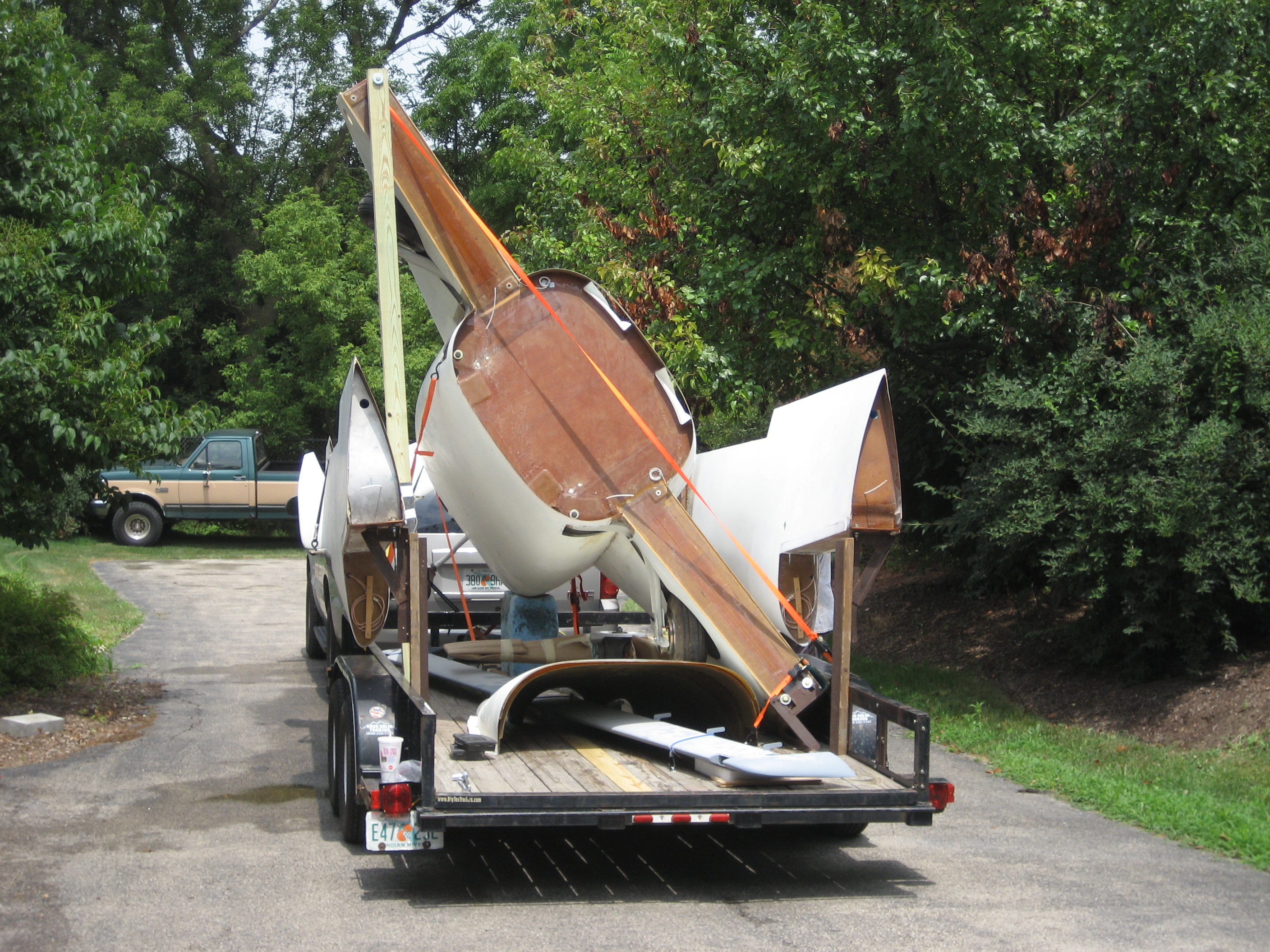
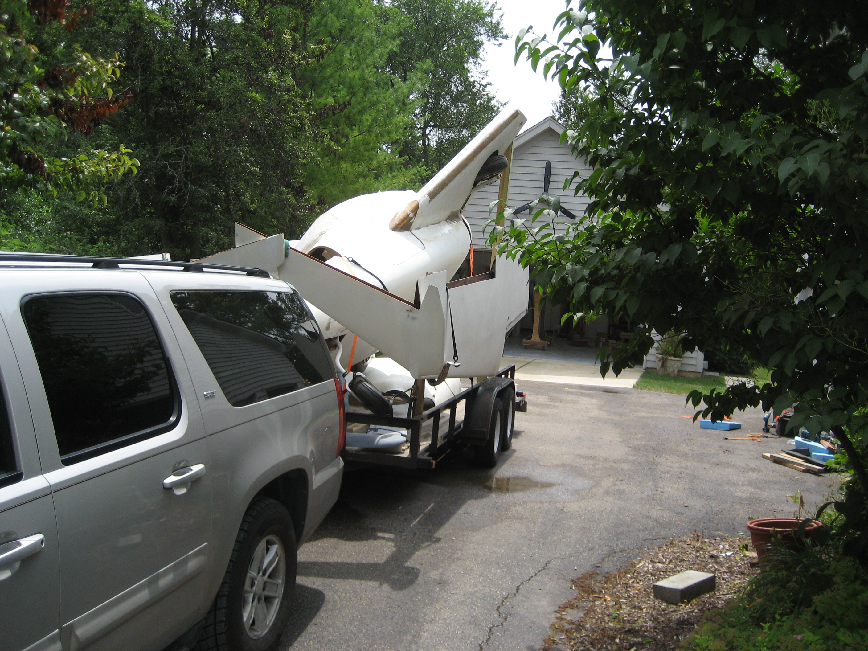
On July 22nd, Dan Fast (same guy who brought it up 2 1/2 years ago arrived to take it down to SC.

On the trailer and ready to go.

2010-07-22 1149 IMG_0670 2010-07-22 1149 IMG_0672 2010-07-22 1150 IMG_0673

I got a call from Malcolm on the 23rd that the plane arrived and had been offloaded.

2010-08-05 1413 MC 0082010-08-05 1410 MC 001

2010-08-05 1412 MC 0062010-08-05 1411 MC 004

Now I’m looking for a room in Greenville where I’ll spend a couple weeks per month. For now there’s a bunch of filling and sanding and I’ve got to do “real” work for a good part of August so I probably won’t get down there until September.

11.1.4 Lower Cowling to Wing Flanges

This entry is part 36 of 39 in the series 07 - Landing Gear

Malcolm has a chain hoist so we don’t need a bunch of people to flip the plane. It also makes for some very interesting photo op’s. 

Ready for lift-off
2010-08-09 0835 MC 0112010-08-09 0831 MC 0102010-08-09 0831 MC 009

Coming back down.
2010-08-09 0923 MC 012

Back to upside down.
2010-08-09 1103 MC 014

Something I never got to. Upside down with both wings on.
2010-08-09 1503 MC 016

Malcolm says now is a good time to start fitting the engine cowling. If I had to guess, it would have taken me weeks to do this. But when you’ve done it dozens of times, it’s easy AND fast… With one minor exception. For some reason, My upper cowling didn’t have a flange. The flange is a lip that is created when the cowling is made. This flange is used during the initial mounting to hold the upper and lower cowls together. So we had to make some temporary flanges.

Lower cowl in place.
2010-08-10 1225 MC 024A

Here you can see where the cowl is cut for the trailing edge of the wing.
2010-08-10 1225 MC 024B

Lower cowl cleco’d to the fuselage.

2010-08-10 1334 MC 024C

Upper cowl mounted. You can see the “temporary” flange on the upper cowl (small white tabs where the clecos are).
2010-08-10 1630 MC 024D

One day, there’ll be an engine in there (the middle opening is where the prop will attach and the two small holes are cooling outlets).
2010-08-10 1635 MC 024G

The two cowling halves get joined together. Here you can see the layups that make the two halves one.

2010-08-11 1618 MC 025A

Here’s the other side.
2010-08-11 1618 MC 025B

Once the inside layups cure, the flanges are cut away and the outside gets a layup.

2010-08-12 1635 MC 025F2010-08-12 1635 MC 025G

When the outside layups cure, the one-piece cowl is made into two pieces. A line is drawn from the trailing edge of the wing and then the cut is made.

The lower cowling cut away and removed.
2010-08-13 0935 MC 026

Now it’s time to make the mounting flanges where the cowl will attach to the wing root.

First the lower skin of the wing needs to be trimmed back. Masking tape is used to help follow the lines.
2010-08-16 0953 MC 032E
After the cut.
2010-08-16 1150 MC 032C
2010-08-16 1150 MC 032D
The lower cowl is remounted and some tape is used to hold the upper and lower halves together.
2010-08-13 1032 MC 027

Then some tape is applied to the inside of the cowl so the layups don’t stick to the cowl.
2010-08-16 1250 MC 032A

Malcolm likes to use an old piece of garden hose to create a radius. Here it’s held in place with tape.
2010-08-16 1330 MC 033B

Ready for the 5 BID layups.
2010-08-16 1333 MC 033D

Ta-Da! CoPilot side lower mounting flange.
2010-08-17 1157 MC 034A

Pilot side lower mounting flange.
2010-08-17 1158 MC 034C

Slightly out of focus closeup.
2010-08-17 1159 MC 034D

14.2.1 Finishing Bottom of Airplane

This entry is part 23 of 38 in the series 14 - Final Assembly / FInishing

Now that the cowling (lower) is done it’s time for the PITA part. Sanding, filling, sanding, filling, sanding, filling. This is what I did to the top of the strakes and wings last year. Some people don’t flip the plane and do this on their backs. I can’t even imagine the difficultly of doing that.

First a quick sanding to remove any real bad areas.
Left winglet (remember, it’s upside down)
2010-08-17 1552 MC 035

Left wing and strake (looking from rear).
2010-08-18 1200 MC 041

Then comes finding the low spots. Just like the top, a spline (in this case a 6′ piece on hinge rod is used) to find the obvious low spots. Then they’re marked so we know where to fill.

The outlined area with the lines are low spots.

2010-08-18 1625 MC 0422010-08-18 1625 MC 0432010-08-18 1624 MC 0452010-08-18 1623 MC 0462010-08-18 1623 MC 0472010-08-18 1623 MC 048    2010-08-19 1153 MC 066 2010-08-19 1153 MC 067

The line I cut on the bottom between the strake and wing didn’t meet with Malcolm’s standards (I was laying on my back when I did it). So it’s going to be redone.

Laying a straight-edge as a guide will make for a really straight line.
2010-08-20 1352 MC 065

Malcolm has some aluminum stock he uses to make perfectly straight seams between the strake and wing.
2010-08-20 1552 MC 0702010-08-20 1553 MC 069

And the fill goes on.

2010-08-22 1834 MC 0732010-08-22 1834 MC 0742010-08-22 1835 MC 075  2010-08-23 1056 MC 077 2010-08-23 1055 MC 076 2010-08-22 1834 MC 072

And then it gets sanded off. Malcolm really likes my Hutchins orbital air file. I think that I may have to fight him for it when we’re done. 🙂

2010-08-26 1240 MC 0872010-08-23 1642 MC 080 2010-08-23 1642 MC 081 2010-08-24 1652 MC 082 2010-08-24 1652 MC 083 2010-08-24 1653 MC 084

Then it’s time to find and mark the low spots again.
2010-08-27 1543 MC 0972010-08-26 1614 MC 0942010-08-26 1613 MC 093

The wing mounting bolt access holes also get cleaned up now
2010-08-27 1544 MC 098

And now it’s time to get ready to prime.
2010-08-30 1526 MC 105 2010-08-27 1546 MC 101 2010-08-30 1525 MC 102 2010-08-30 1525 MC 103 2010-08-30 1526 MC 104

First coat of gray primer.
2010-08-31 1510 MC 107 2010-08-31 1510 MC 108 2010-08-31 1511 MC 109 2010-08-31 1511 MC 111

And sand to create “the spotted dog” effect.
2010-09-03 1605 MC 118 2010-09-01 1721 MC 113 2010-09-02 1801 MC 114

Next we’ll fill any remaining low spots and put on another coat of gray primer. Then it’ll be time for the finish white primer.

The white primer is supposed to have a very nice semi-glossy finish and Malcom says to fly it with that for a while. But painting airplanes is a pain and it’s soooooo much easier to do now. So I’m still on the fence as to whether to leave it in primer or not.

14.2.3 Final Primer on Lower Fuselage

This entry is part 24 of 38 in the series 14 - Final Assembly / FInishing

Now that the bottom is in full spotted dog effect, the radius between the fuselage and the strake is done. I don’t understand why we waited until after the first coat of primer, but that’s how Malcolm says he does it.

2010-09-08 1606 MC 122

And the lower winglet to wing intersection gets the radius is done.

2010-09-08 1607 MC 124

Here are the main gear doors and the main gear mini-doors.

2010-09-08 1609 MC 130

And here we have the bottom of the plane and parts after the final coat of gray primer.

2010-09-16 1656 MC 135C2010-09-16 1656 MC 135E

2010-09-16 1657 MC 135F 2010-09-16 1657 MC 135G 2010-09-16 1658 MC 135I

At this point I went over the bottom with a flashlight and pencil marking all the little tiny pinholes. Then we filled them filler. Once that set up we did a final sanding of the spots and repeated about four more times.  Malcolm’s philosophy is with every pass, you get 90% of the flaws. So by the time we were done, we had (hopefully) filled 95% of the flaws in the surface

 2010-09-16 1659 MC 135L 2010-09-17 1636 MC 135M 2010-09-17 1636 MC 135N 2010-09-17 1637 MC 135O 2010-09-17 1637 MC 135P 2010-09-17 1637 MC 135Q2010-09-17 1637 MC 135R

Then we got ready for white primer.

2010-10-15 1124 IMG_0727 2010-10-15 1123 IMG_0723 2010-10-15 1123 IMG_0724 2010-10-15 1123 IMG_0725 2010-10-15 1124 IMG_0726

Here’s a picture taken from “the loft”. It’s the only way I could get the whole plane in the picture.

2010-10-15 1125 IMG_0728

I’ve never been that good spraying so I deferred to Malcolm. I did the mixing making sure that Malcolm always had paint for the gun.

 2010-10-15 1211 IMG_0730 2010-10-15 1345 IMG_0732 2010-10-16 0935 IMG_0736

Once the paint had cured I decided that flying in this primer was going to be just fine.  The finish of this primer is better than the paint on the Cessna.

2010-10-16 0936 IMG_07382010-10-16 0937 IMG_0740

13.1.4 Glideslope Antenna

This entry is part 54 of 67 in the series 13 - Electrical / Instruments

While waiting for the paint (yeah, yeah, yeah. Primer) to fully cure, I build the glideslope antenna. I used the RST Engineering foil and placed it between the bottom of the windshield and the doghouse opening.

Here’s the two pieces of foil that will be the two legs of the antenna.2010-10-16 0755 IMG_0734

And after the coaxial leads are attached and then covered with thickened epoxy and then a layer of BID.
2010-10-16 0848 IMG_0735

Sadly, I would later learn this was a TOTAL waste of time. The Nav radio that I purchased didn’t have an input for the glideslope antenna.  When I asked the manufacture, they told me that they get the signal from the VOR antenna and that almost nobody uses separate glideslope antennas anymore.

00 Flipping the plane

This entry is part 27 of 28 in the series 00 - Prep/Logistics

And now it’s time to put her back on her feet.

2010-10-25 1357 MC 140

 First the wings have to come off.
2010-10-25 1344 MC 1392010-10-25 1256 MC 138

Then the strap with the very handy chainfall.
2010-10-25 1423 MC 141

 And up she goes.
2010-10-25 1426 MC 143

And over the top.
2010-10-25 1431 MC 147

 And almost back on the ground
2010-10-25 1433 MC 149

14.2.1 Windows

This entry is part 26 of 38 in the series 14 - Final Assembly / FInishing

We removed the tape and plastic from the outside of all of the windows and cleaned them.
2010-10-29A

Malcolm has an eye for detail. He immediately noticed an imperfection where the windows had been installed in a couple of places.

This is the right/rear window. See the problem? Neither did I. 🙂  2010-10-29B

If you look at the line at the upper edge of the window you’ll notice that it’s not exactly… smooth. It has a little “bump”. That’s the imperfection. 🙂

There was another one at the upper corners of the windshield. One was more rounded that the other. I couldn’t see that one. But Malcolm got a piece of cardboard and traced the upper/left corner onto the cardboard and cut the shape out. Then he flipped it over and put on the upper/right corner and sure enough, it didn’t match.

Both of these problems are easily fixed. The reason for removing the plastic and tape around the windows is so the transition between fuselage and window can be filled and painted. So what we’ll do is tape so that part of the window will be covered with paint creating the new line.

 Here’s the plane with the windows masked off with new plastic.2010-11-01A

11.1.3 Upper Cowl Wing Flange

This entry is part 14 of 17 in the series 11 - Fairings

Before starting on the top of the wings, the upper engine cowl to wing root flange has to be created (The bottom was done when the plane was upside down).

With the wings attached and the upper engine cowl mounted, duct tape is applied to the inside of the cowl so the layups won’t stick to the cowl. Then the layups are applied to the wingroot and extend up on the cowl.

 Here’s a picture looking at the right wingroot from inside the engine cowl. The layups are covered with peel-ply and you can see the duct tape on cowl.2010-10-29D

And for the left side
2010-10-29C

Once the layups cure, the cowling is removed and the newly created flange is trimmed.

This is Malcolm trimming the flange on the left wing.
2010-10-29E

Finished flange on the right side.

2010-10-29F

Once the cowling flange was cured and cut, we put the cowling back on and created a flange on the outside. This flange will lay on top of the wing. We were working pretty quick and I didn’t get a picture until it was cured and we had removed the cowling but the process is the same as for the lower cowling flange.

This is a picture of the flange on one side of the cowling (the cowling is upside down).
2010-11-02C