13.7.4 It’s always something…

This entry is part 44 of 67 in the series 13 - Electrical / Instruments

gilda112912


Just when you think everything is going okay…

Last year when I was laying out where all the avionics was going, I made up foam blocks that were the size of all the different boxes.  Then tried them in different locations to make sure that I would have the correct clearance with the displays, elevator push tube, and everything else.  I came up with the layout pictured here:

2014-04-19 IMG_20140419_110502292a


This is the view from inside the cabin looking forward.  That vertical box in the center is the PS Engineering PAC15EX audio panel. It comes with mounting hardware that allows it to be mounted horizontally or vertically.

After I had gotten everything installed, I was still waiting for the GPS from Grand Rapids.  But it was beginning to look like vaporware.  Whenever I called, I would hear that it’s going to be available “soon”.  Which is what I had been hearing for almost two years since I first learned of the GPS. So I figured that I needed a “Plan B” in case the GPS never materialized.

I decided on a Garmin GNS400W.  There are tons of them in service (which means that I should be able to find one used fairly cheap) and I’m very familiar with the user interface. The problem is that there was only one spot in the panel (upper center) that it had a chance of fitting, but even there, the audio panel would be in the way.

So I had to relocate the audio panel.

2014-08-26 IMG_20140826_170407171 (Large)

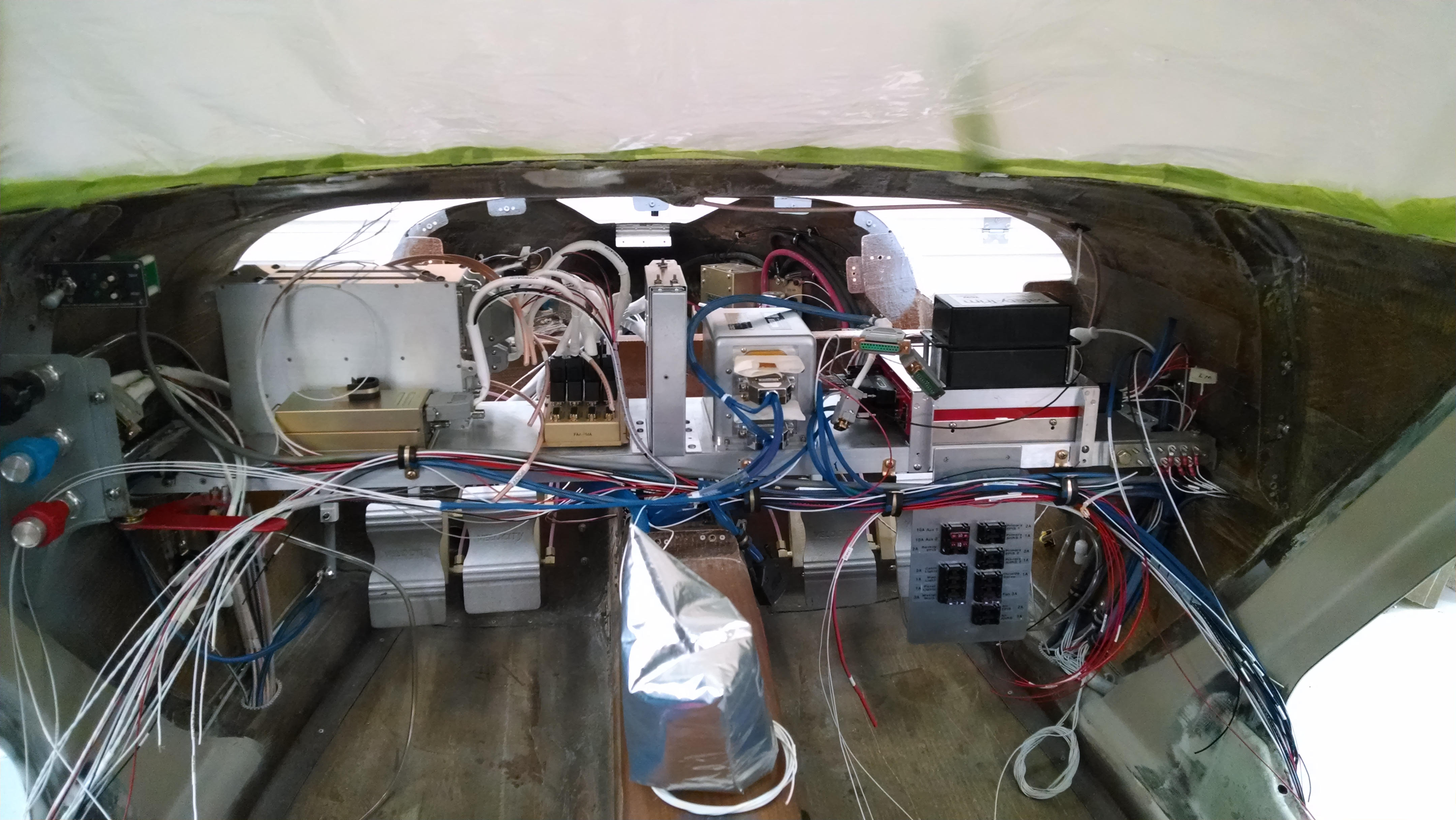
This is the view from the front of the plane. You can see that I’ve re-oriented the audio panel 90 degrees and mounted it just forward of the Com and Nav radios.

Fast forward about two months and I get a box from GRT with my shiny new IFR GPS!  So I moved the audio panel for nothing.  But that’s okay.  No reason why it can’t stay in it’s new location, right?

Wrong.

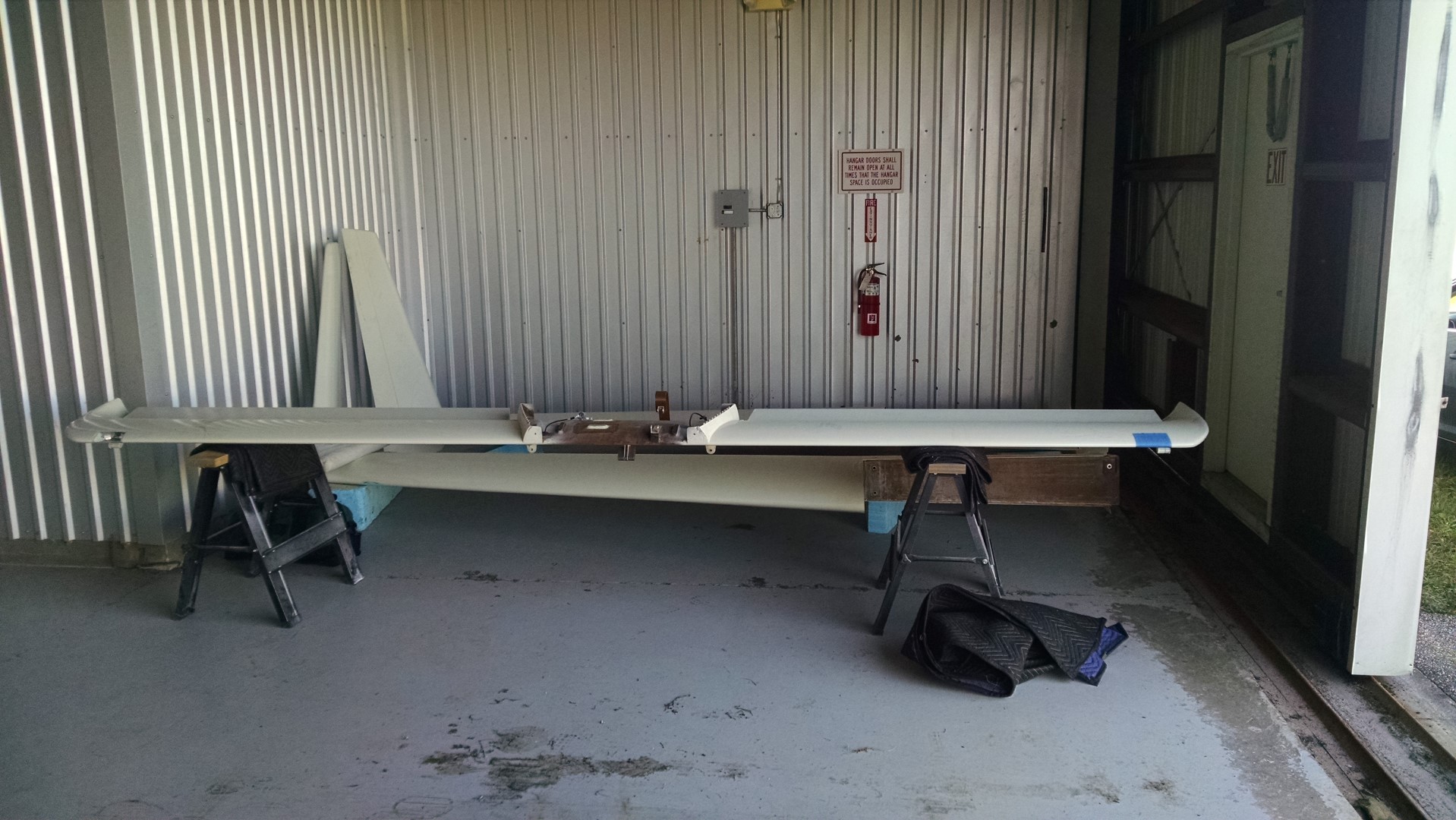
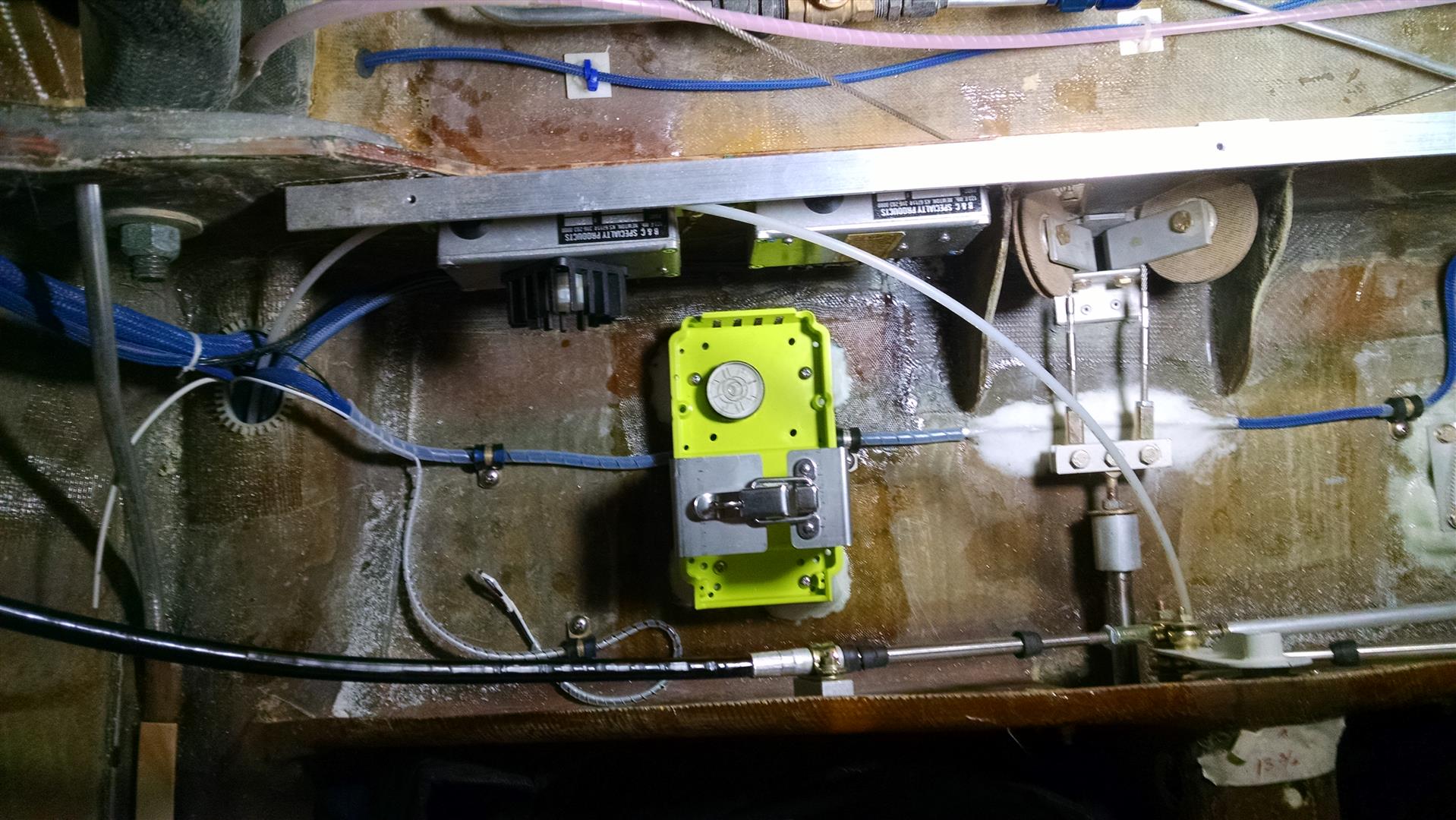
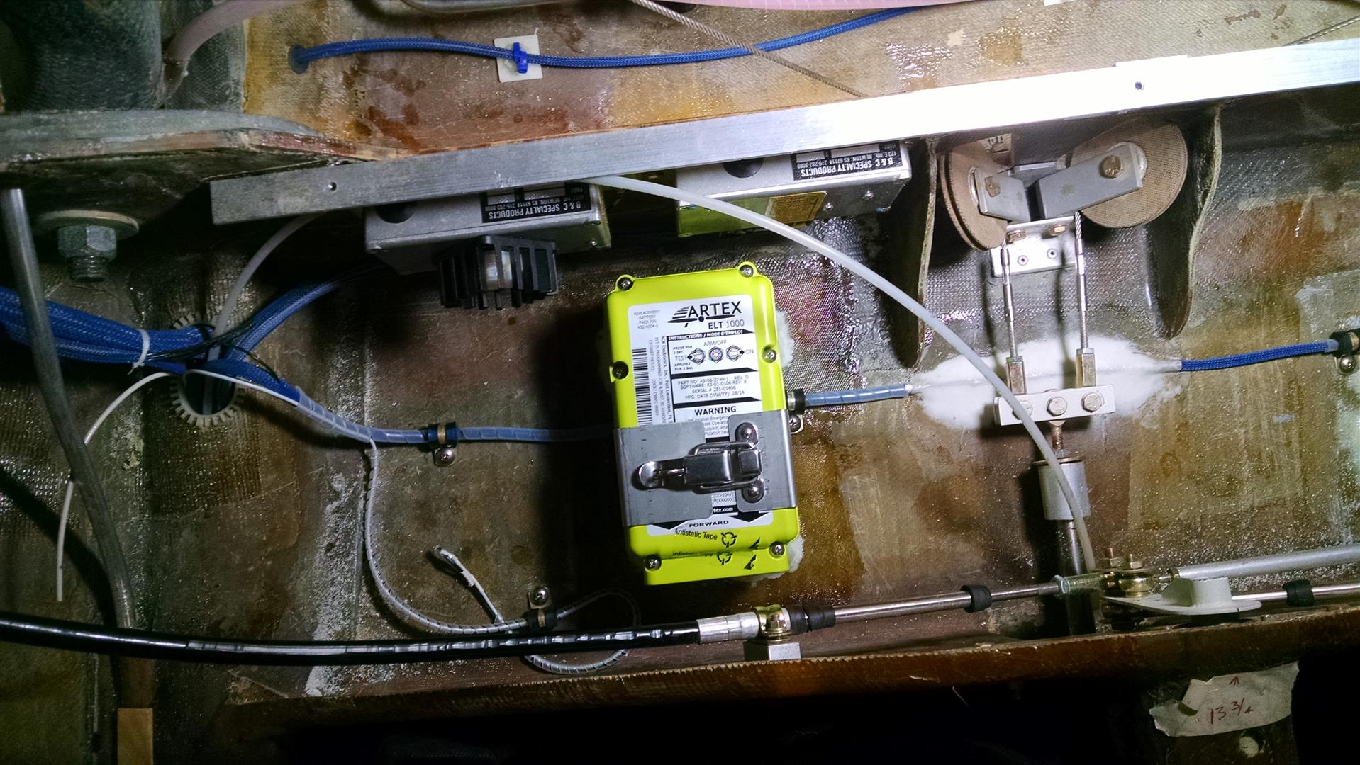
One of the first things that I did once I got down to Sebastian was mount the wings and canard. Once the canard was on, I realized that I hadn’t considered correctly estimated the pitch trim spring area of movement.  The upper cable of the audio panel is now  interfering with the travel of the spring.  Which means that I’m going to have to move the audio panel back to it’s original position.

Except (at the time) I couldn’t remember why I moved in the first place!  This resulted in many a night trying to remember why I moved that audio panel.  Otherwise I might move it back and realize that there was a good reason I moved it in the first place.

Eventually I searched though my emails and found one to Malcolm (with that picture) telling him that I had moved the audio panel to accommodate a possible install of a GNS400W.

So on the next trip down, I’ll move the audio panel back to the center of the avionics shelf.


Back in the saddle again

This entry is part 19 of 38 in the series 14 - Final Assembly / FInishing

So after a number of false starts, it looks like I’m back.

There were some issues as to where the plane would end up.  But after 3 months, it looks like that’s resolved. So last Sunday I drove down (6.5 hours) to Sebastian from Panama City.  🙁

On Monday morning, I enlisted Malcolm (Who’s back down in Sebastian now) to help me get all the boxes of supplies, parts and tools moved into the new digs. Here’s the hangar with the plane that I really haven’t seen for 3 months.

2014-12-15 IMG_20141215_112829170 (Large) 2014-12-15 IMG_20141215_112838110 (Large) 2014-12-15 IMG_20141215_112851189 (Large)

Once everything was moved in, Malcolm started an inspection to create a “punch list” while I unpacked boxes. Within a couple of hours, he had two full pages of todo items. Most of those items (probably about 75%) involved replacing non-locking nuts with locking nuts.  During assembly, there is a lot of installing, removing, installing, removing… So in those circumstances, jam nuts are used since lock nuts can only be installed so many times before they have to be discarded.

So on Tuesday, we began in earnest to start checking off items from the list. By Thursday, we had most of the items done and it was time to install the prop and wings (permanently with locking hardware).  Before installing the wings, I had to mount the nav/strobe lights and terminate the wires for that and the nav/comm antennas.

2014-12-19 IMG_20141219_102511318 (Large)

For the wingtip light wires, I used a nice weatherproof AMP connector and for the antenna wires, I used a male connector for the com and female for the nav.  That way there’s no way of mis-wiring the antenna wires.

On Thursday afternoon, we had the prop on.  By quitting time on Friday, the both wings were on and the punch list was much shorter.

2014-12-19 IMG_20141219_170901832 (Large) 2014-12-19 IMG_20141219_170840902 (Large)

2014-12-17 IMG_20141217_083024900 (Large)2014-12-17 IMG_20141217_083036202 (Large)

A lot of progress for the week, but now it’s time for another (hopefully shorter) hiatus. Christmas and then a week visiting our son in Montana.  Hopefully on the second week of January I’ll be back at it.

My plan is to find some type of transportation to leave in Sebastian so that I can fly the Cessna down.  It’s only 2 hours enroute that way as opposed to 6.5 hours.  I did some scouting but couldn’t find anything cheap.  So the next trip may be another drive. 🙁

Major items left to do are:

1) wheel alignment2) Connect all control surface links
3) Relocate audio panel


00 Heading to Mecca

This entry is part 19 of 28 in the series 00 - Prep/Logistics

So we got moved down to Panama City, FL the first week of September. Then there was a diving vacation in Cozumel about a week later (was planned previously).  The last full week of September I flew Delta to Chicago to bring the Cessna down (got a hanger at Calhoun County Airport which is about an hour drive away).

Yesterday I picked up a small u-haul trailer and loaded up my tools, parts and supplies. Tomorrow I’ll make the 6.5 hour drive to Sebastian and begin (what I hope is) the final push.  I’ll only be able to stay a few days before driving back.  At some point soon, Ann will drive down and I’ll fly down in the Cessna. Then we’ll both fly back.  That way I’ll have a vehicle down there while working.


13.1.9 ELT Installation

This entry is part 42 of 67 in the series 13 - Electrical / Instruments

While at Oshkosh, I decided to get an ELT. I wanted one with a built-in GPS so I wouldn’t have to run a wire from the primary GPS to the back of the cabin. I stopped at Artex where they had their latest unit, the ELT1000, on display. I asked the rep if this new ELT required a GPS and was told “no”.  As a bonus, if you bought the unit at the show, you also got a handheld ELT with integrated GPS. Cool!

So I bought one from Dewey and Pacific Coast Avionics.

I got back to the shop and decided to mount it between the gear bulkhead and the whaletail. So I used some leftover aluminum stock for hardpoints and glassed them in using the mounting base to keep them in position and the ELT level.  2014-08-01 IMG_20140801_080951435 (Large)

Then I glassed over the hardpoints with 2xBID.

2014-08-01 IMG_20140801_080749709 (Large)

And here’s the ELT secured in place.

2014-08-11 IMG_20140801_081114820 (Large)

Then it was time to pull the cables to the control head. That’s when I discovered the problem.  There were two wires that were identified as “GPS signal”!?!?  And I couldn’t find an antenna connection for the GPS antenna.

So I called Artex.  The first person I spoke to said that the unit definitely comes with an internal GPS. When I asked about the GPS antenna, they said “let me ask someone about that”. I got transferred a couple more times and finally got the head of sales. He told me the unit does not have an internal GPS and that there was no way any of his people would have said that. Yeah… right.

But he did step up and say that if I wanted to return it for a full refund that I he would contact Dewey to make sure I was taken care of.

So contacted Dewey to see what other options were available. After a evaluating the options, I decided to keep the ELT and run a couple wires up to the panel. It would cost more for an ELT with a GPS and I already had the mount installed anyway.

So I pulled a extra wires and mounted the remote control head in the panel.

IMG_20140826_104320680 (Large)_20140826_094334 (Large)

For the antenna, I considered an foil dipole on the floor or ceiling but if there were a crack in those locations, it would diminish the signal. So I decided to use the provided whip antenna. For the location, I went with the right side between the gear bulkhead and the whaletail. Mounted vertically, it would be hidden by the box for the vanity panel.  I made a ground plane that had a radius of 7.29″ (406MHz wavelength of 29.17″ / 4 = 7.29″) and mounted the whole thing under the baggage shelf.

IMG_20140813_085241198 (Large)

When the side boxes are on, it’s out of sight.

2014-06-18 IMG_20140618_131438203 (Large)


00 Moving

This entry is part 14 of 28 in the series 00 - Prep/Logistics

The plan was to move the Velocity to the Lake In The Hills Airport (3CK) sometime around June. Then the wings and prop would be installed, the engine started and taxi testing would begin.

But we’re moving to Florida.

This has been on the horizon for a while but I was hoping to finish before the move took place.

Now the big problem is that there is no hangar space in Panama City, FL (and the hangars they do have are double the cost of my Chicago area hangar… go figure that out!).  I’ve been on the waiting list for about a year and so far nothing.

There’s an airport with hangar space about an hour NW of Panama City, but if I moved the Velocity there, it would be an hour drive each way and I would have no resources at that field (at 3CK, I’ve got an A&P/IA, avionics tech and some other people that I know who I can call on for help).

So we made the decision to move the Velocity to Sebastian, FL. That way, I will have the resources of the Velocity factory, transition training will be easier and when it’s time for the first flight, I won’t have to fly John Abraham (test pilot) out to Panama City.

Of course the down side is that I’ll be spending 5 days a week in Sebastian until I’m done. 🙁

Travis is scheduled to arrive on the 28th of this month to pickup the Velocity and transport it down to Sebastian. We’re going to be loading up the truck and moving down to Panama City around the 3rd or September.

So for the past month or so, I’ve been trying to get as much done as possible and prepping the plane for transport.

14.2.3 Final Prime of the Cowling

This entry is part 18 of 38 in the series 14 - Final Assembly / FInishing

Malcolm suggested waiting until later to do the final prime of the cowling because it can get banged up putting it on and taking it off. Since I’m moving the plane, I figured that I should get it done as I may not have the facilities where it’s going.

I did some final sanding and filling on the top and riveted the oil door and filled the rivet heads. Then set the cowling outside and sprayed. About an hour later a very isolated shower came through and put some big craters in the primer. 🙁

So the next day I sanded it down and primed it again.

2014-08-20 IMG_20140820_200129914 (Large)  2014-08-20 IMG_20140820_200102964 (Large)IMG_20140826_113755737 (Large)

On retrospect, I’m probably going to remove the oil door and use nutplates with flathead screws on the cowling side of the hinge. It’s just really difficult to get good coverage of paint under the door.

12.99 Induction Air

This entry is part 41 of 50 in the series 12 - Engine / Propeller

In a standard Continental IO550N installation, the way the engine gets air is through a “U” shaped duct that takes the rearward facing fuel injection servo and points the intake forward (remember the engine is in backwards).  Since I’m going a different type of plenum, that part won’t work for me.

An added issue is that the air is pulled directly from the upper area (which is supposed to cool the engine as it is pulled down) and there’s NO AIR FILTER!

So I had this idea that I would make a NACA duct on the bottom, put an air filter down there and somehow create some ducting to get that clean air up to the top of the engine.

I started with the part that I thought would be hardest. Making the ducts to get the engine intake extended to the lower cowling.

So I used a trick that I learned from Malcolm for fast prototyping. Using some leftover blue foam, I made a slightly smaller version of the duct. Malcolm’s next door neighbor builds funny cars and has a lot of experience moving air to 1,000+      horsepower engines. He said that squaring off the outside radius of the turns improves the airflow. So I squared off the outside part of the turns.

_20140709_162434 (Large)

The next step is to cover the foam with duct tape. But with the curves on this part, that didn’t work too well. So I used electrical tape instead. Because it’s softer, it was able to make the turns better. Then I smeared vasilene over the part and covered it with 4 layers of BID.

Once the epoxy cured, I poured acetone through the part which dissolves the foam. Then you just remove the tape and you’ve got your part.

IMG_20140724_064107520 (Large)

The next part is the elbow to turn towards the lower cowling.  By comparison, this is an easy part to make. Once again, I squared off the outside radius.

Then I cut a hole in the aft baffle and joined the two parts with a friction slip-joint. I added a tab to assure it would stay in place.

IMG_20140726_073803973 (Large)IMG_20140726_073756481 (Large)

All in all, I was feeling pretty good.

I picked up a 11″x6″ K&N generic air filter from the auto parts store, measured it and (this time) used plywood to make the mold for the filter box.

This would connect to the NACA on the lower cowl. Then I would make some ducting to get the air up to the elbow.

And that’s when I figured it out… There’s just no room! The amount of space between the engine (and engine mount) isn’t big enough to allow for a submerged NACA.  Let alone the almost 4 feet of ducting to get it up to the engine. I spent a lot of time researching various solutions but I just couldn’t figure out a way to make it work and not lose any performance.

So I had to drop back and punt. I made a U and I’ll pull air from the upper plenum without a filter. 🙁

IMG_20140809_181956766 (Large)IMG_20140810_172101357 (Large)

I went ahead and painted it so at least it looks pretty.

_20140818_162112 (Large)

5.3.6 Door Pin Sleeves

This entry is part 13 of 16 in the series 05 - Doors / Windows

The sleeves that the door pins go into have been something that I’ve been thinking about for a while. They are not only ugly, but they have a tendency to catch clothing when entering and exiting.

2012-05-23 IMG_20120523_092117 (Large)

Some builders have made aluminum plates to cover them. I tried that, but getting the hole drilled at the compound angle was proving difficult.

So I decided to try a somewhat artistic approach (even though that is definitely not my forte).

I mixed up some epoxy with cabosil and a little milled fiber and moulded around the sleeve. When it cured, I sanded it and then added another layer. Then sanded, filled, sanded and painted.

2014-07-21 IMG_20140721_105914595 (Large)

Not sure how well it’ll hold up, but I haven’t got my shirt torn since.

13.8.1 EFIS alternate power

This entry is part 52 of 67 in the series 13 - Electrical / Instruments

One of the problems with a 28v electrical systems is that some of the goodies that are available for 14v electrical systems don’t exist for 28v.

One of those “goodies” is a backup battery for the EFIS. During engine start, the battery power will drop. If it goes below around 19v, the EFIS shuts down. Now it takes the EFIS about a minute to power up and it displays engine information. So if it drops offline when I start the engine, I won’t know what’s going on with the engine for about one minute.

Grand Rapids sells a backup battery that will keep the EFIS up if the primary power drops off. But it’s only available for the 14v version.

I thought about getting a small 24v, 5amp battery for this purpose, but then I’ve got a deal with finding a place for it, wiring it into the existing electrical system so it can recharge, etc.

TCW Technologies (who make the trim controller) also have, what they call, an Intelligent Power Stabilizer (IPS). As long as there’s about 12v coming in, it will put out a steady 24v. So I purchased one and tested it out. I was able to drop the input power to about 10v before the output dropped below 24v.

I went it install it on my avionics sub-shelf but I realized that I wouldn’t have anyplace for my GPS.

Here’s version 1 of the sub-shelf.

2013-12-06 IMG_20131206_170639_577 (Large)

So I had to add another level to the shelf.

2014-07-16 IMG_20140716_111956488 (Large)

The IPS unit is on the lower shelf. The GPS will go above the IPS on the top shelf.