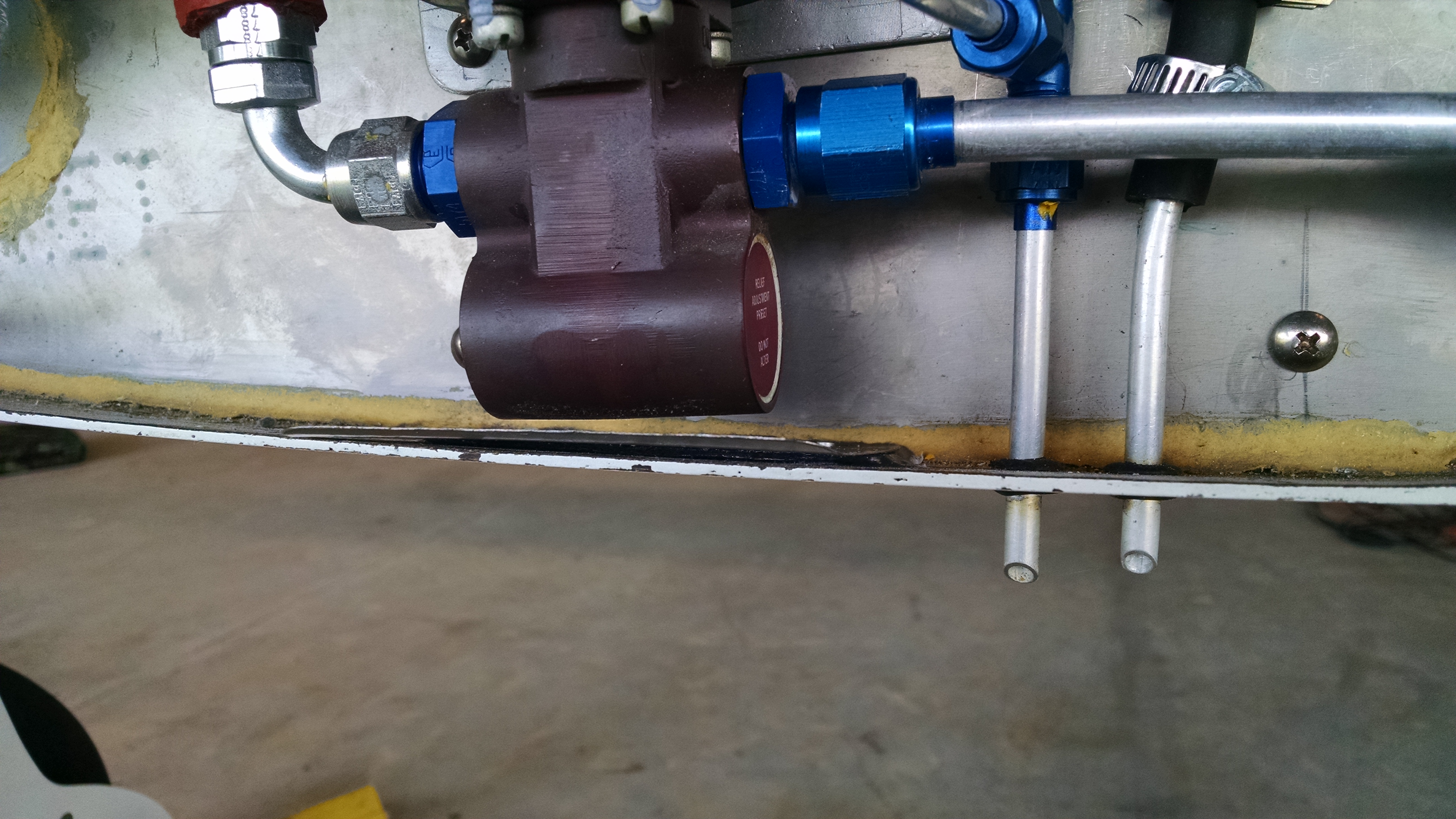
Once I got the new GPS installed, then discovered the fuel system had a bunch of contaminant in it and flushed it out, I wanted to run the engine for at least an hour to verify the fuel system was clean. So I did some low and high speed taxi runs. During those runs, I noticed a shimmy. So I decided to check the alignment.
What I discovered was that I had some negative camber on one wheel and the toe-in was non-existent on the right wheel (actually is had significant toe-out). Read farther down to see how I do a solo alignment check.
Now when me and Malcolm were doing the alignment we had a hell of a time getting a consistent result on the right side. The problem was the gear leg was not flat. So depending on the order we tightened the bolts, the torque value, phase of the moon and so on, we would get different toe-in results. The fix I came up with was to use an epoxy/cabo mix to create a thin, flat pad on the gear leg. Once that was done, we determined that a regular flat washer on the rear bolts gave us the necessary 1″ toe in.
What ended up happening is that the once the brakes heat up, the pad became soft enough so that the washer became embedded into the pad. This may not have been a problem had I used a) large area washers cut down and/or b) placed the washers between the garolite and the axle pad.

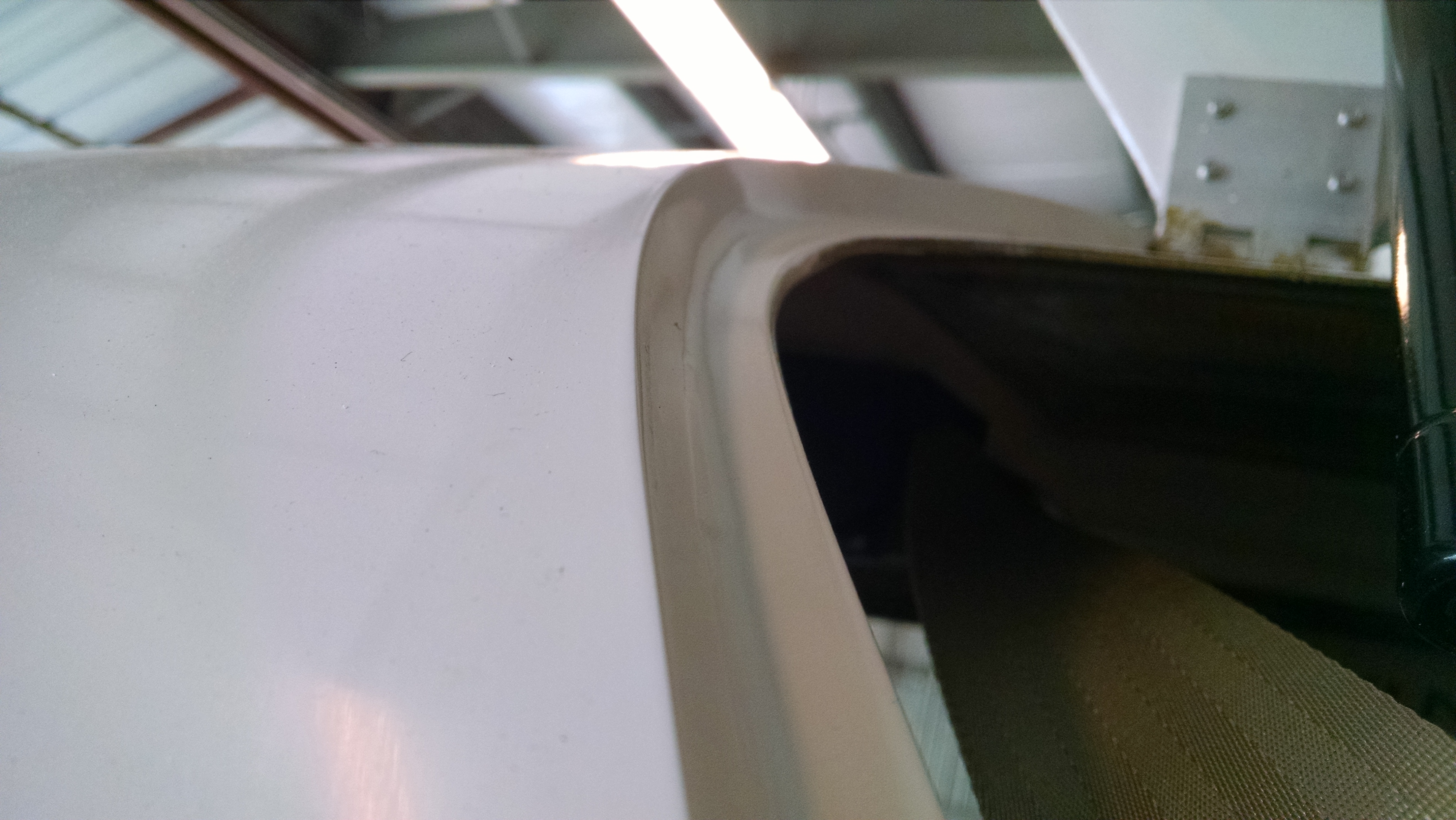
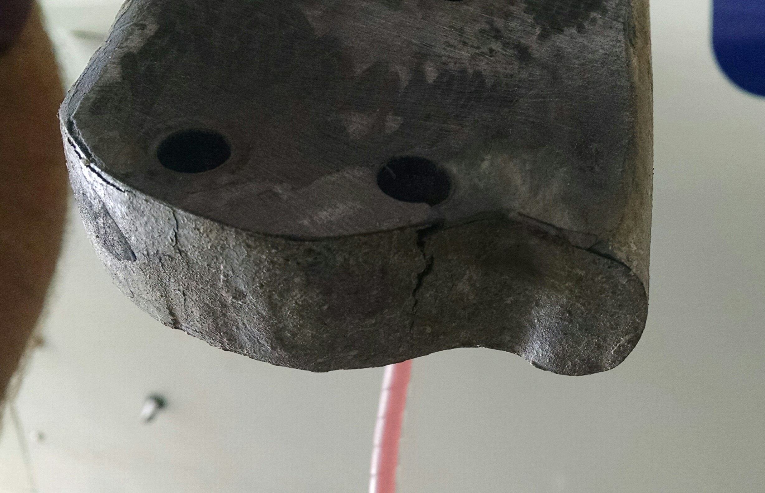
I used my large Permagrit board to remove and flatten the bottom of the gear leg without removing too much of the carbon fiber. While doing that, I discovered some rather concerning cracks from the bottom/front holes to the lower edge of the gear leg.

When I was drilling these holes, I thought they were awful close to the edge, but there’s no way to mount the brakes otherwise. I checked with Scott and he confirmed that the cracks are not unusual given the location. Good thing there’s three other bolts!
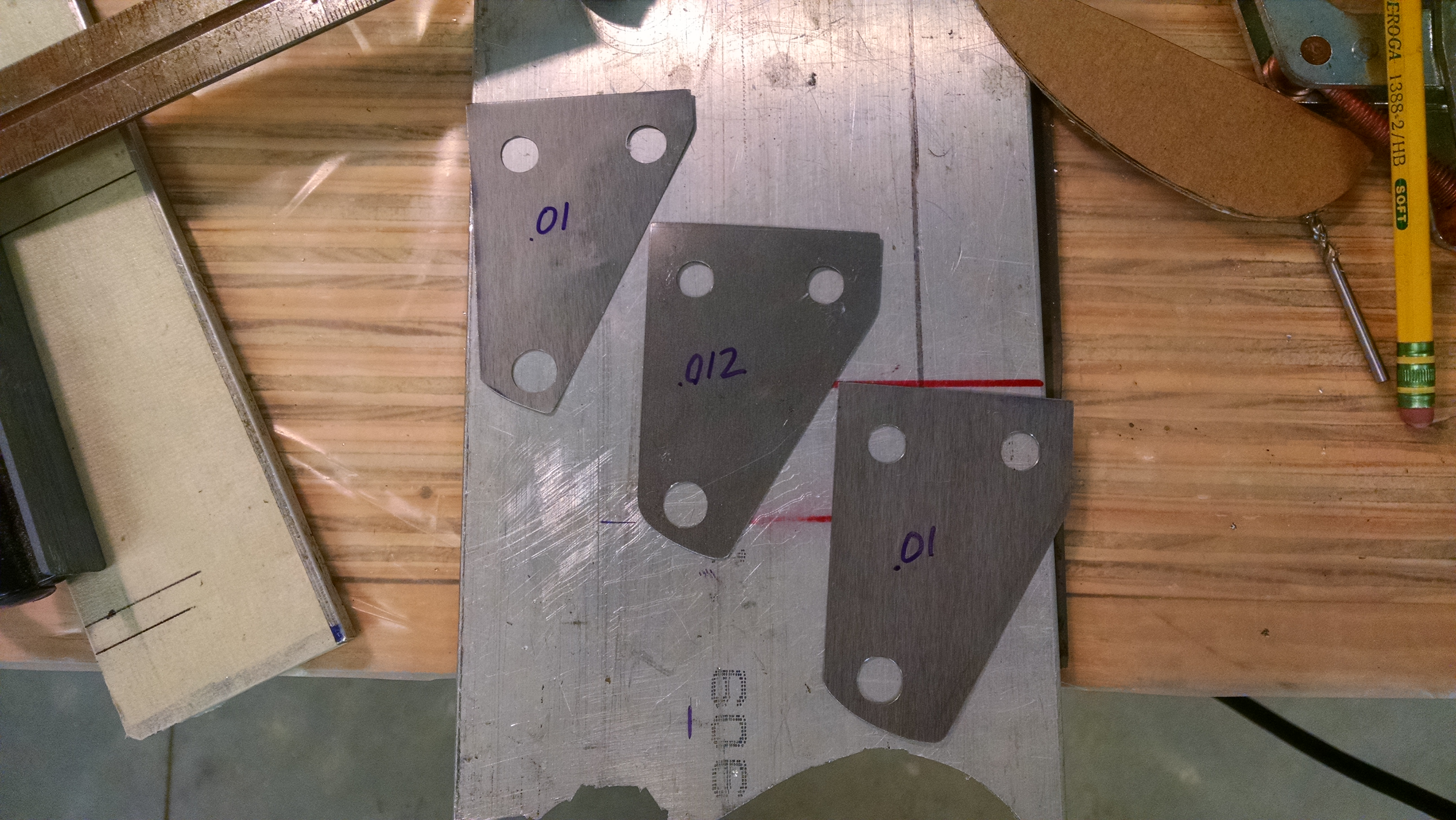
I ordered some steel shim stock from McMaster-Carr for $19. I could have used aluminum that I had laying around but I wanted something that didn’t conduct heat as quickly.
So I put everything back together and checked the toe-in. The general rule is that .010″ of shim will change the toe-in by 1″. But there’s no guidance on adjusting camber.
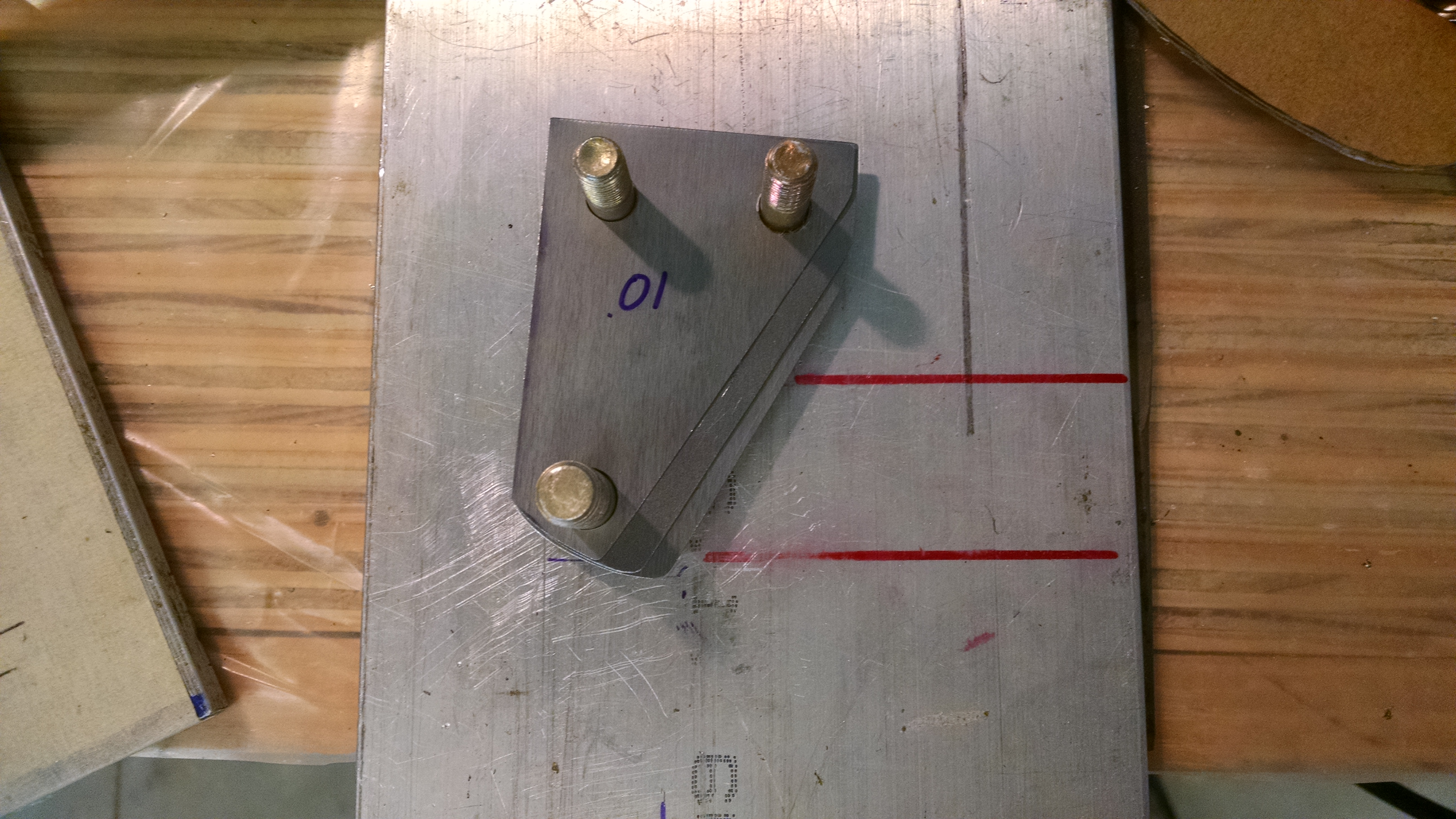
I started with .032″ of shims on the top (to eliminate the negative camber) and rear (to get some toe-in.


Because of the geometry, I also made some wedge shims for the top/rear.
But when I put everything back together, I getting the same behavior as before where the resulting readings where all over the place. So I decided to eliminate the space in the center.

Once I did that, I was getting consistent results. Then I just kept adding shims to the top and rear until I got neutral camber and 1″ of toe-in. It took a few days because at first I was re-measuring everything after every change. Then I got it figured out so that it only took a few moments of positioning (you have to roll the airplane back 10′ and then forward 5-6′ to get the gear properly loaded and positioned.
Checking the wheel alignment solo.
When Malcolm and I were doing the alignment the first time, it was pretty quick because with two people, it’s easy. Not so much with one person.
Here’s the sequence:
- Get the main gear properly loaded and positioned. This is done by rolling the aircraft forward at least 5′. Because of the toe-in, this will move the wheels towards the centerline.
- Establish the centerline. Take some masking tape a place on the floor directly beneath the nose and the center of the prop (or spinner). Drop a plumb-bob from the nose and prop center and place a mark on the floor.
- Using a string (or laser) connect the mark on the floor at the nose with the mark and the tail. This is your centerline. Now the nose wheel is in the way for this step. There are two workarounds: a) raise the nose and put two small wood blocks on either side of the nose wheel leaving a space for the string. b) make a mark 3″ to the right (or left) of the actual nose and tail marks. When you do this, you will have to adjust the next step 3″ to identify the centerline.
- Place a piece of masking tape about 7″ forward of the main gear axles and mark the centerline.
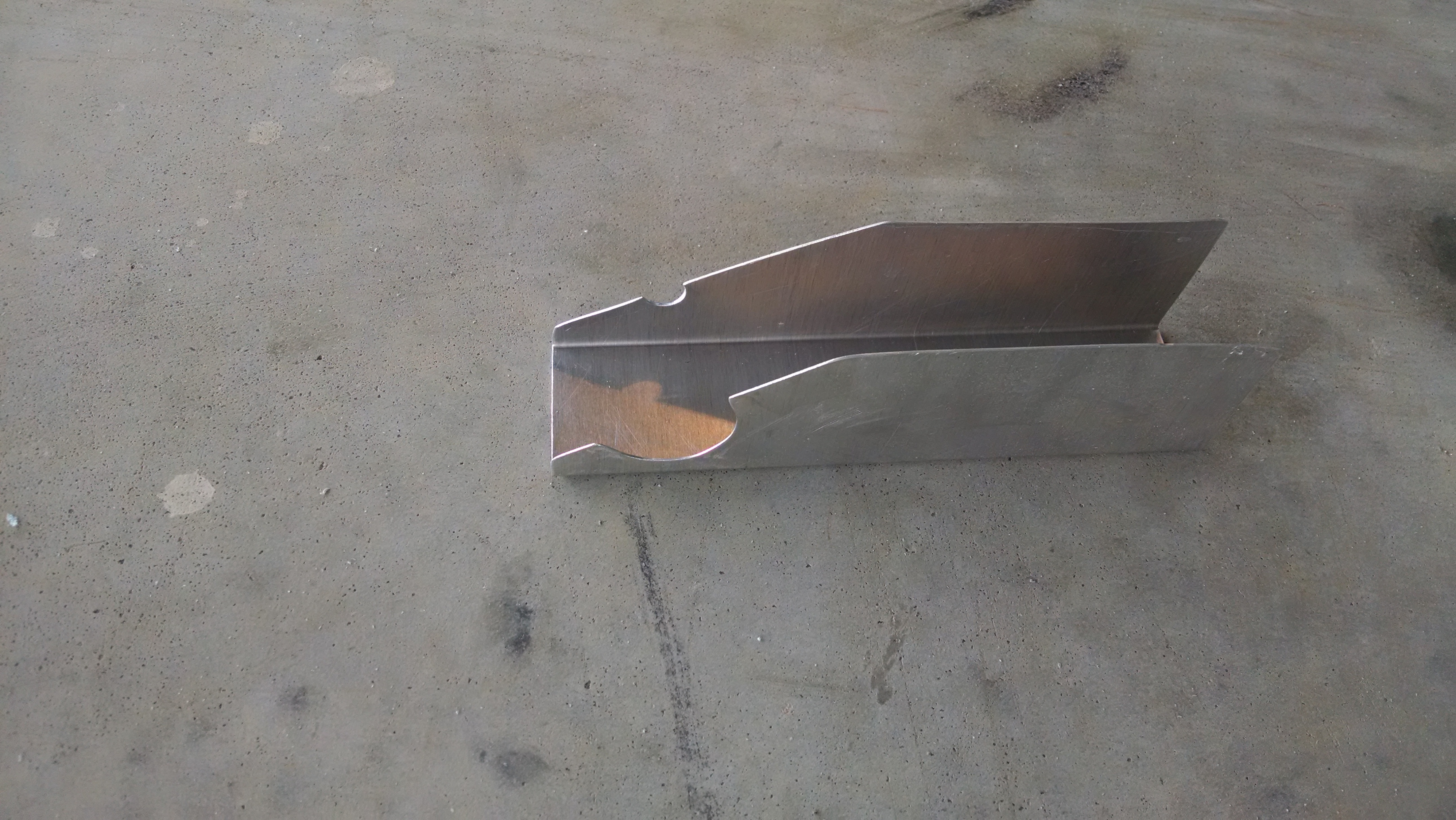
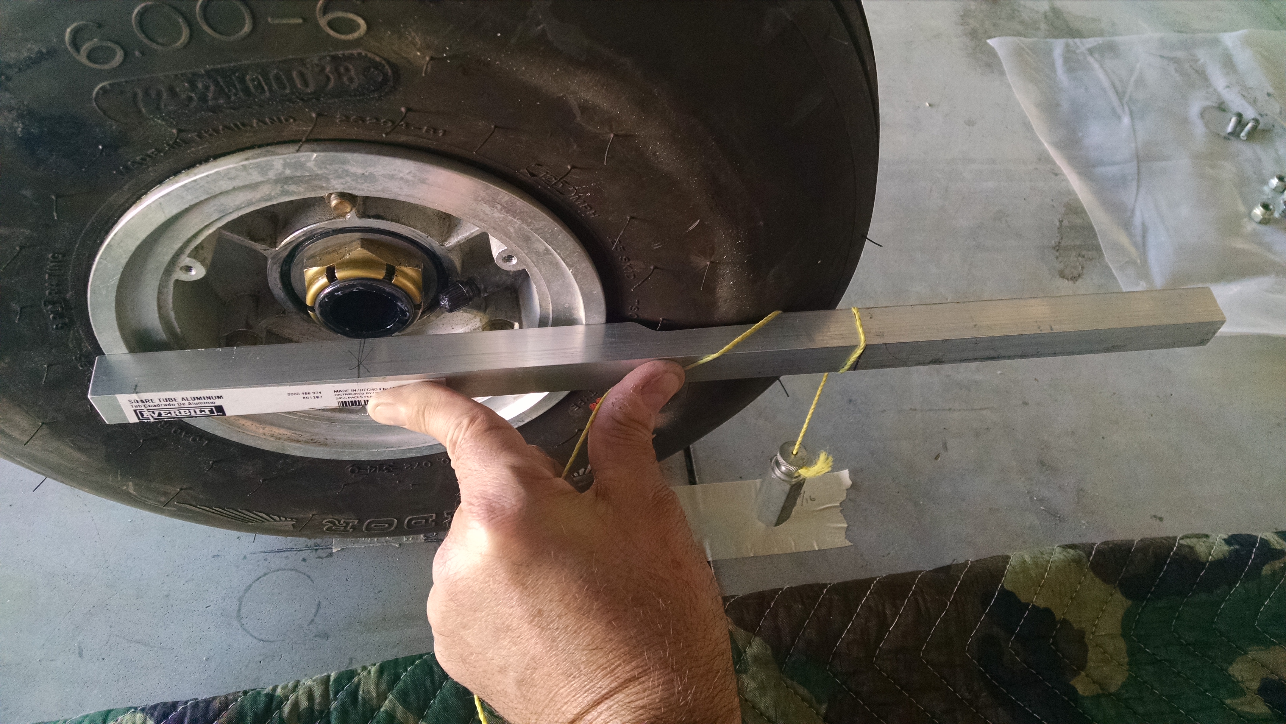
- Mark the location of the outside of the wheel (not the tire) 7″ forward of the center of the axle. There are a couple different tricks to accomplish this. I used a piece of scrap 1″ square stock with a notch for the tire. Then using a plumb-bob, place a mark the floor (actually, the masking tape on the floor). Do this for both wheels.

- Measure the distance from each wheel to the centerline mark and write this down. Do not be surprised if the two numbers are not identical.

- Measure to the left and right of the nose mark and place marks on the floor that correspond to the distances you recorded in step 6. I placed a strip of tape marking a one inch intervals.
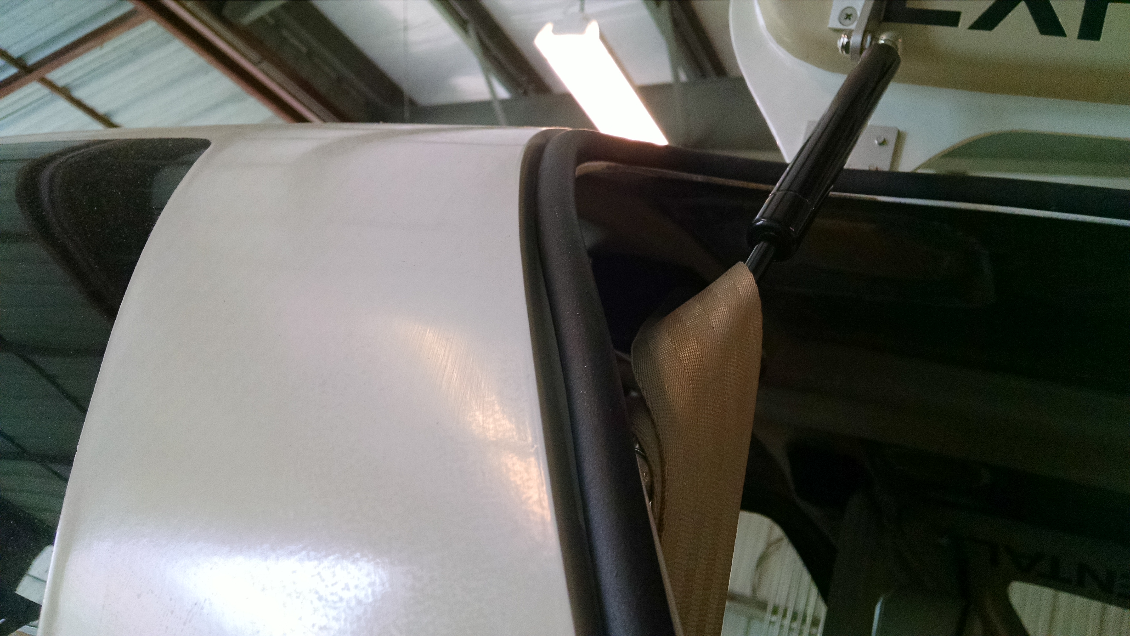
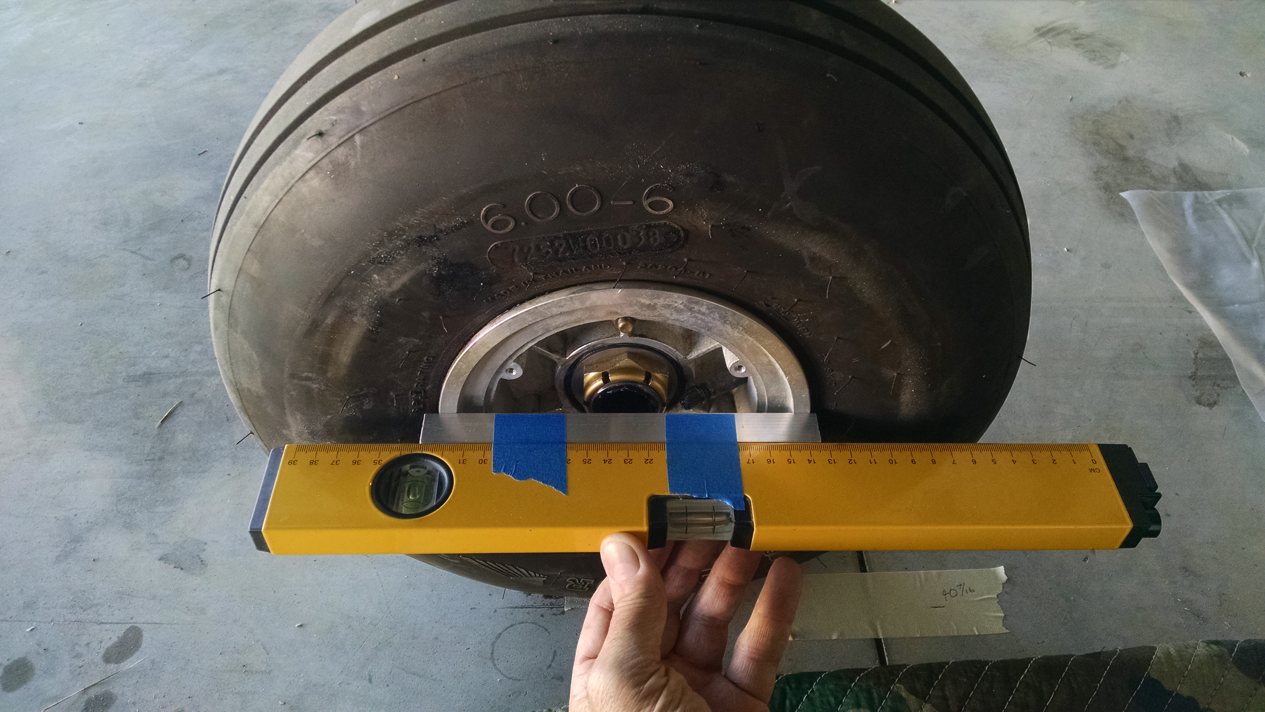
- Now we have to project a line from the wheels to the front. The manual uses long aluminum I or box beams and deflating the tires so the aluminum will contact the wheel and not the tire. What I did was to take a piece of 1″ square aluminum stock to it that was just long enough to span the wheel rim and tape that to my laser level. Now I can shoot the laser up front.

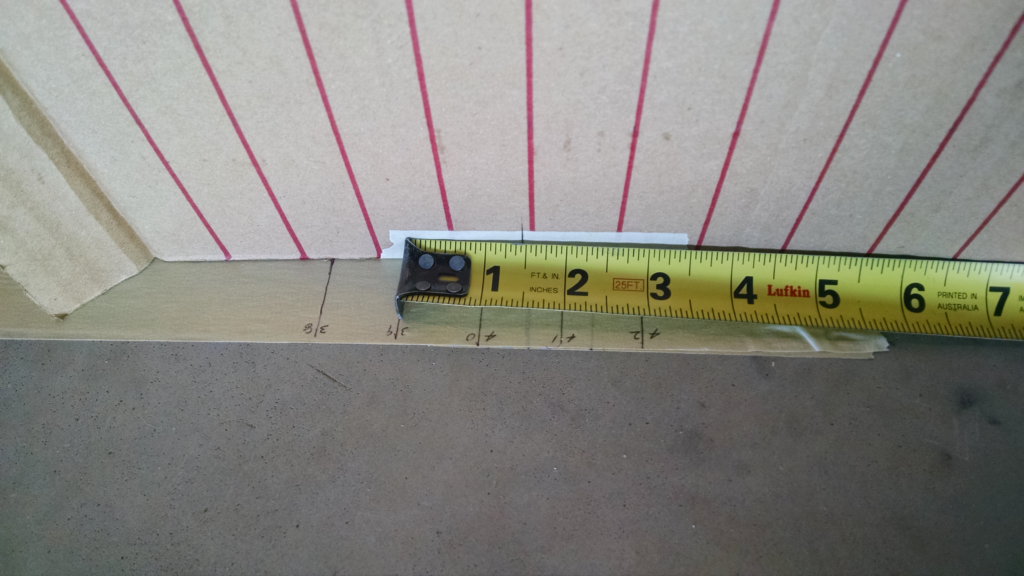
- If there was another person, they could use a tape measure to see if the laser dot was 1″ inside of the mark on the floor. Since I was alone, I made a target out of cardboard. I drew vertical lines that were 1″ apart. Then I placed a mark on the cardboard 1.15″ inside of the zero line (that is the distance from the 1″ bottom of the 1″ square stock to the laser. Place the target on the floor so that the reference mark is on the spot on the floor and now you can shoot the laser at it and see if you have the correct toe-in. My laser also has a flat line option so I can use that to check the camber as well. But that line is rather dim so I have to make the hangar somewhat dark to see it well.


- Final, successful results