One of the changes I made during my build was to replace the screws which attach the doghouse cover to the canard with piano hinges with pins that are removed from inside the nose.
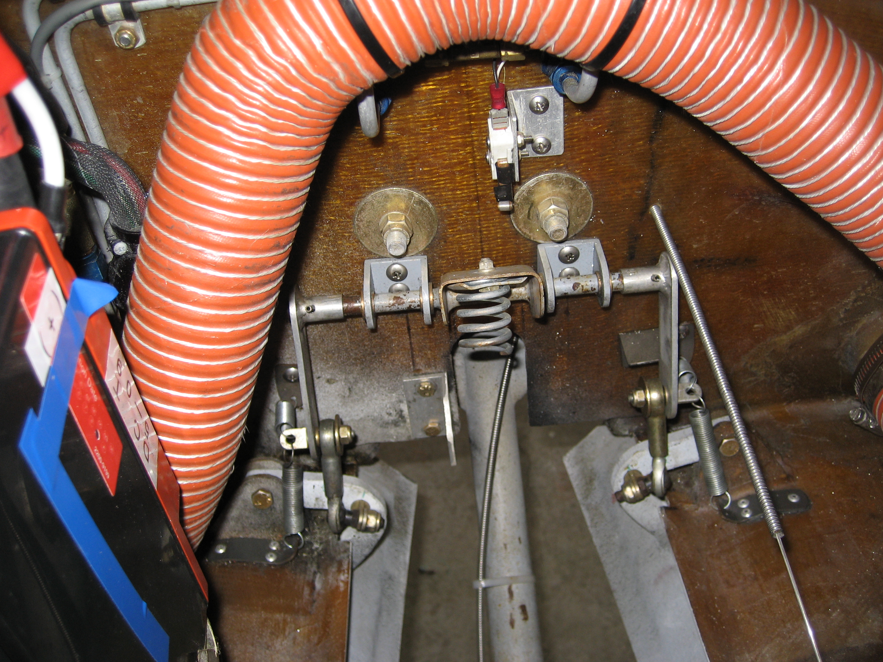
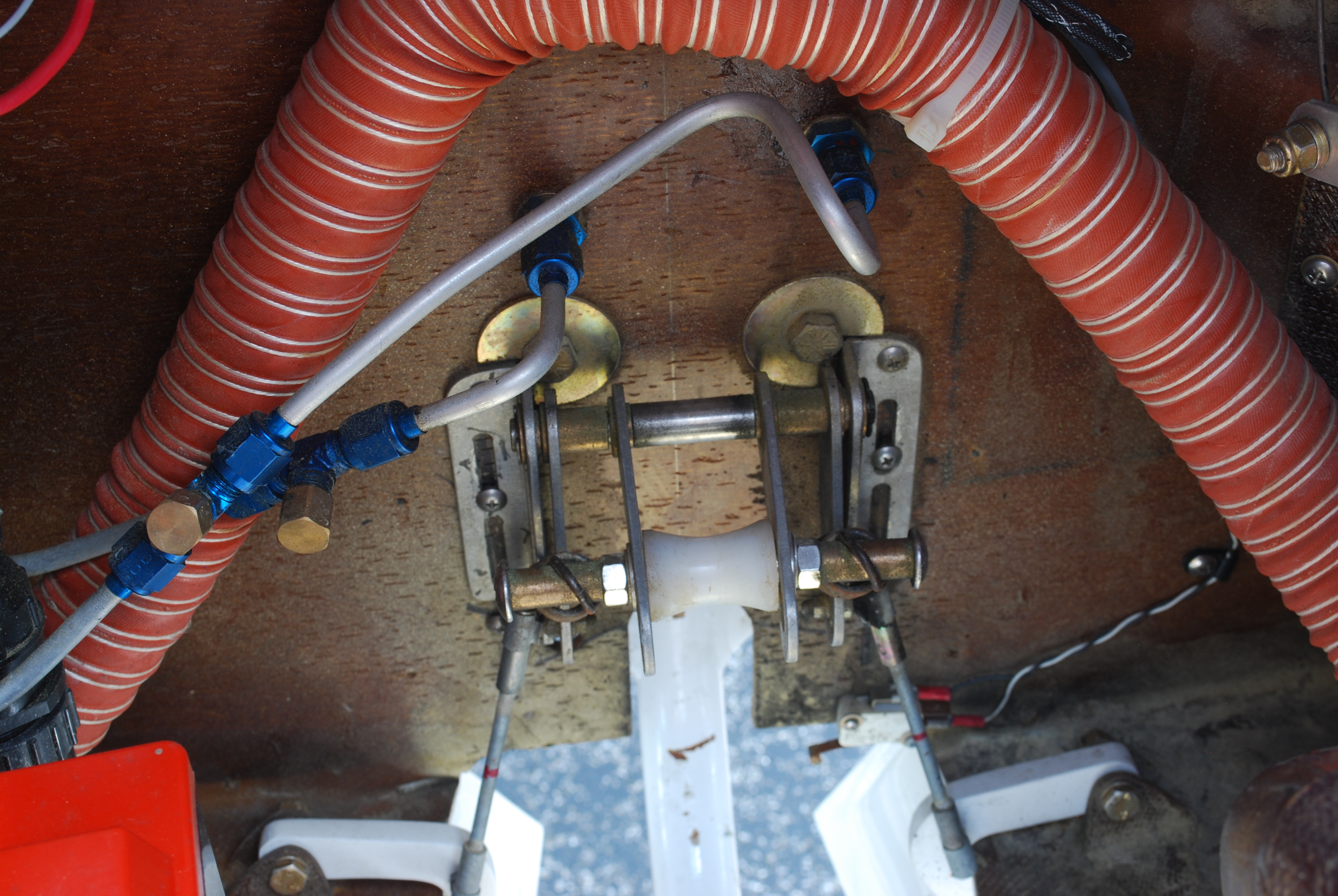
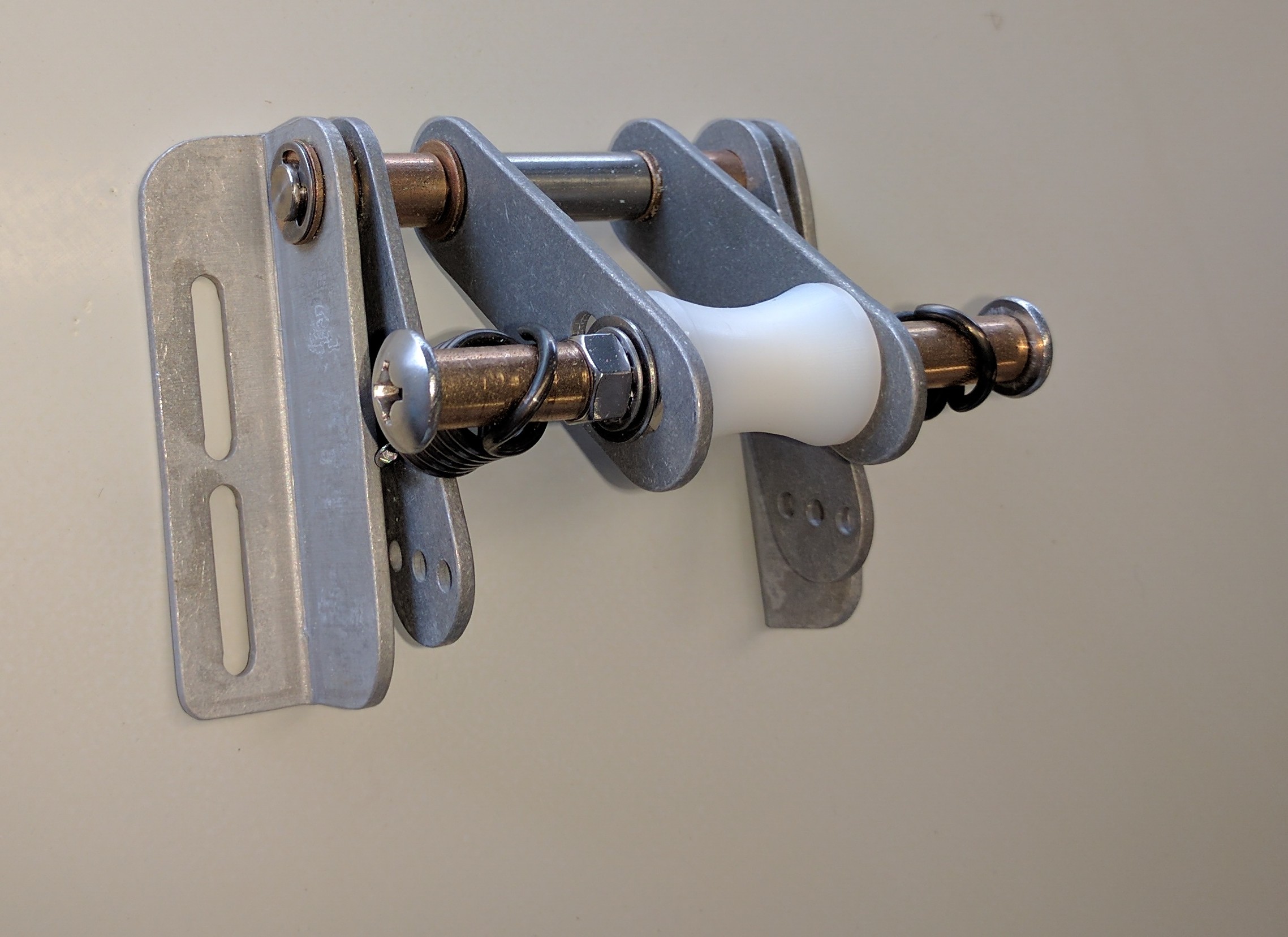
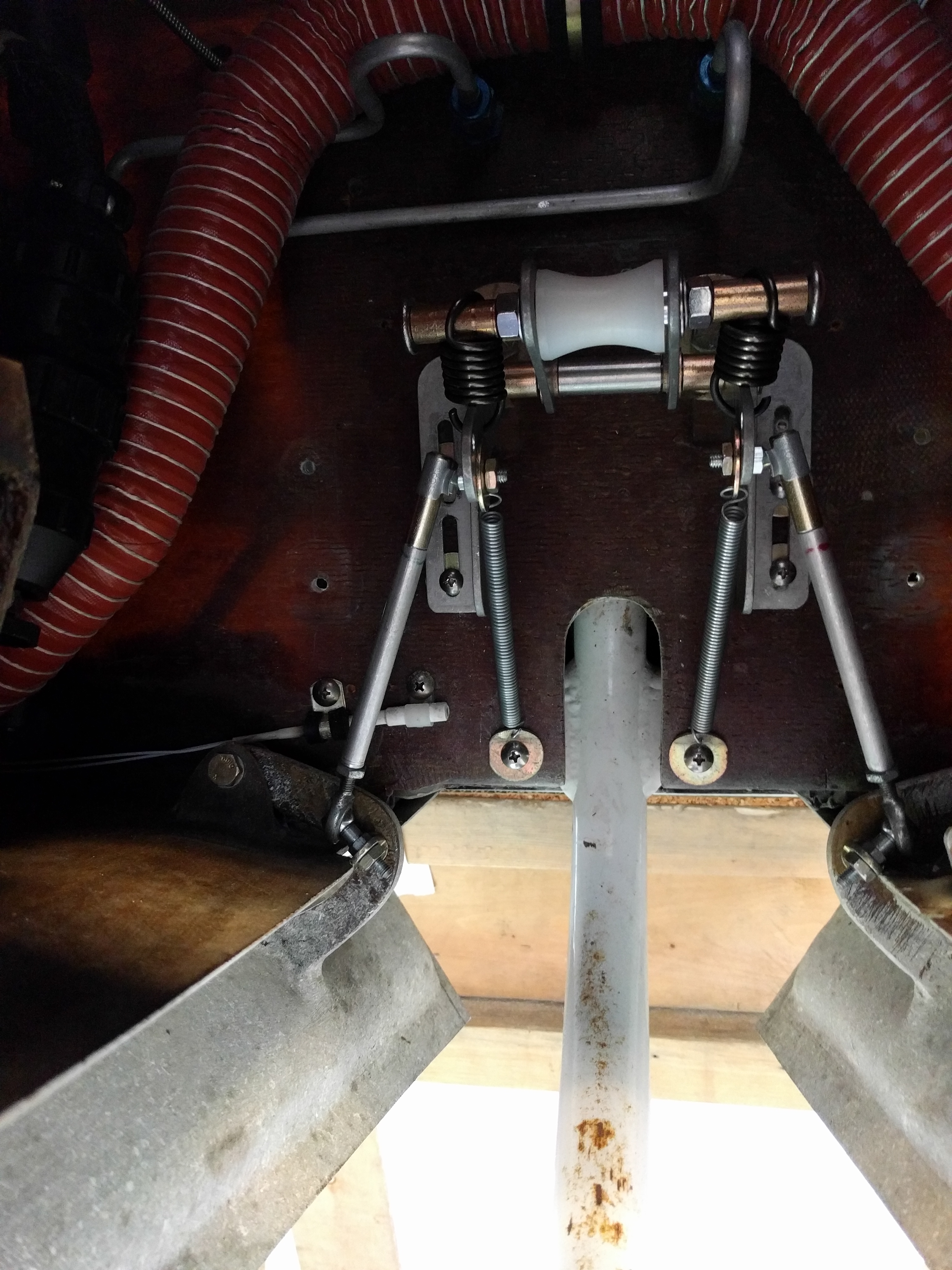
6.8.2 Doghouse Attach Points
I also used an internal J-hinge for the nose hatch and a hidden latch. This means there are no visible screws on the forward part of the aircraft.
When the cowling was being prepared, I considered using piano hinges there as well. But three things stopped me. One was that I couldn’t figure out how to deal with the cowl to fuselage attachment. I knew from experience that the slight curve of the hinge for the doghouse cover made for a bit of challenge getting the pin to slide into the hinge easily. The fuselage curve would be significantly more difficult.
The second was how to access that cowl-fuselage pin. There would have to be some type of hole in the cowl to insert the pin and you need a latch of some sort. Malcolm said he built one and that it was inserted from below the wing and you had to use a drill to get in fully inserted.
And the third was time. At this point I was about 5 years into the build. The plane was at Hangar 18 (Malcolm Collier’s shop) so I was commuting from Chicago to work on it. The engine hadn’t been hung yet, the first electrical wire had yet to be pulled and I was looking to get finished. So I made the decision to go with the method called out in the manual which is to use screws with nutplates to attach the cowling.
I used #8 truss head stainless steel screws. I picked up some nylon washers to try and keep the cowling finish somewhat presentable.
And it works. There’s nothing wrong with the book solution.
But like many aspects, it could be better. In my opinion, the biggest drawback is time. There are a little over 40 screws holding the upper and lower cowling in place. I eventually purchased an electric screwdriver to speed up the cowling removal process. But even with that it still takes a long time to remove all those screws. The heads of the screws round out. Which means I had to constantly replace screws when the head became so damaged that I couldn’t tighten it anymore. Finally, it just looks… not bad… but not good.

What alternatives are there?
Piano hinge retrofit
I could use piano hinges on the wing roots and where the two cowl halves meet. Then the screws would just be at the cowl-fuselage junction. The problem with that is trying to install hinges with the engine in place would be very difficult if not impossible.
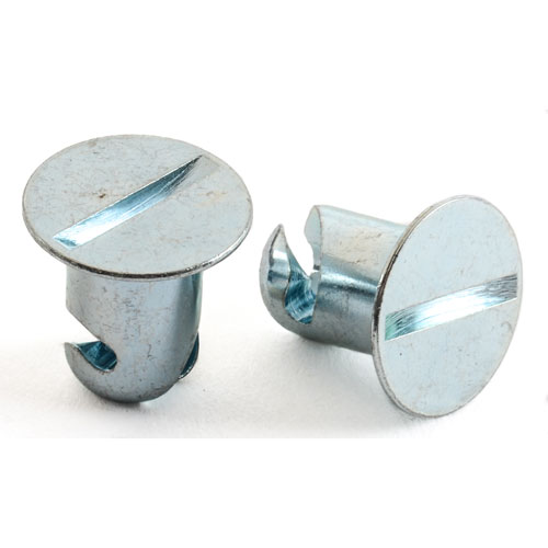
Camloc’s, Dzus or quarter-turn fasteners
These have been around airplanes for years. Basically they are spring loaded, quarter turn fasteners. They are available in many styles. The problem is that they aren’t cheap. But I found the racing version isn’t too expensive. So I got a couple samples.


The spring gets riveted to the underside of the lower panel. Then the fastener gets inserted from the outside and picks up the spring. But here’s the big problem: This would be fine with a sheet metal airplane where the thickness of the panels doesn’t vary. But with a composite airplane, there are variations in the thickness of all the parts. So you would either need a number of different length fasteners. And of course you would need to remember which length went in which hole. Or you could measure and then use shims to create an identical thickness. The other issue is that they are HUGE. Some of the heads of the fasteners are one inch in diameter.
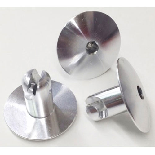
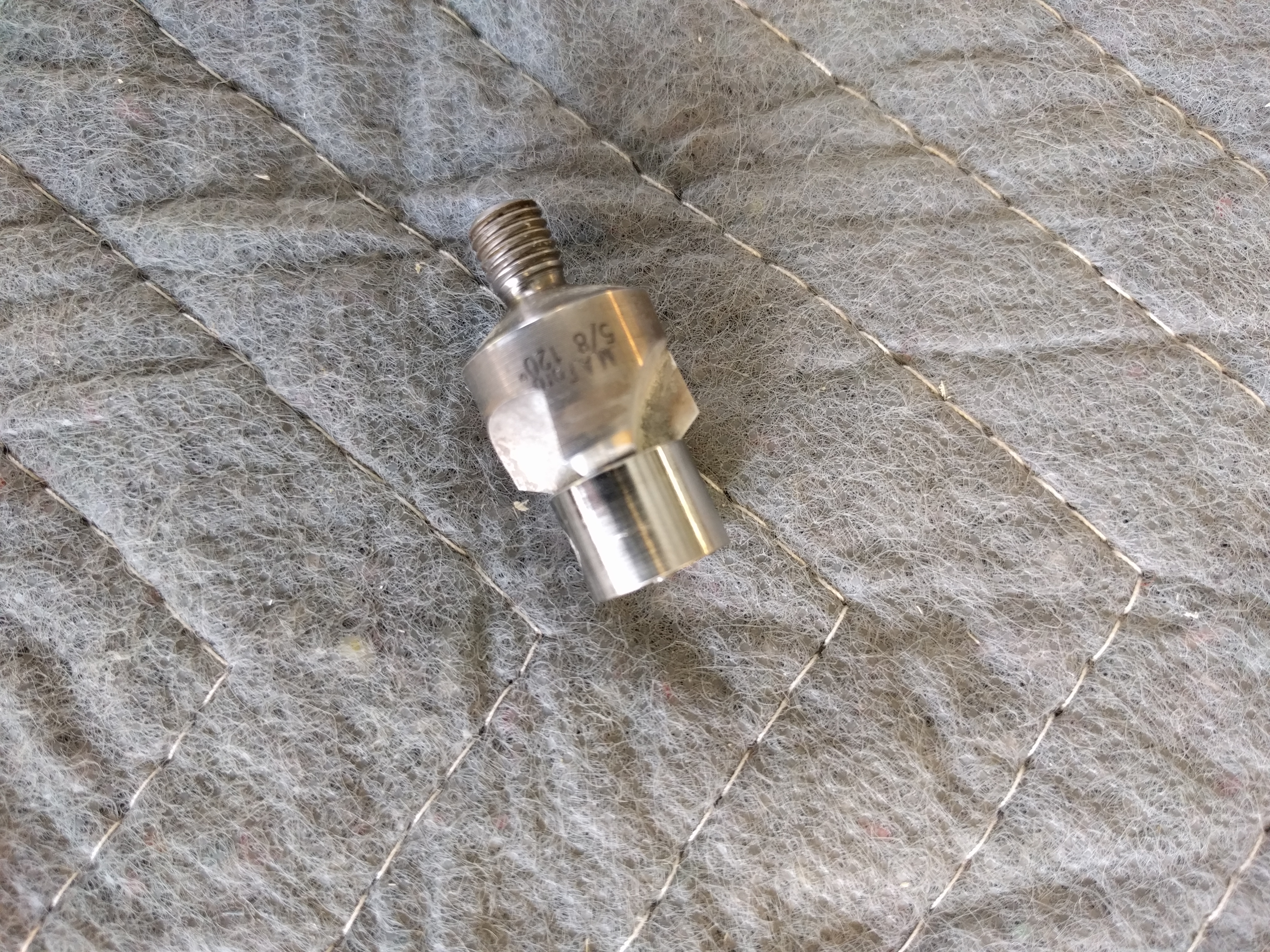
Then I decided to look into aircraft versions. Reiff Lorenz gave me a tip for Skybolt located nearby in Leesburg, FL so I started looking at their offerings. They have a number of different types. But the one which has the most promise is their Cloc 4000 Series Fasteners. The best part is they have an adjustable receptacle (like the nutplate for quarter turn fasteners) which can accommodate a wide range of panel thicknesses. I ordered two fasteners, two floating receptacles and two grommets. The grommets are the ring that the fastener goes through on the outer panel. Kind of like a bezel.
I tested them out on some mockup panels and they work great. I simulated different panel thicknesses by adding washers between the two test panels. The receptacle adjusted for every thickness I threw at it. But there were two problems: 1) Countersinking the grommet. The bottom of the grommet is a 120 degree countersink. But I don’t have a countersink that size and I don’t have one with a 15/32” guide to keep it centered. 2) Cost. Each position was going to cost about $10. That would work out to over $400 for entire cowling.
As is usually the case in aviation, almost all problems can be solved using the acronym which is well known to boaters. BOAT: Break Out Another Thousand (dollars). Fortunately, it wasn’t that bad. On the runup to Sun-n-Fun, Skybolt was having a sale. 10% off. And they have a special tool for countersinking for the grommets. And it’s ONLY $145.
Since there is a price break at 50, I bumped up the number of parts so I would have some spares. The parts came out to about $440.
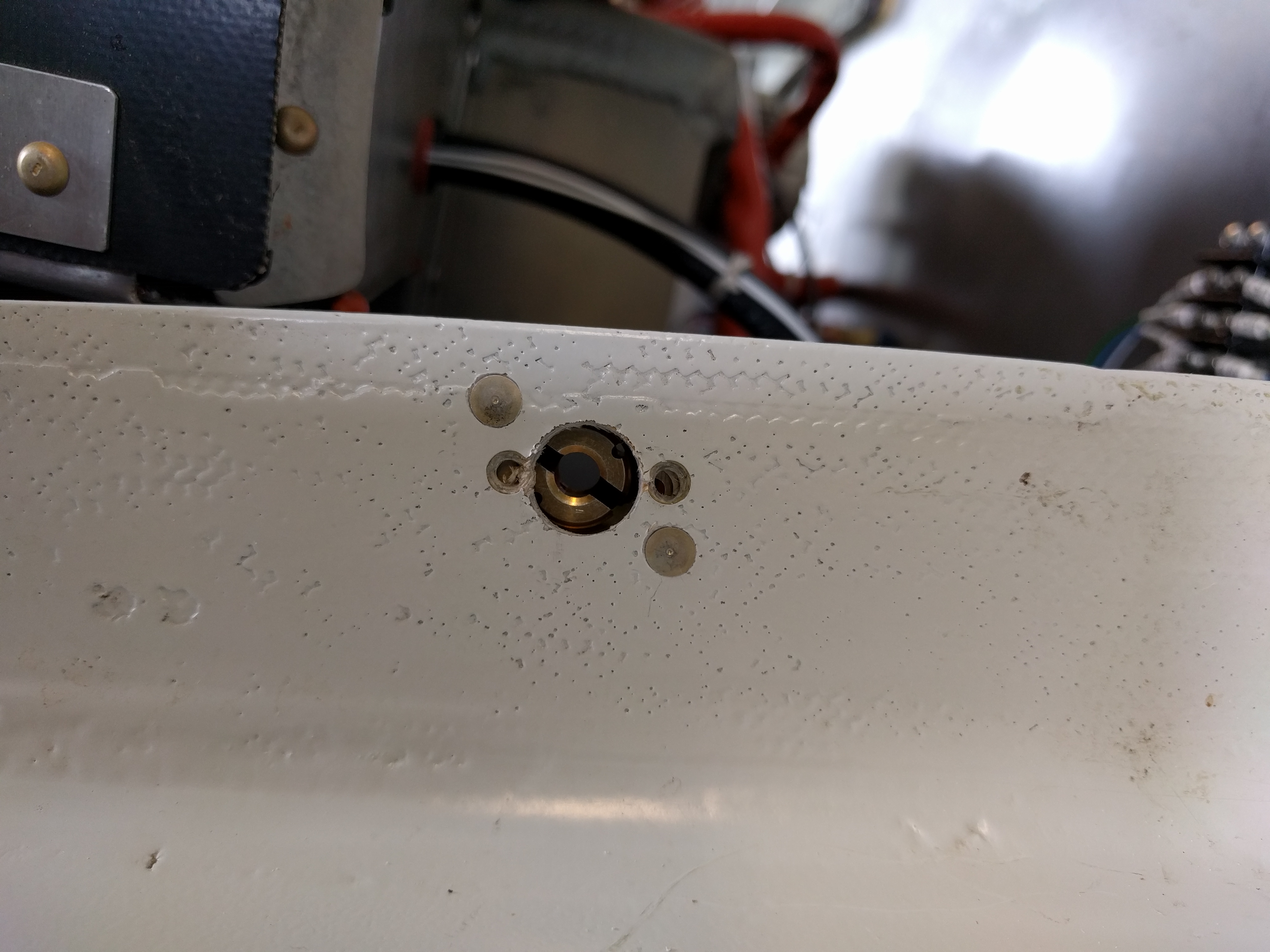
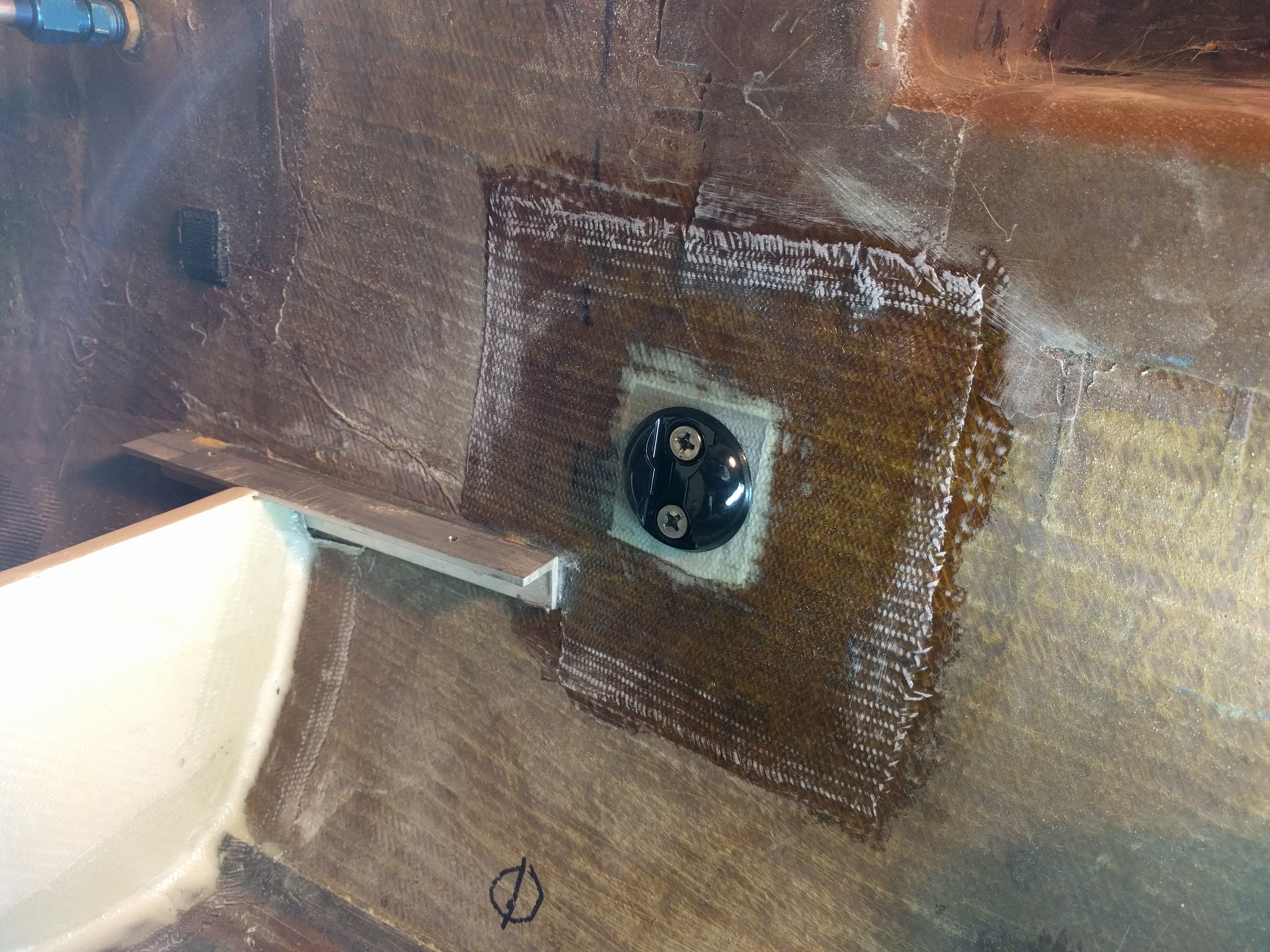
Here is the receptacle.

The small stud on the housing prevents a spring clip from engaging. This allows you to turn the receptacle in or out to adjust it. Once you have it at the correct depth, you remove the stud, rotate the receptacle 90 degrees in or out (whichever is closer) and the clip engages the receptacle locking it in position.
I installed two on the upper cowling just to see how difficult the install would be, how it would look and most importantly, how it would hold up. The installation was too bad, but the results were very nice.


After about 4 hours of flight time, I could see no adverse wear or stress as a result of the two fasteners. So now it’s time to get serious about installing.
The first task was to make a drill guide. It would have been nice if the rivet holes matched the existing nutplates, but with the size of the receptacle housing, that wasn’t going to happen. Skybolt sells a drill guide but I spent my lunch money for the year on their countersink tool. So I grabbed some steel (never make a guide you need to use more than two times out of aluminum) marked, drilled and cut.

I filed down one corner so it would fit close if there was a raised edge. Now, all I have to do is attach this guide to the flange with a #8 screw into the existing nutplate.
If the rivet holes were farther apart, I could mount the receptacle in the same orientation. But because they’re just a little farther apart, that won’t work. I tried rotating the receptacle 90 degrees but in many cases there wasn’t enough room. So I had to settle for rotating it about 40 degrees off of the existing nutplates.
Installation
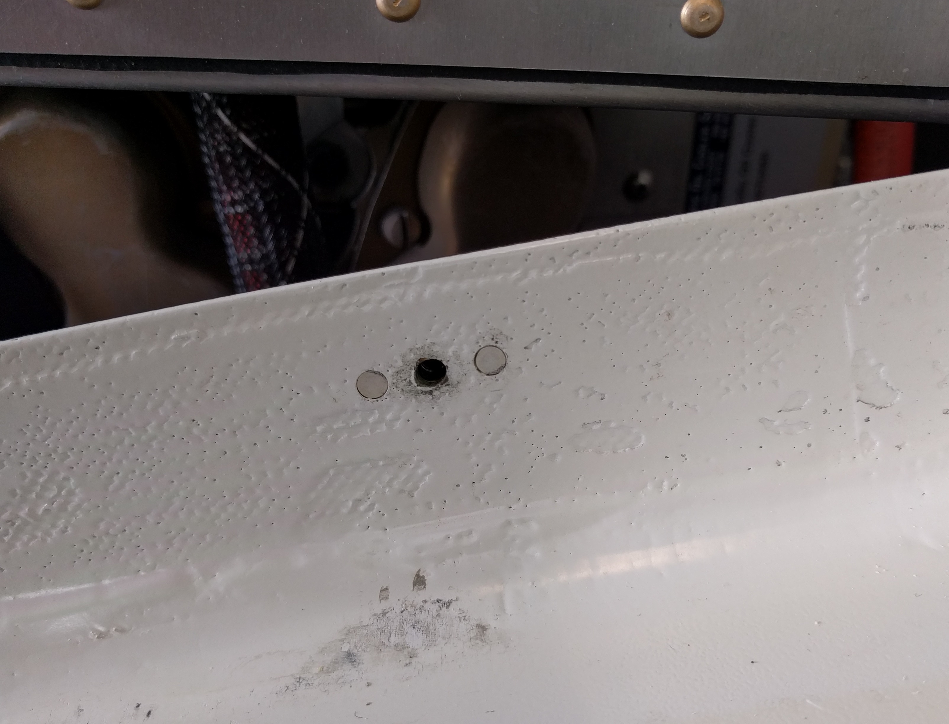
Here’s one of the nutplates on the flange of the wingroot.

After the two #30 mounting holes have been drilled.

Next, remove the old nutplate by drilling out the rivets with a #41 drill bit and enlarge the center hole to 15/32”.

Then countersink for the new rivets and install the receptacle.

I’m not a fan of pop rivets. So whenever possible, I use solid rivets. Pop rivets are used for places that I can’t get the rivet squeezer into.
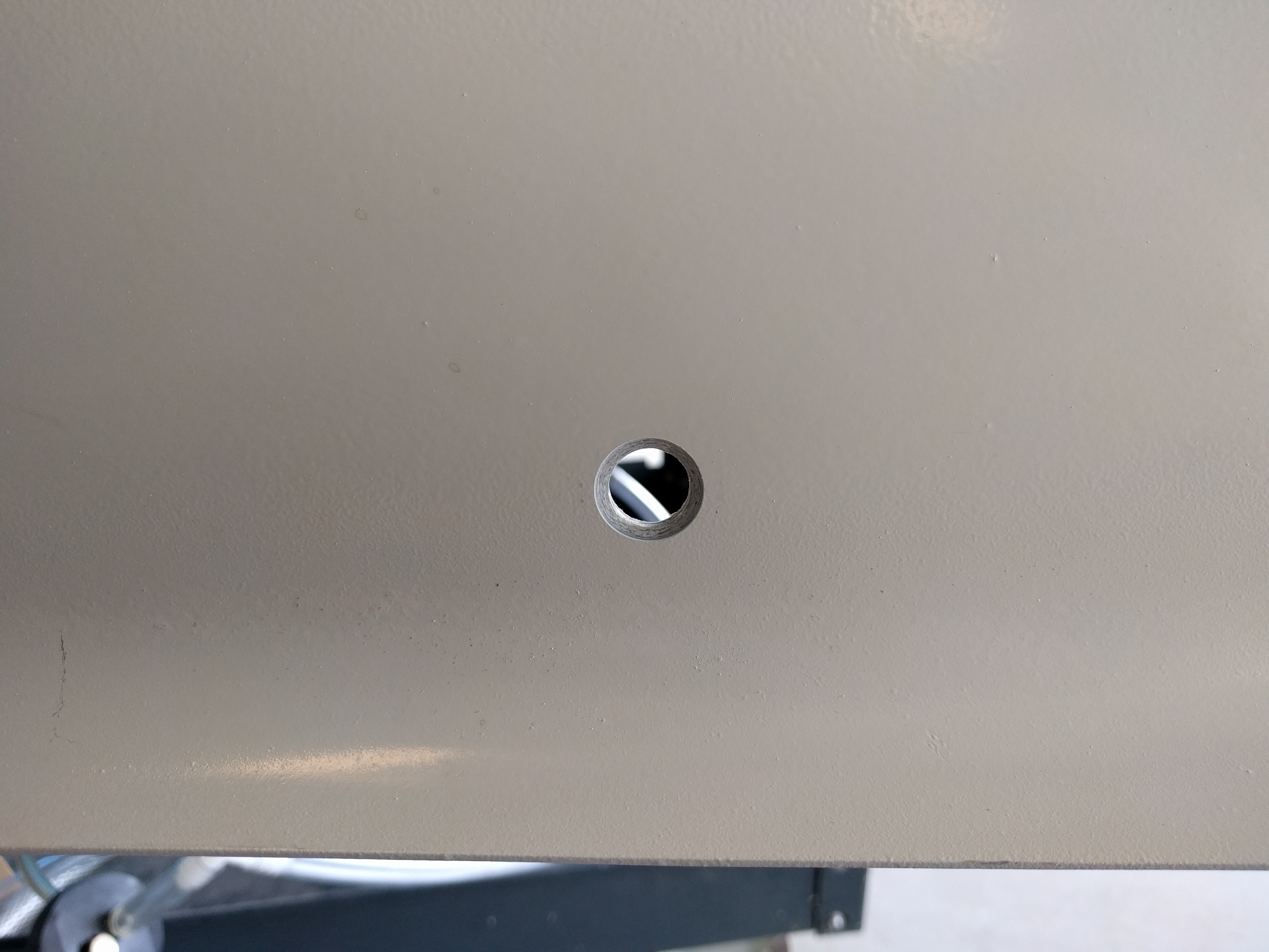
Preparing the outer panel for the fastener.
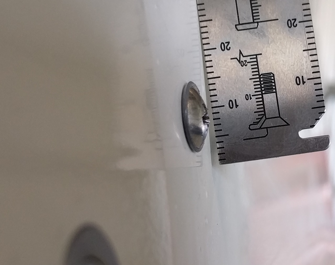
Here is the cowling where the #8 screw was used to attach the cowling. Notice how the screw head/washer has displaced the paint (actually primer since I haven’t painted yet).
Because the new fastener will be in the exact same position as the old screw, it’s a simple matter of enlarging the hole to accommodate the grommet. A step drill gets the opening to within about a 32nd of an inch. Then a 15/32” drill bit finishes the opening.

Finally the incredibly, insanely expensive special tool is used to create the bevel for the grommet.

This is the same type of bit used with the micro-stop countersink tool. But it has a number of different sized guides which attach to the pilot. Once the micro-stop is adjusted, it only takes a second to create the bevel.

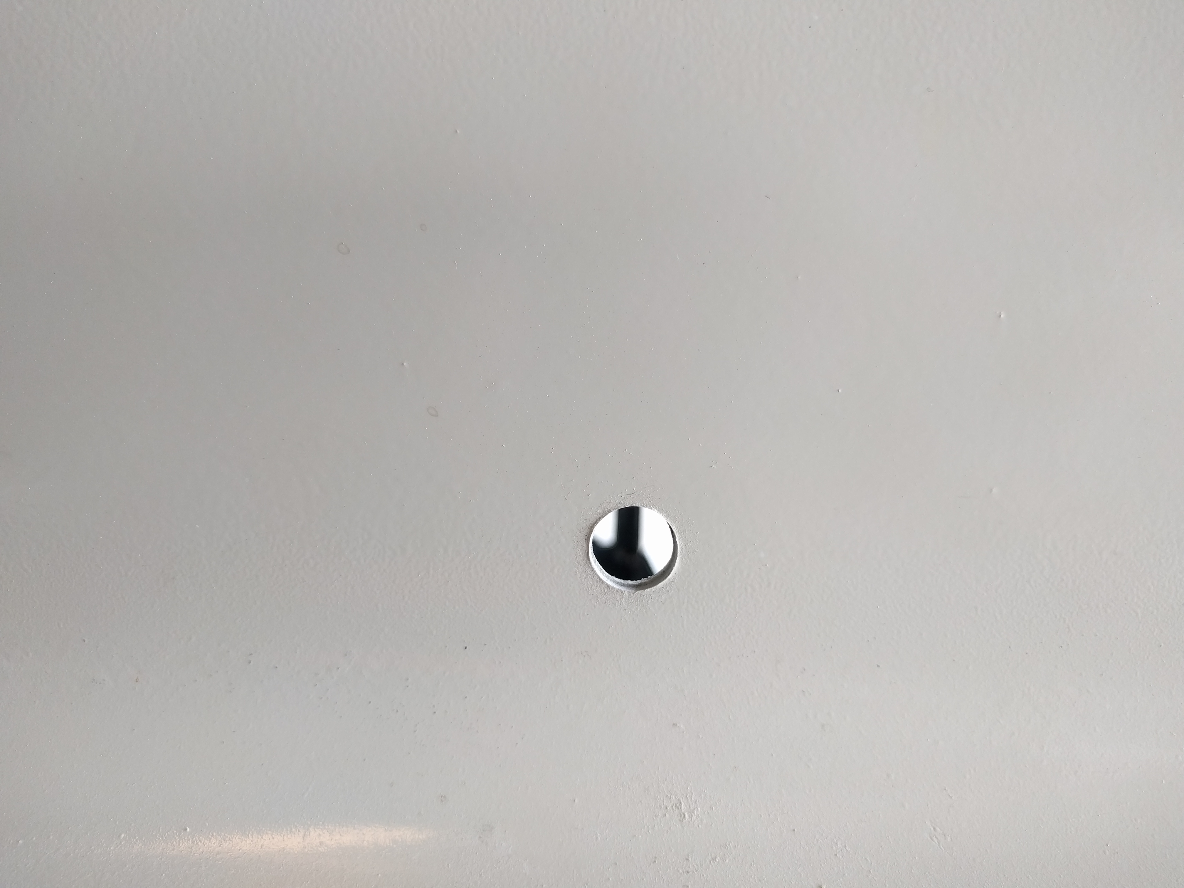
Once that’s done, it’s time to put the cowling on, insert the fastener, and then tighten until the head of the fastener is flush with the grommet. Then remove the fastener without rotating the receptacle. This is accomplished by pushing in firmly while releasing the fastener. Remove the cowling and then remove the stud. Insert a flat blade screwdriver into the receptacle and turn in or out a quarter turn to let the spring clip latch into the receptacle. That’s it.

Repeat about 40 times and you’re done.
I think that when the engine comes out for overhaul, I’ll retrofit piano hinges on the wing roots and upper/lower cowl joint. But until then, this solution will work nicely.
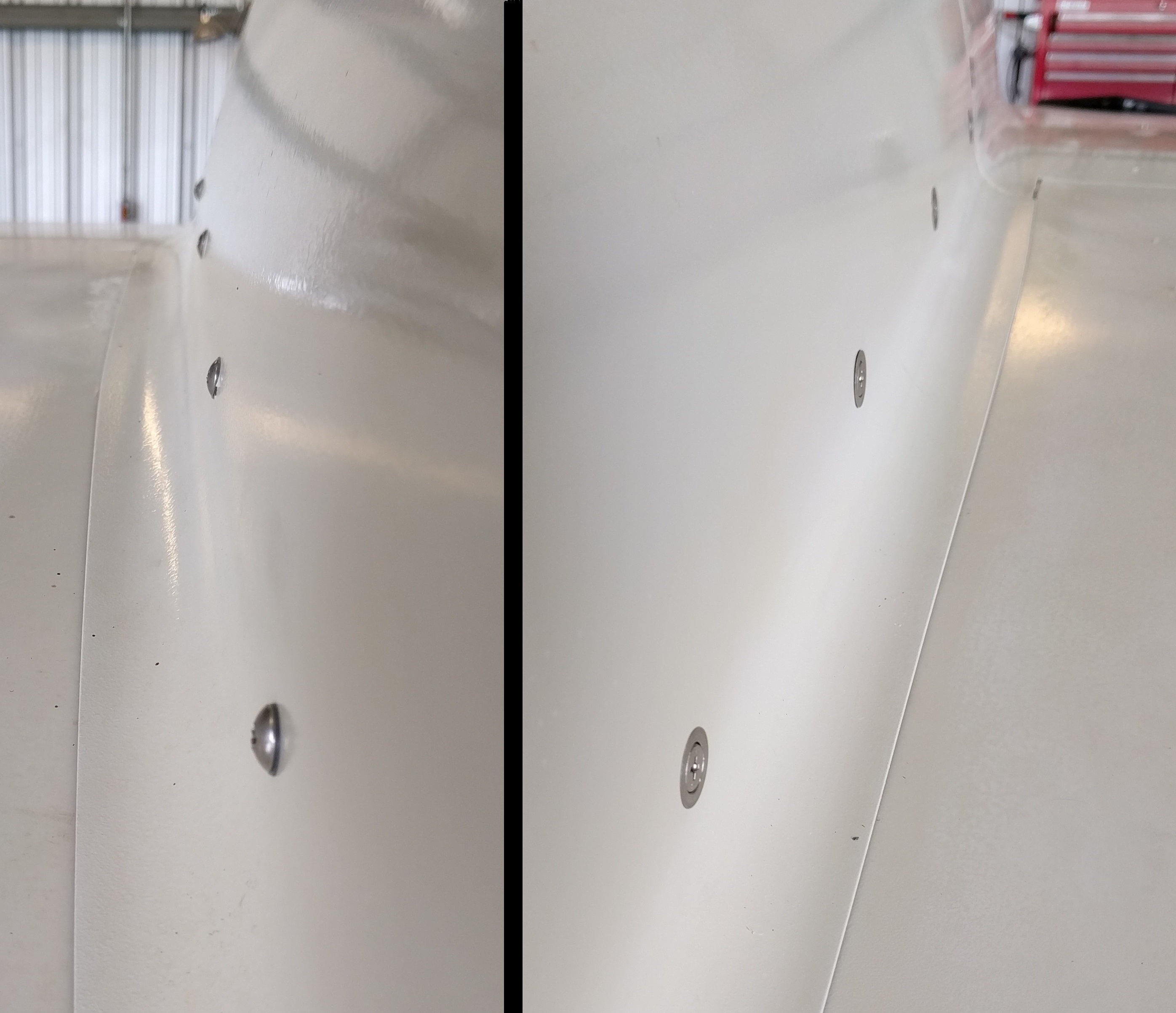
Here’s a split screen view of the left and right side.

Parts:
SK245A161A – Receptacle $4.20
SK40S5-3S – Fastener $3.29
SK-GS – Grommet $1.99
MS20426AD4-5835 Solid Rivets
Tools:
#30 drill bit
#41 drill bit (to drill out old nutplates)
Step drill bit
15/32” drill bit
Rivet Squeezer
Counter sink for 3/32” hole
SKC4S (Counter sink for grommet)
Drill
#2 Phillips Head Screwdriver
Large Flat Blade Screwdriver