3.4.5 – Elevator Hinge Installation

This entry is part 1 of 3 in the series 03 - Canard / Elevator

Next I mounted the four hinges to the two elevators. The elevators are mounted at the rear of the canard. When the control stick is pulled back, the elevators are deflected down which increases lift at the canard (airplane goes up).

Two holes are drilled in the hinge. Then structural epoxy is applied to the hinge and it’s riveted to the elevator. Finally, another hole is drilled between the two rivets and a screw and nut are used to further hold it in place.

This is the area of the elevator that the hinge gets attached to.  I’ve already sanded the primer and filler away from the carbon fiber and drilled the holes for the rivets.

2008-01-16 1010 IMG_5739

This is one of the hinge brackets riveted, glued and screwed in place.

Here are both elevators with the four hinge brackets on each elevator.

3.4.6 Elevator Hinge Arm Installation

This entry is part 2 of 3 in the series 03 - Canard / Elevator

Now it’s time to mount the hinge arm to the canard.

First, the location of the L-shaped hinge arms are identified and slots are cut into the fiberglass at the rear of the canard. Then the foam is removed to create a pocket for the hinge arm.

Next the position of the elevator (relative to the canard) has to be established. This is done by laying the canard on its back and using straight beams to establish the bottom of the canard. Then the elevators are put into position and clamped in place with the hinge arms in their pockets. To insure alignment of the two elevators, the elevator torque tube is temporarily installed which connects the two elevators.

Here’s the canard (it’s upside down so you’re looking at the bottom) with the two elevators in position. The elevators are held in the approximate position with aluminum I-beams, weights and clamps while we tweak the alignment. Lots of straight edges and string is used to make certain everything is aligned.

 2008-01-18 1354 IMG_5787 2008-01-18 1354 IMG_5788 2008-01-18 1355 IMG_5789

Once we’re happy that everything is just right, an epoxy/cabo mix is injected into the pockets where the hinge arm are.

2008-01-22 1737 IMG_58452008-01-22 1737 IMG_5846


3.5.2 Elevator Torque Tube Install

This entry is part 3 of 3 in the series 03 - Canard / Elevator

Okay, so there’s a small wing on the front. This is the canard. On the trailing edge of the canard is a moveable surface. This is called the elevator. By changing the position of the elevator, the amount of lift that the canard creates can be changed.

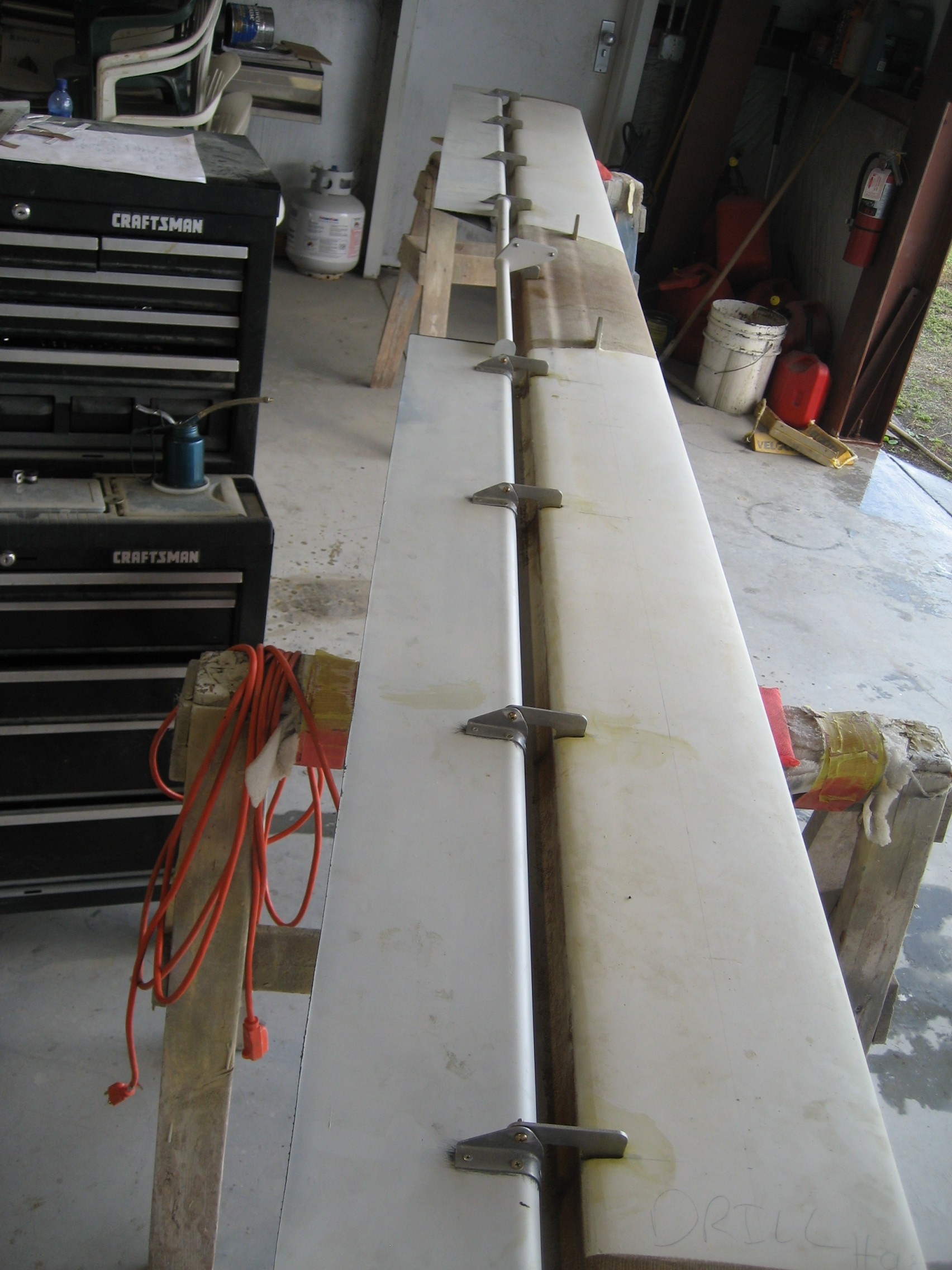
Here’s a picture of the canard and elevator from January when I was installing the hinges.

2008-01-22 0803 IMG_5838

In this picture, the elevator is upside down. So this is looking at the bottom. On the right is the canard. On the left you can see the two elevators (left one on the bottom of the picture, right one on the top). The two elevators will move as one. They are connected with the white tubing in between (called the elevator torque tube). At the time this picture was taken, the torque tube is not attached to the elevator. That’s what I need to do next.

The elevators pivot point is not at the leading edge of the elevator.  It’s actually about 1-1/2″ below the center of the elevator. This makes the elevator a type of “Fowler Flap” where the moveable surface moves down and aft. The torque tube itself is aligned with the pivot point of the elevator and has an arm with ties in to the leading edge of the elevator.

If the attachment at the elevator is not exactly positioned, the torque tube will move up/down/forward/aft as it rotates.  The problem with that is it makes it difficult to seal where it enters the fuselage and could also bind. So to locate the correct position, I decided to use my handy laser again. The problem is that the “tab” on the end is not perfectly aligned with the tube so I can’t just align everything to the center of the tab. I need it aligned to the center of the torque tube. So here’s what I did: I made a jig to allow me to rotate the torque tube so I could mark the exact center of the tube on the tab.

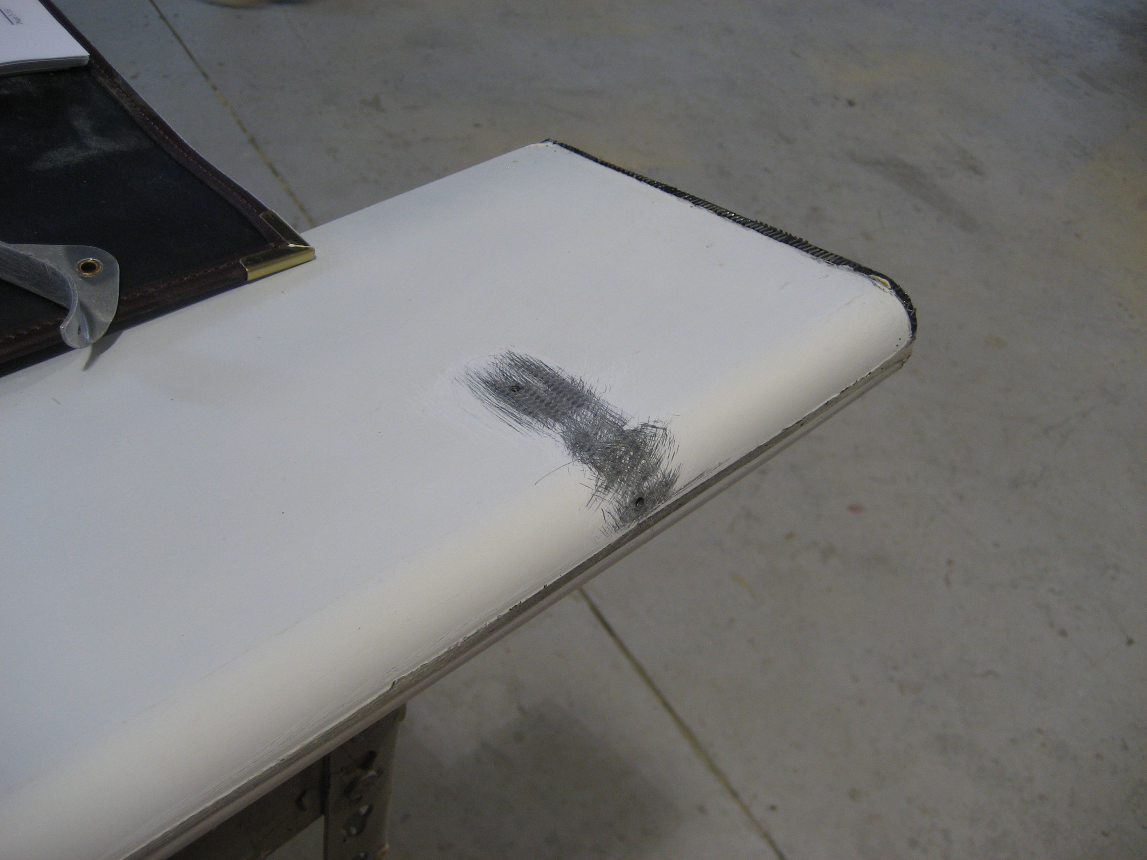
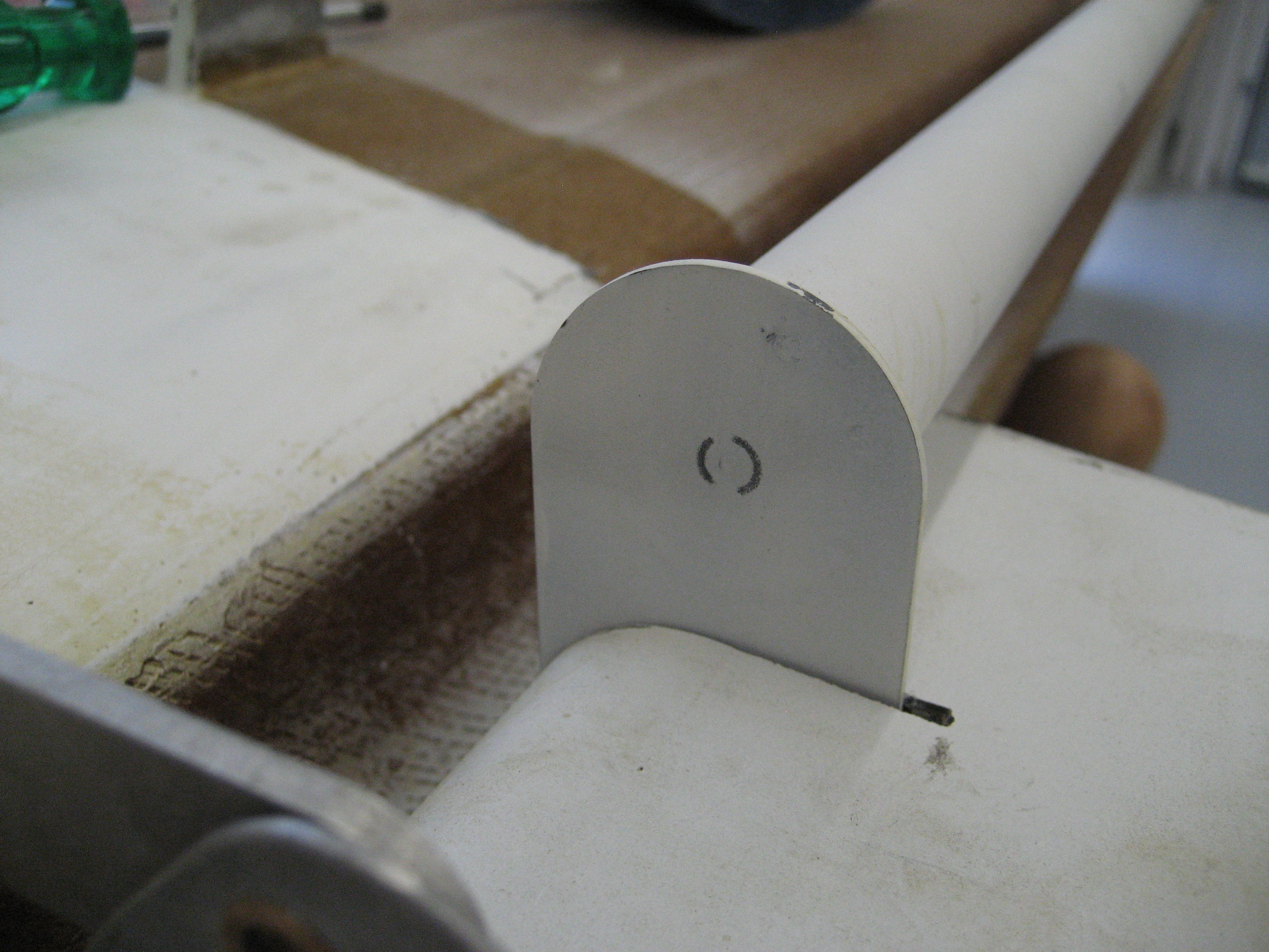
Here’s the torque tube end with the marks identifying the center. The jig wouldn’t let me make a complete circle, but I was able to adequately mark the center

  2008-07-03 1156 IMG_7188

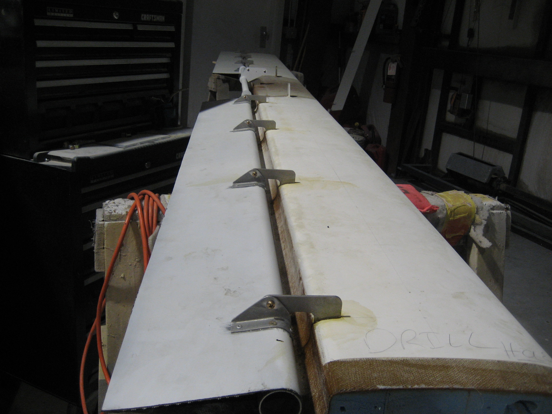
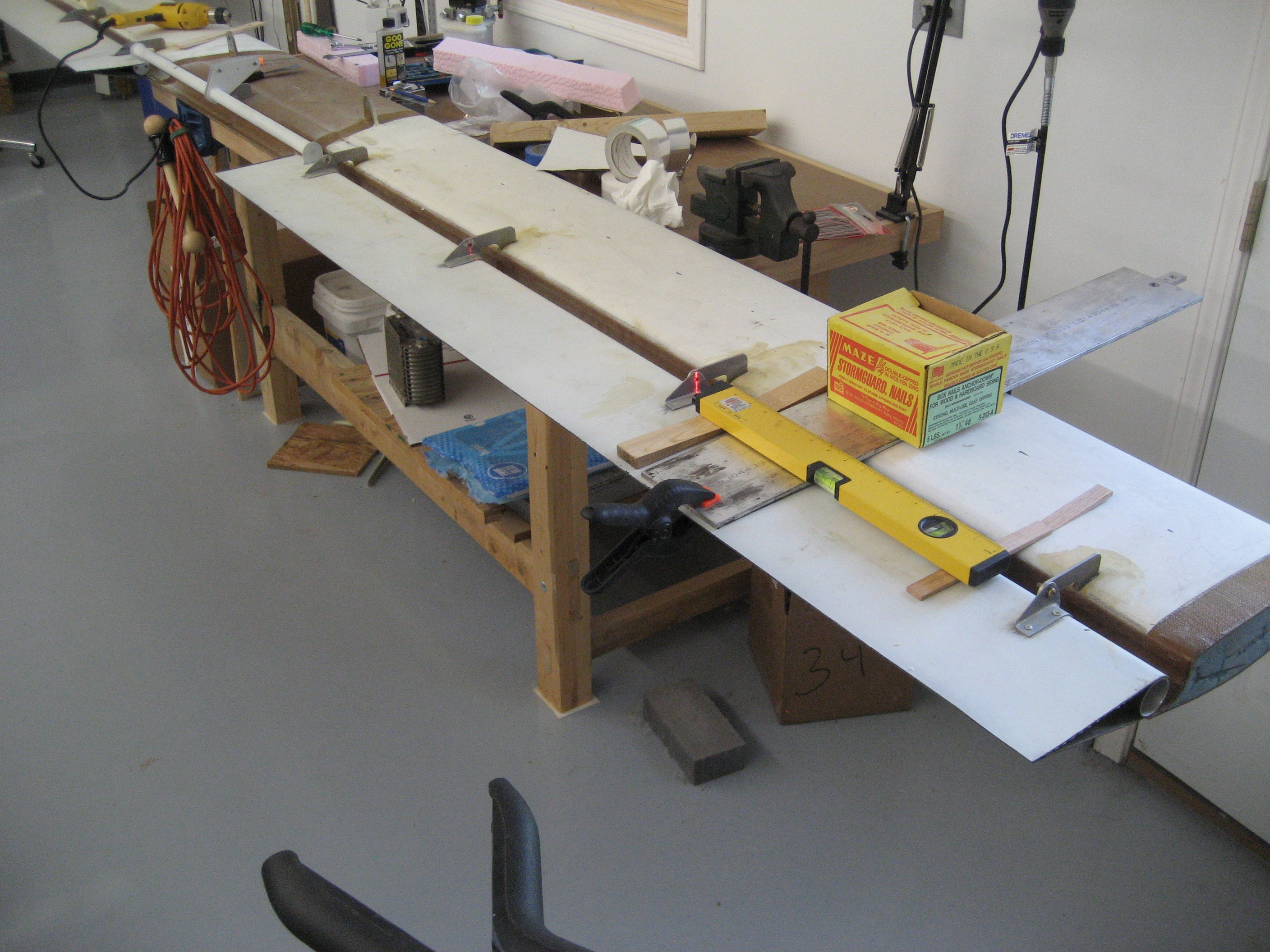
Then I mounted the elevators and torque tubes on the canard. I left the three inboard hinge screws out. I put the laser so that it would shine through the holes on the three hinges without screws.

My setup with the laser.

  2008-07-05 0604 IMG_7194

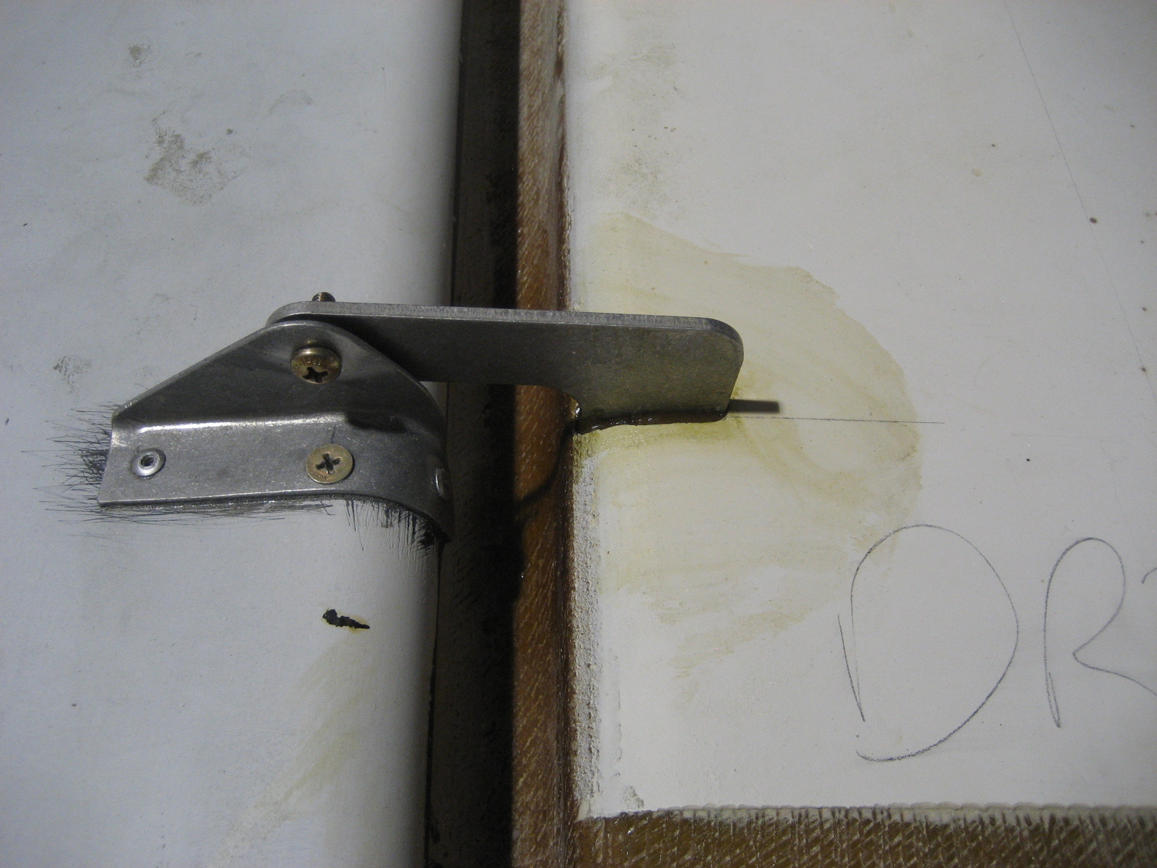
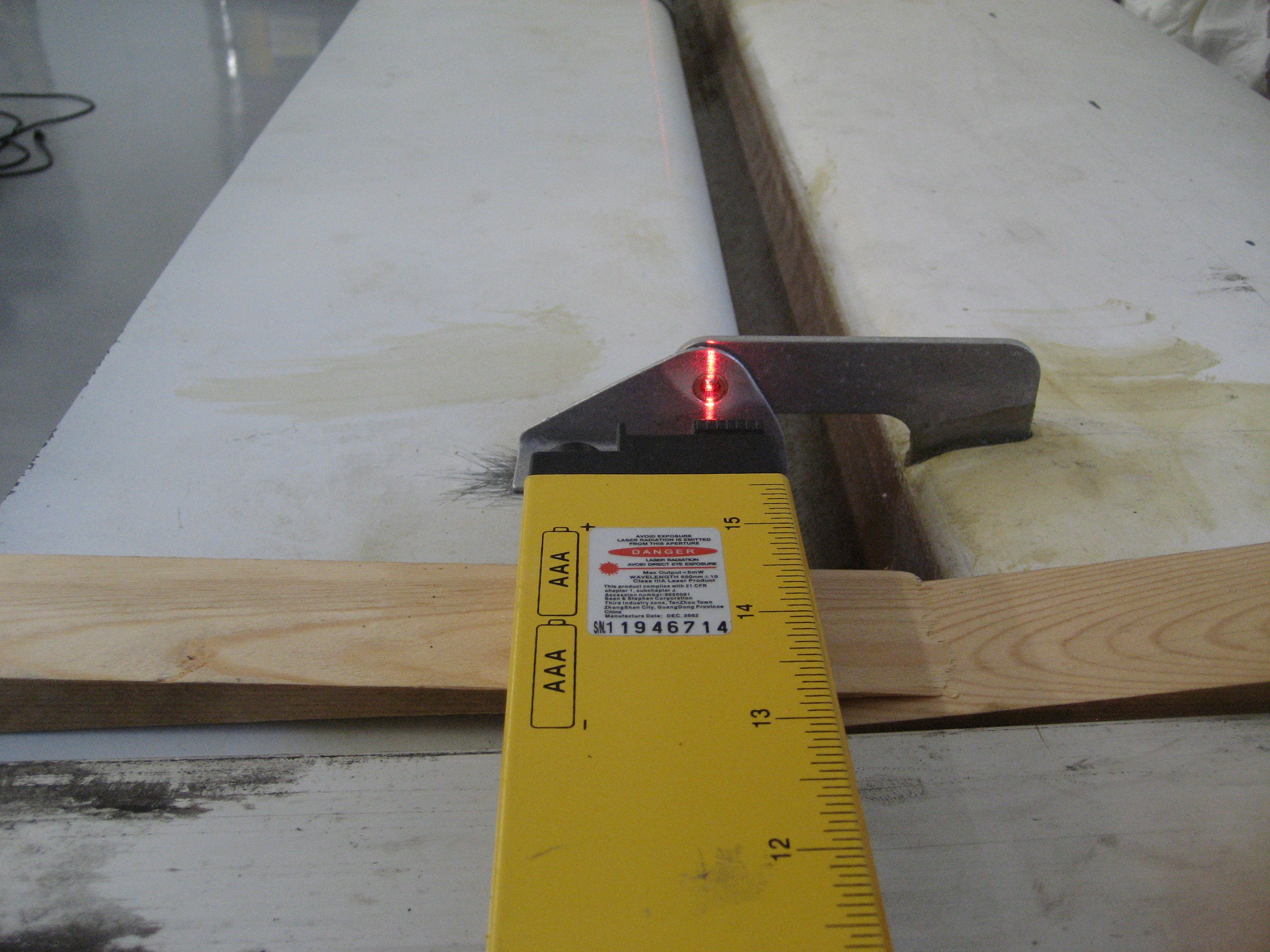
Here’s the laser shooting through the first hinge.

  2008-07-05 0605 IMG_7196

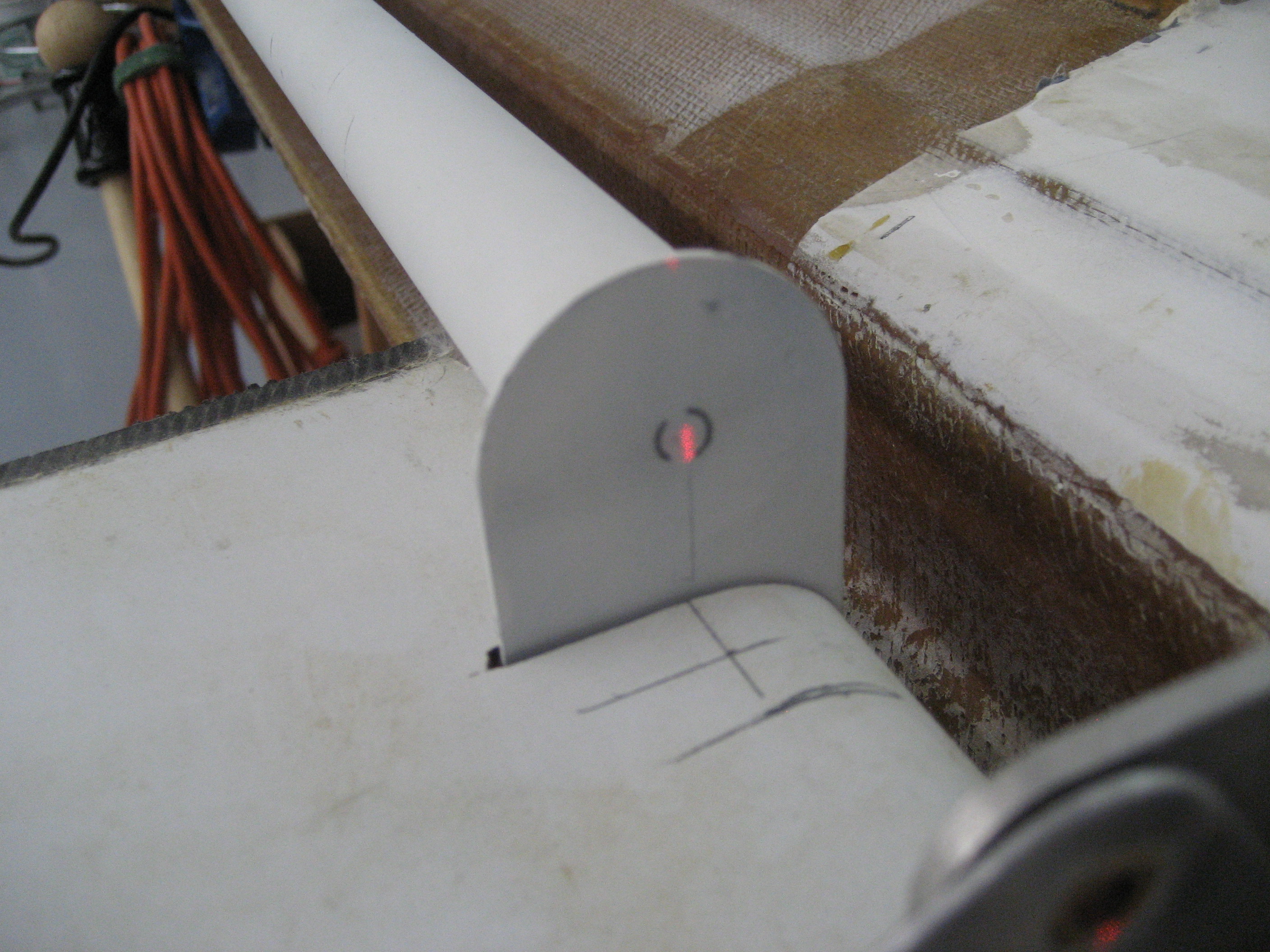
A little more to the right will have it dead-solid-perfect.

 2008-07-05 0605 IMG_7197

Once it’s in position, I drilled through the elevator and torque tube. Then put in the screw and nut.