
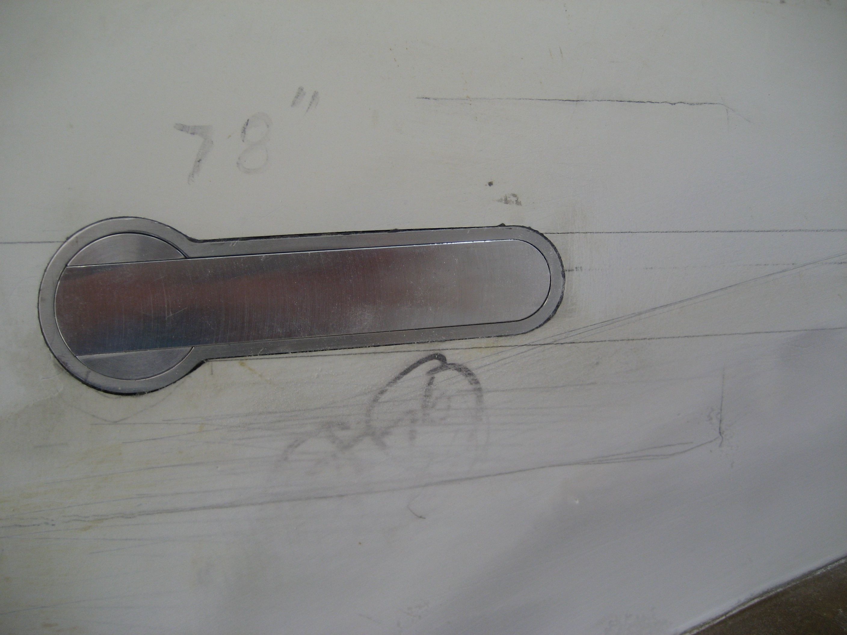
One of the things about the stock Velocity kit that I really don’t like is the door handle. Some people call them “Toilet flush” handles. Here’s why:
That’s how you open the door from the outside.
The inside isn’t much better.
Closed
Open
After poking around on the internet, I found some door handles designed for experimental aircraft.

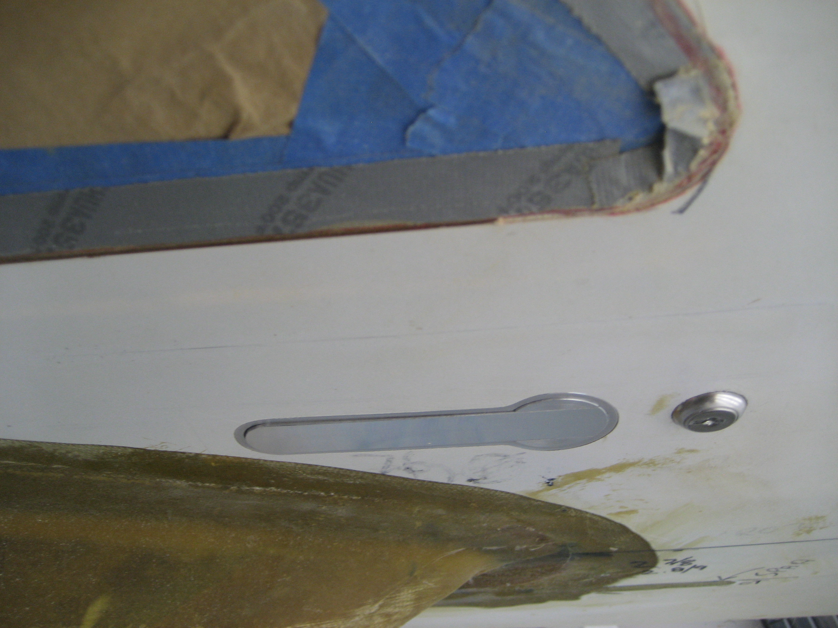
Not only is it flush mounted, but it includes a lock. The handle is spring loaded and pops out to operate.
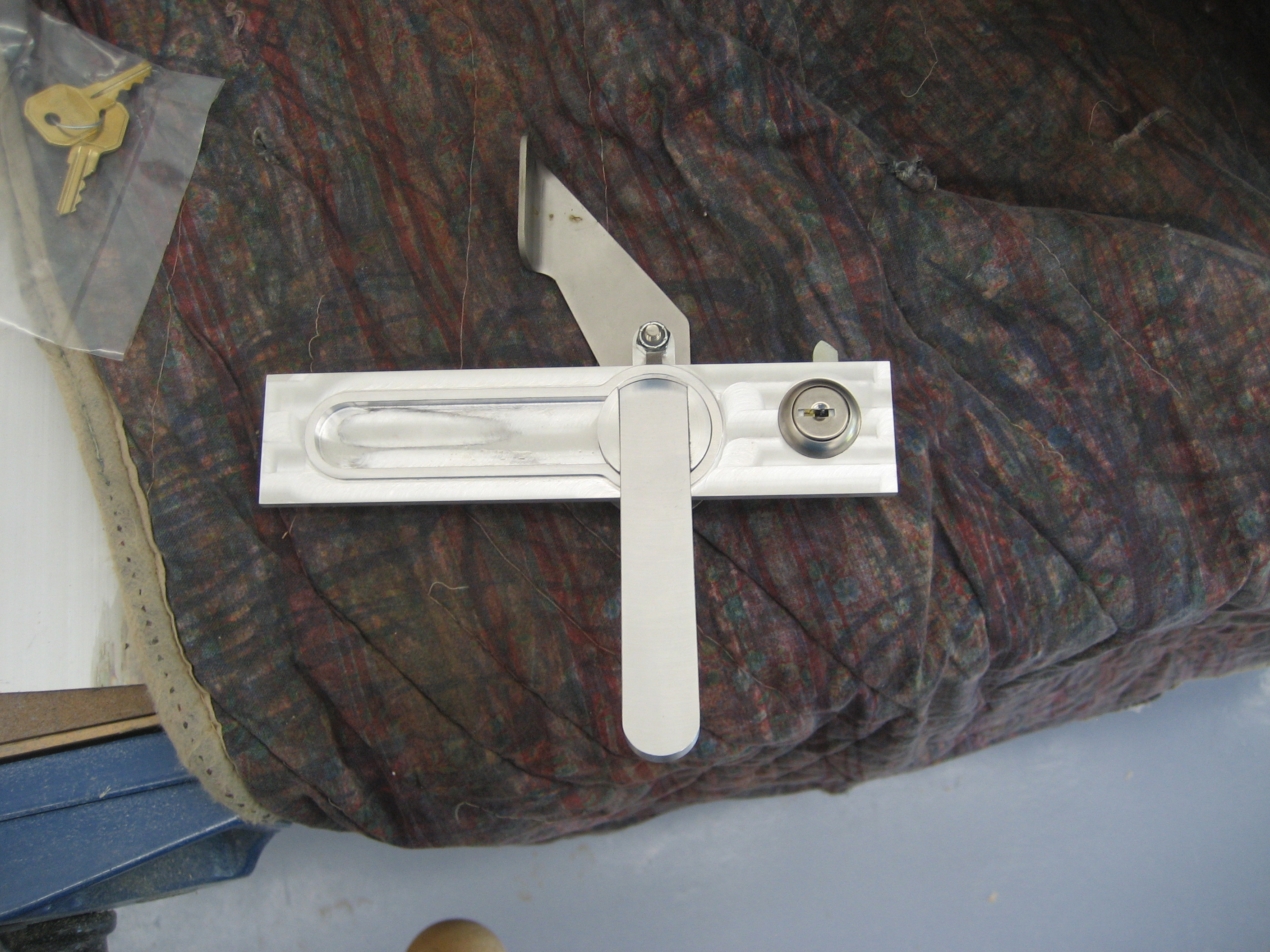
Installing this is going to be easy compared to making it work with the four pins. The person that designed the handle made it for a Van’s RV airplane. They only have two pins (one going forward and the other going towards the rear). In this inside view you can see the center pivot screw and the forward and rear screws that the two links connect to.

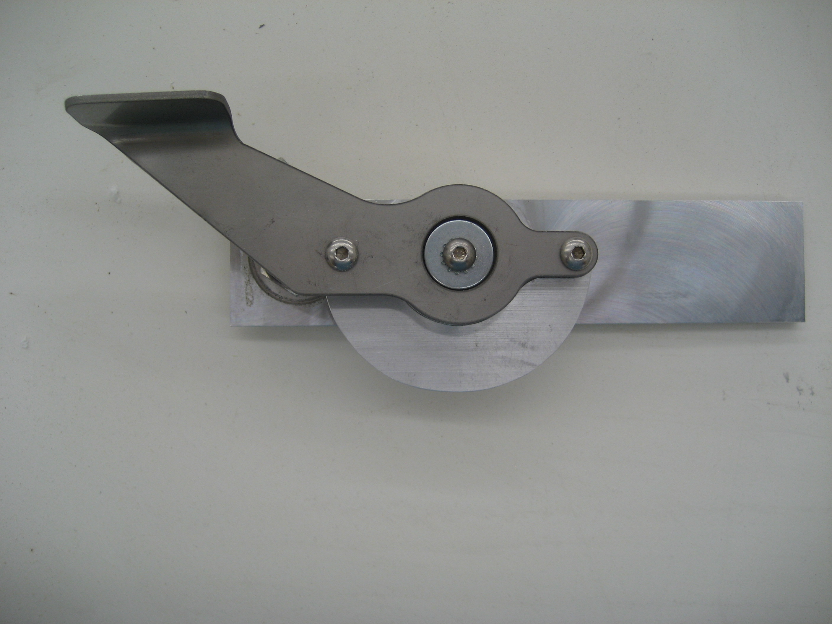
With the interior handle removed, you can see the hub (or what the manufacture call the “driver plate”.

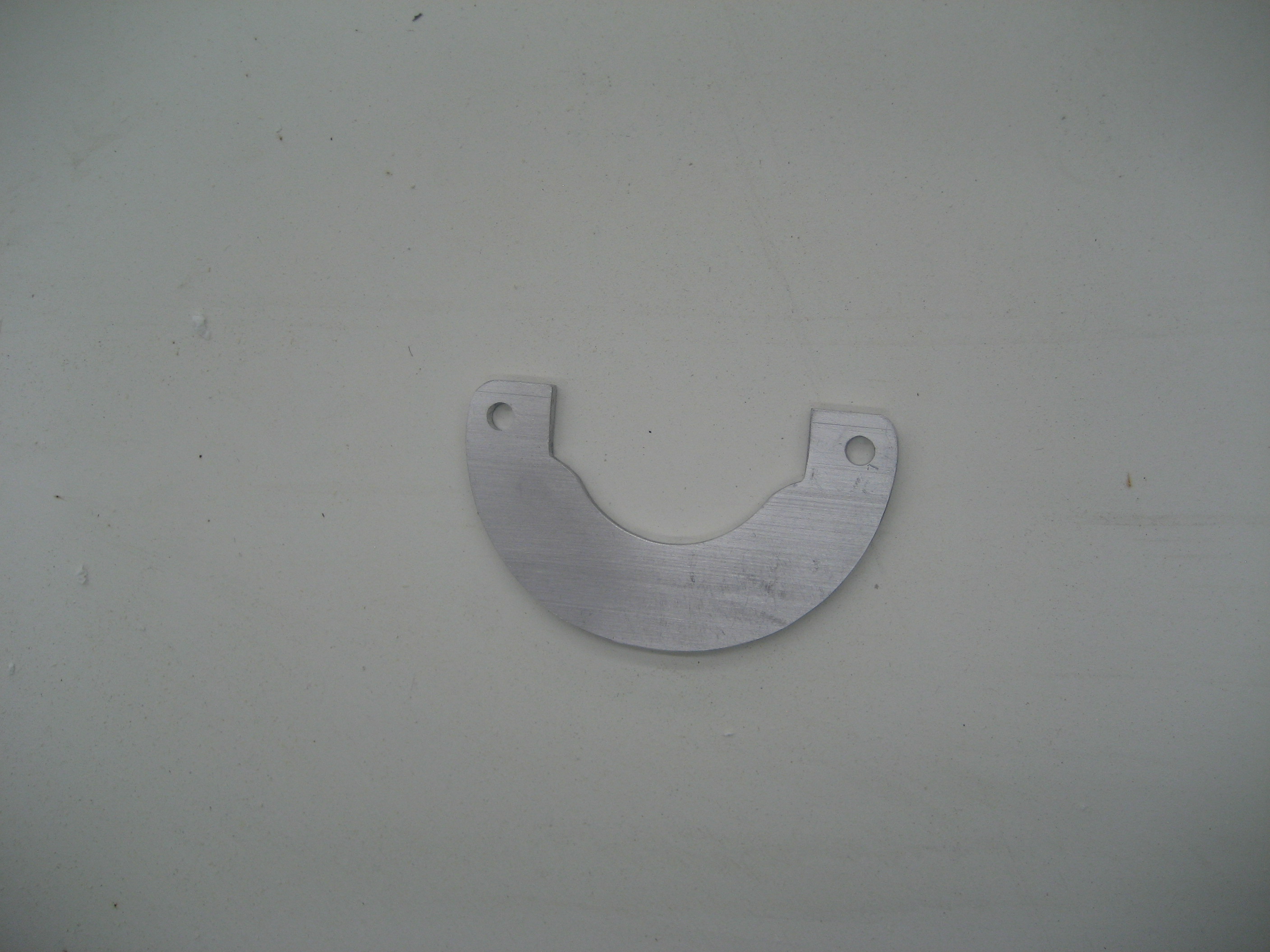
So how do you connect four links to a handle designed for two? Improvise!
The Velocity door has an upper front and rear pin like the RV’s. Which means I only needed to accommodate the two lower pins. So I made a “Cam Plate” that would tie in to the existing hub. In this picture, I haven’t drilled the two holes for the lower pins yet.
Here it is on the hub.
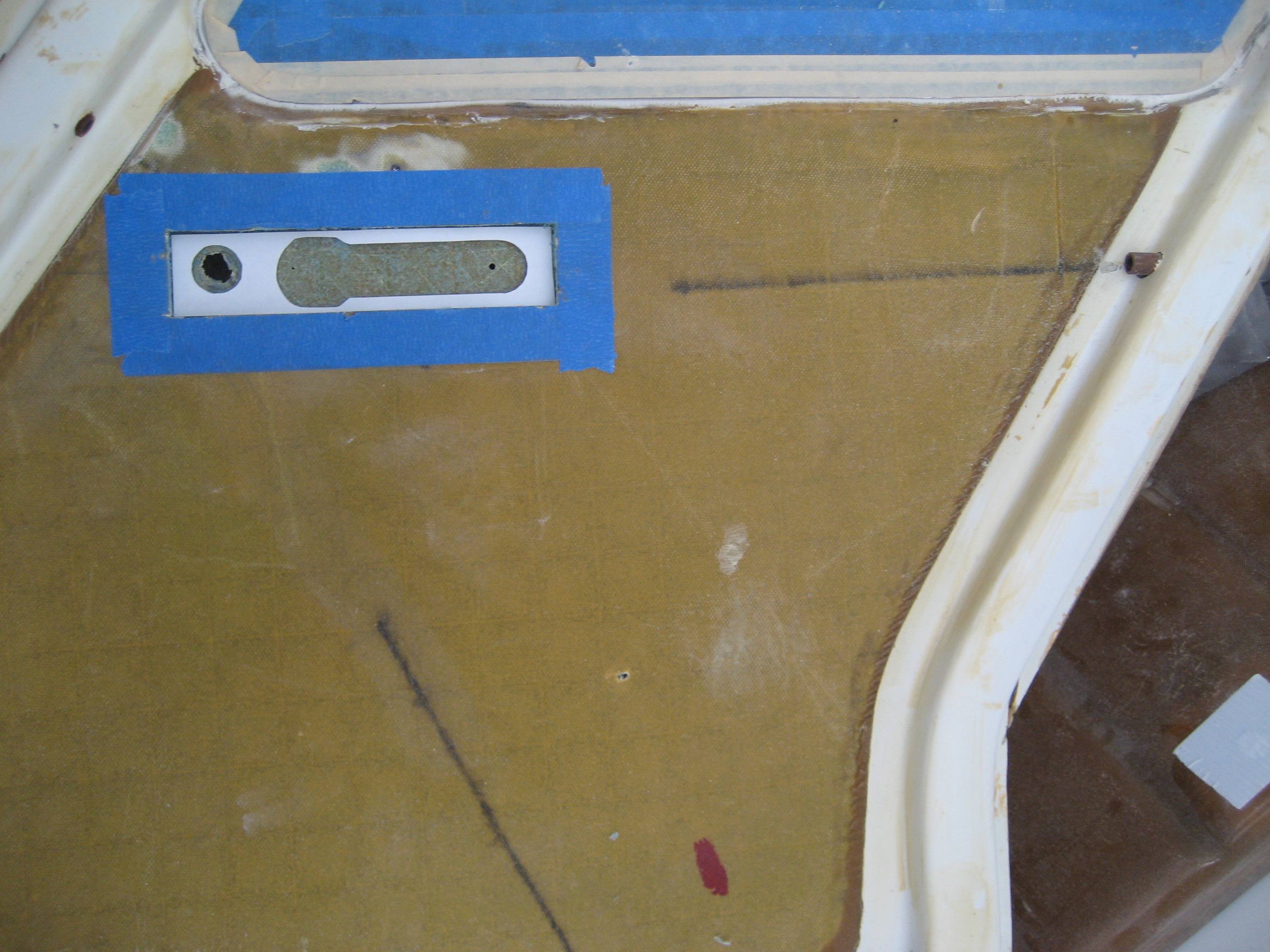
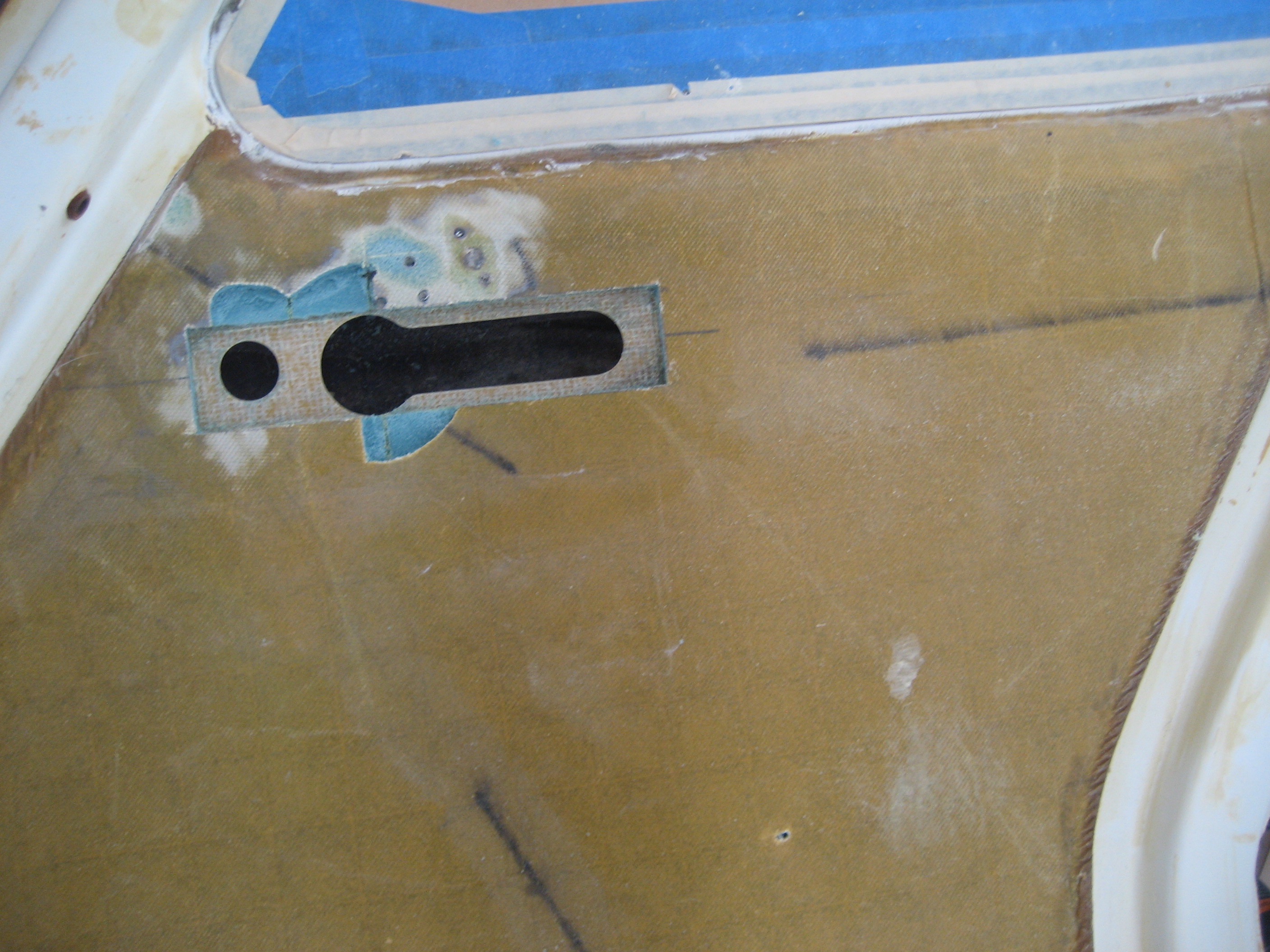
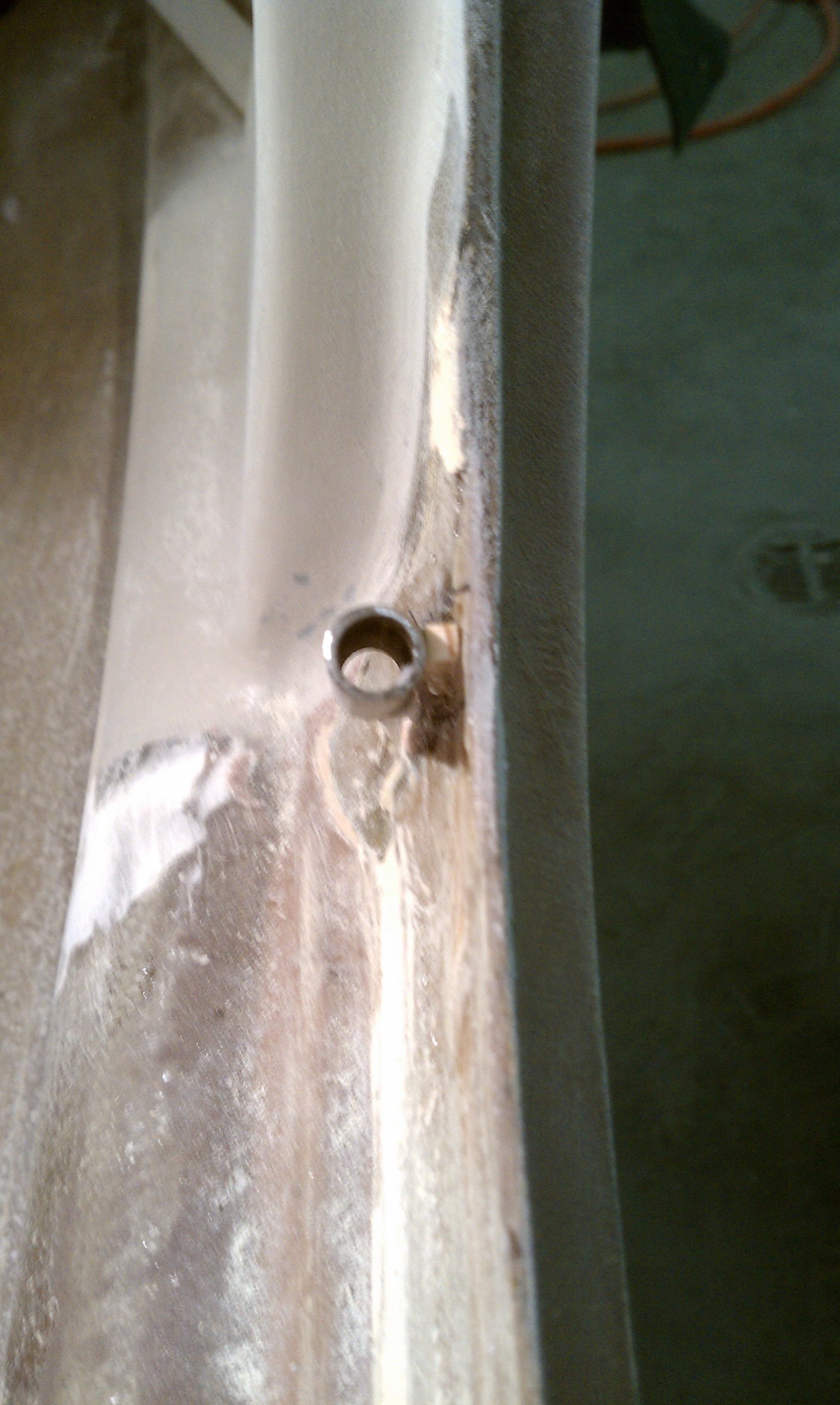
Once I was certain that I could design the interface between the handle and the pins, I was ready to install it in the door. First, I decided that I would use the hole for the existing handle for the lock of the new handle. Then I drew a level line on the outside of the door centered on that hole. I drilled a pair of holes on that line so I would know where the centerline was on the inside. Then I marked where the handle assembly would be and where the hub would be.

Using Malcolm’s trick, I further identified the line with masking tape.

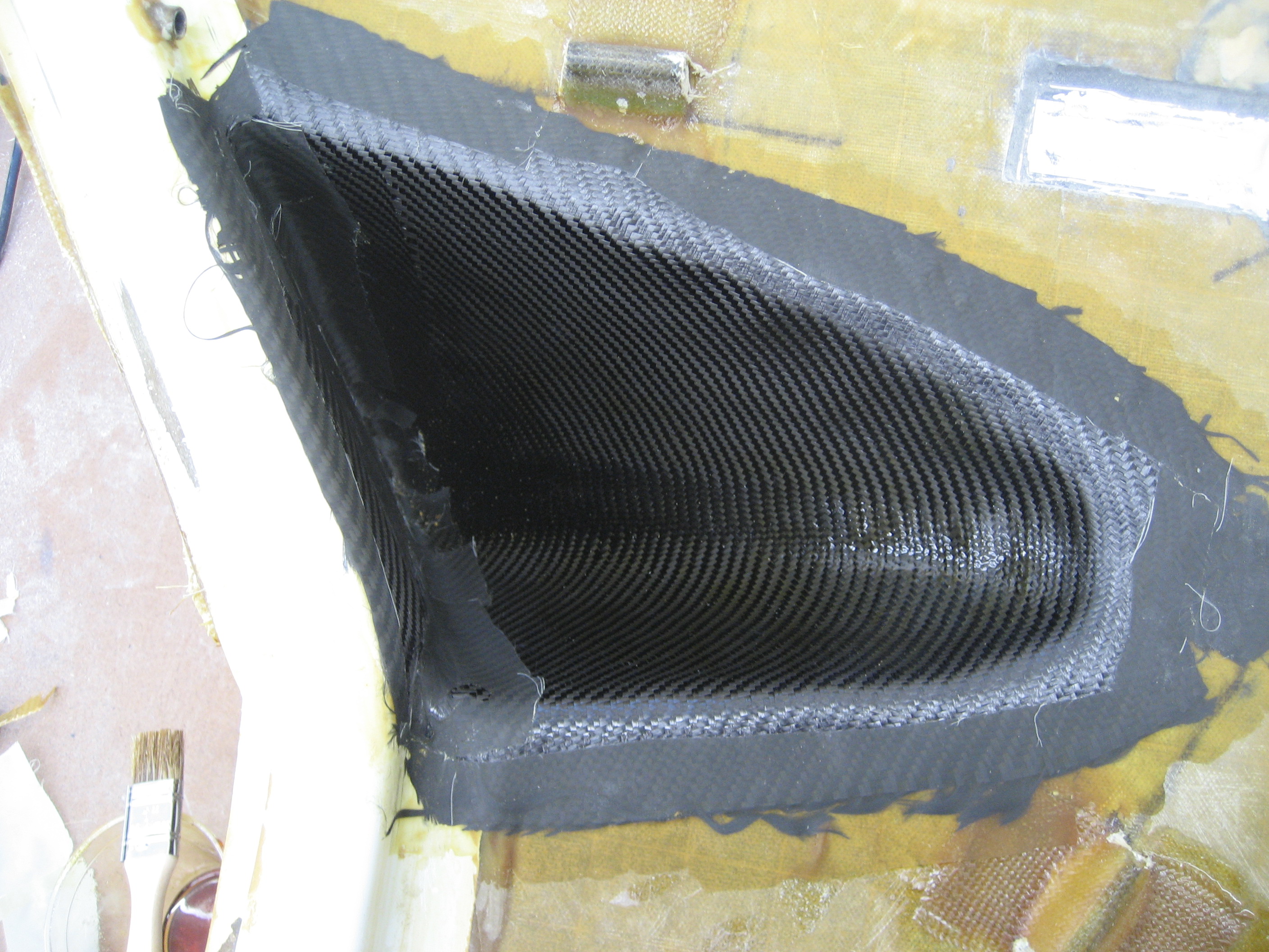
Then I cut the inner skin and removed the foam leaving only the outer skin.

Next I cut a template so I would know where the cut the outer skin.
And marked the outer skin.

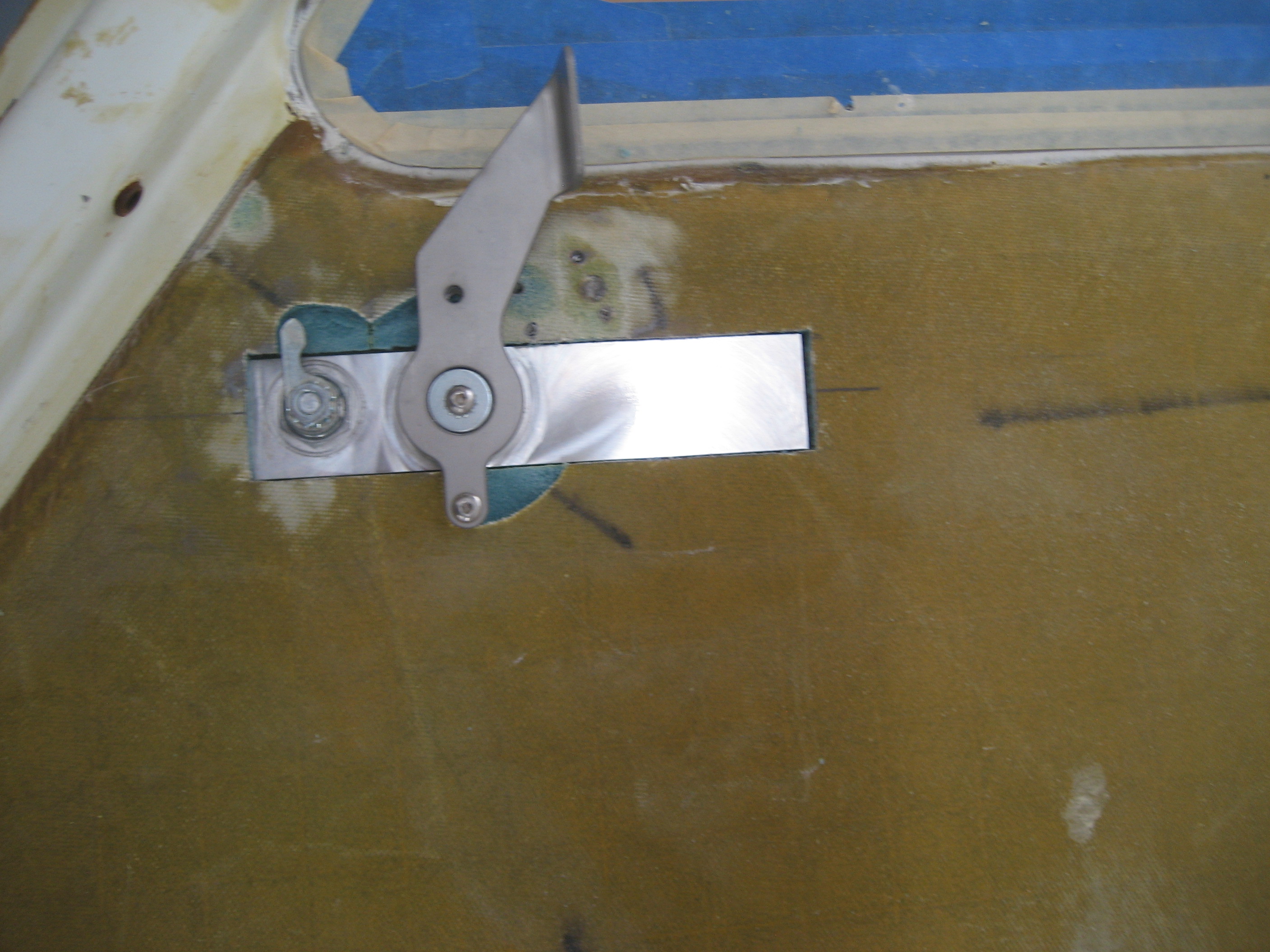
And cut the opening.
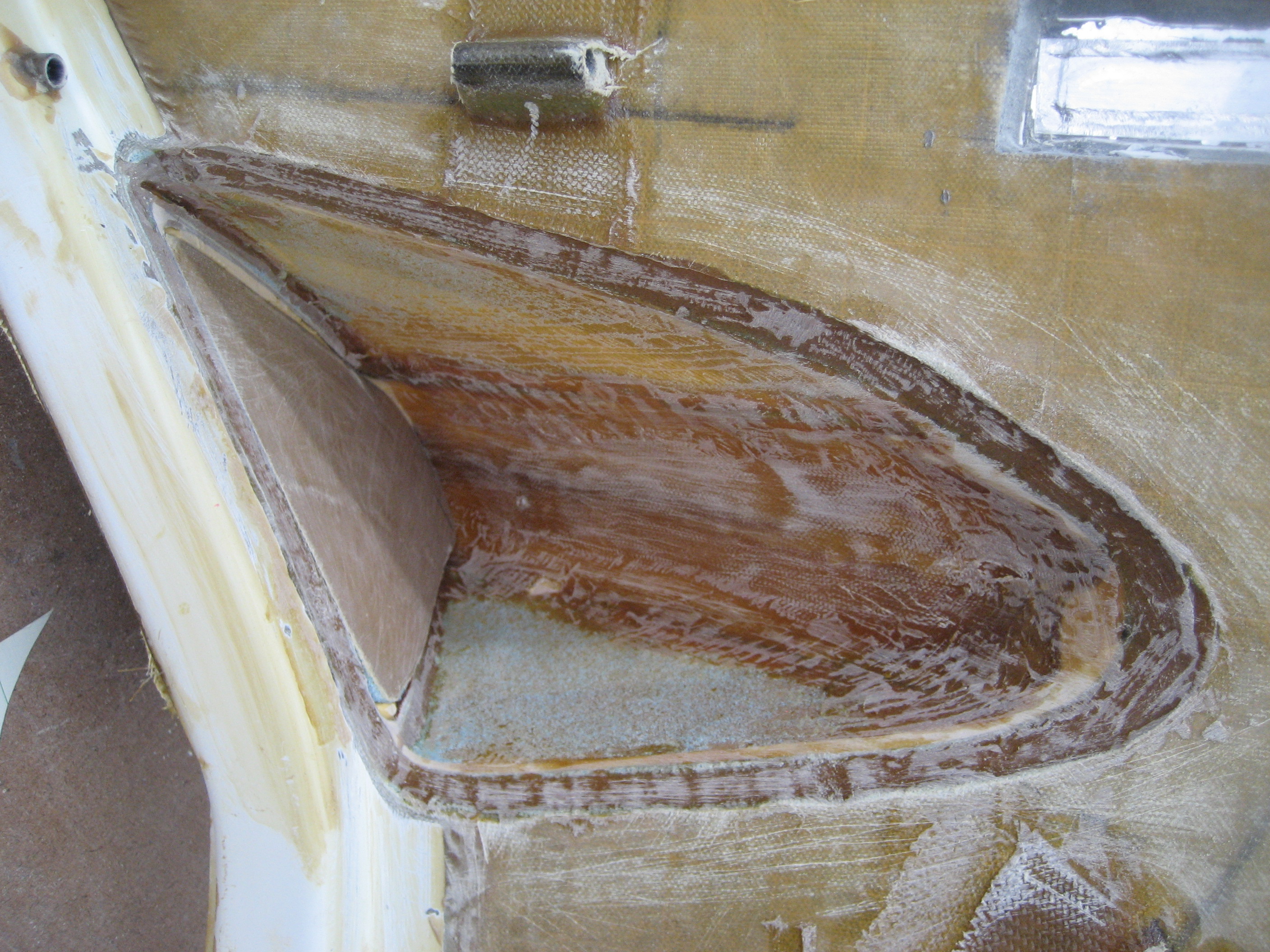
I had to recess the inner skin and foam to allow for the movement of the handle and lock.
Handle in place (closed).

Handle in place (open)
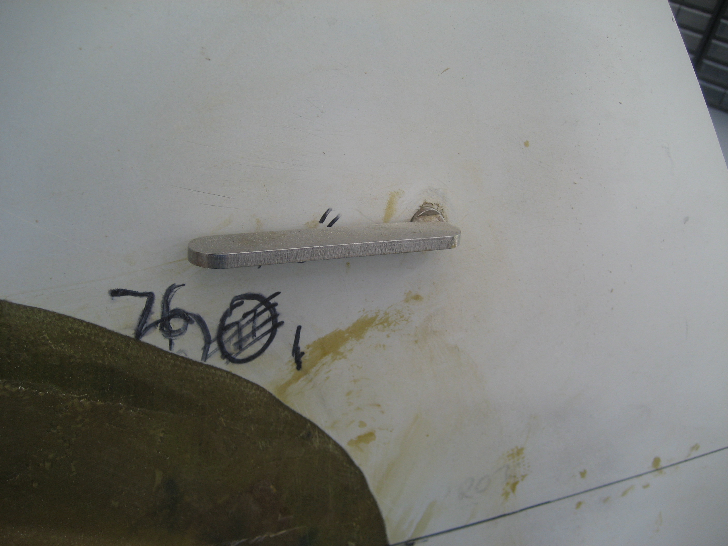
From the outside

Besides the appearance, another bad thing about the handle is that it’s HARD to operate. Once I looked at it I discovered why.
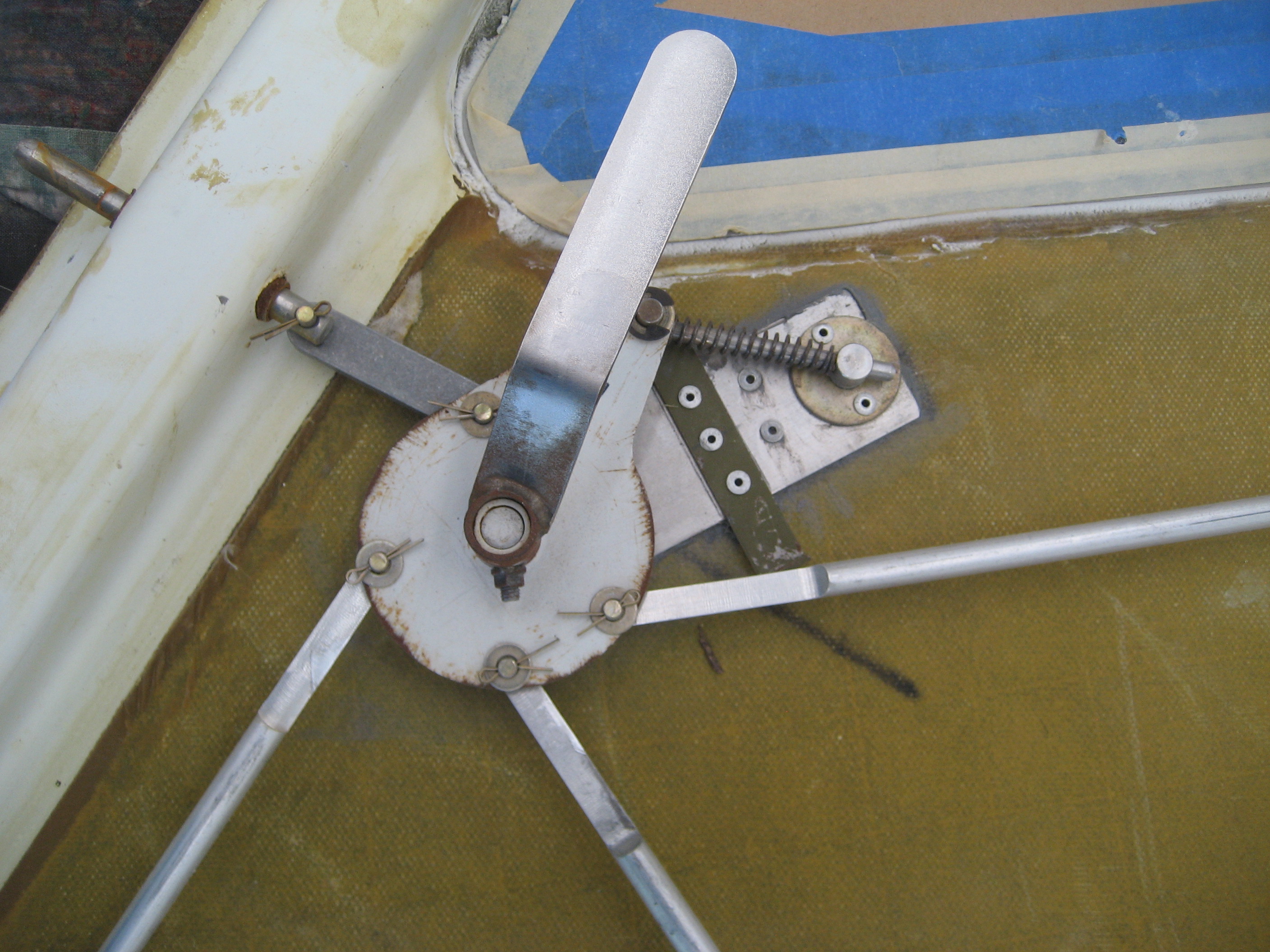
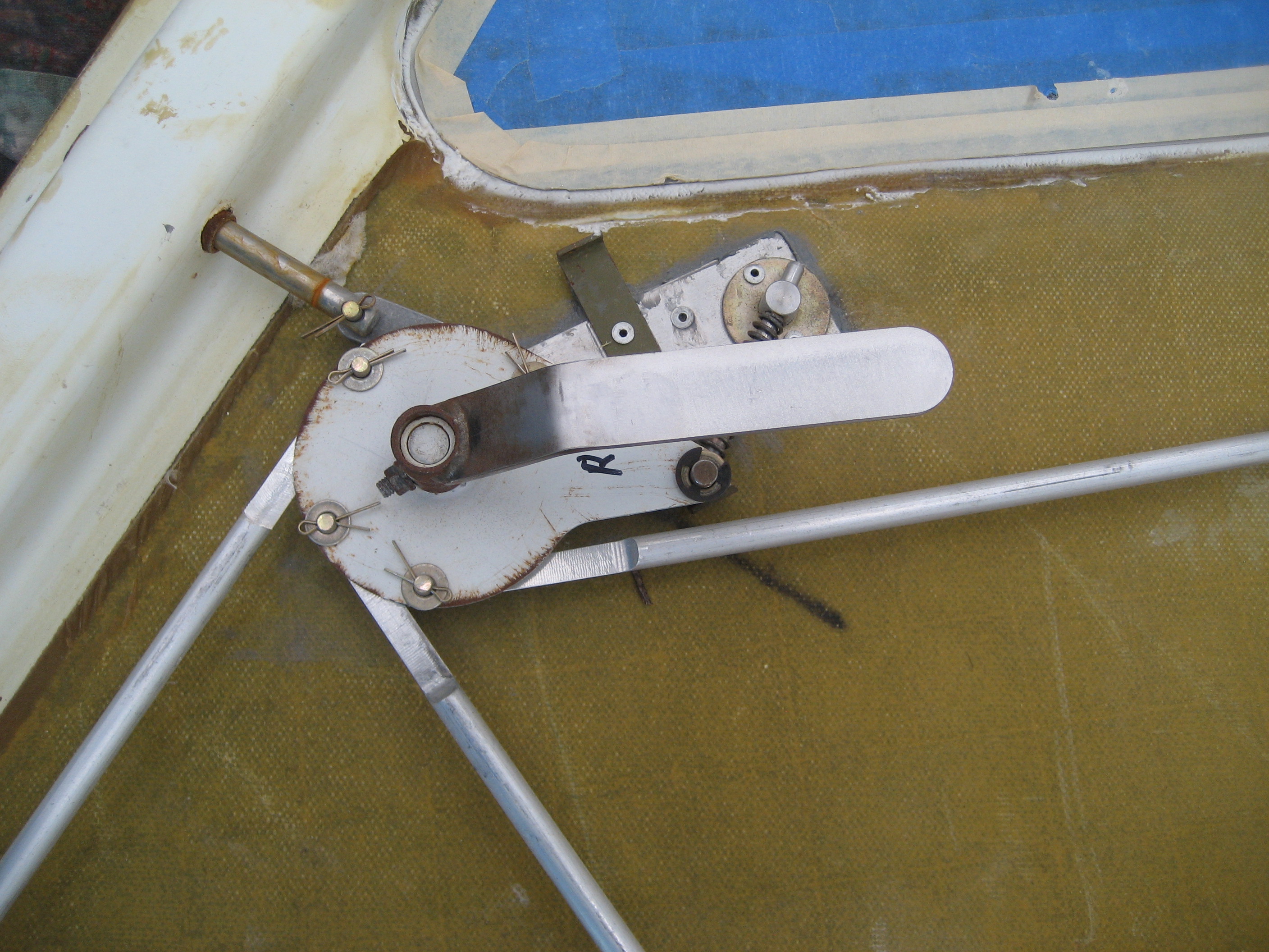
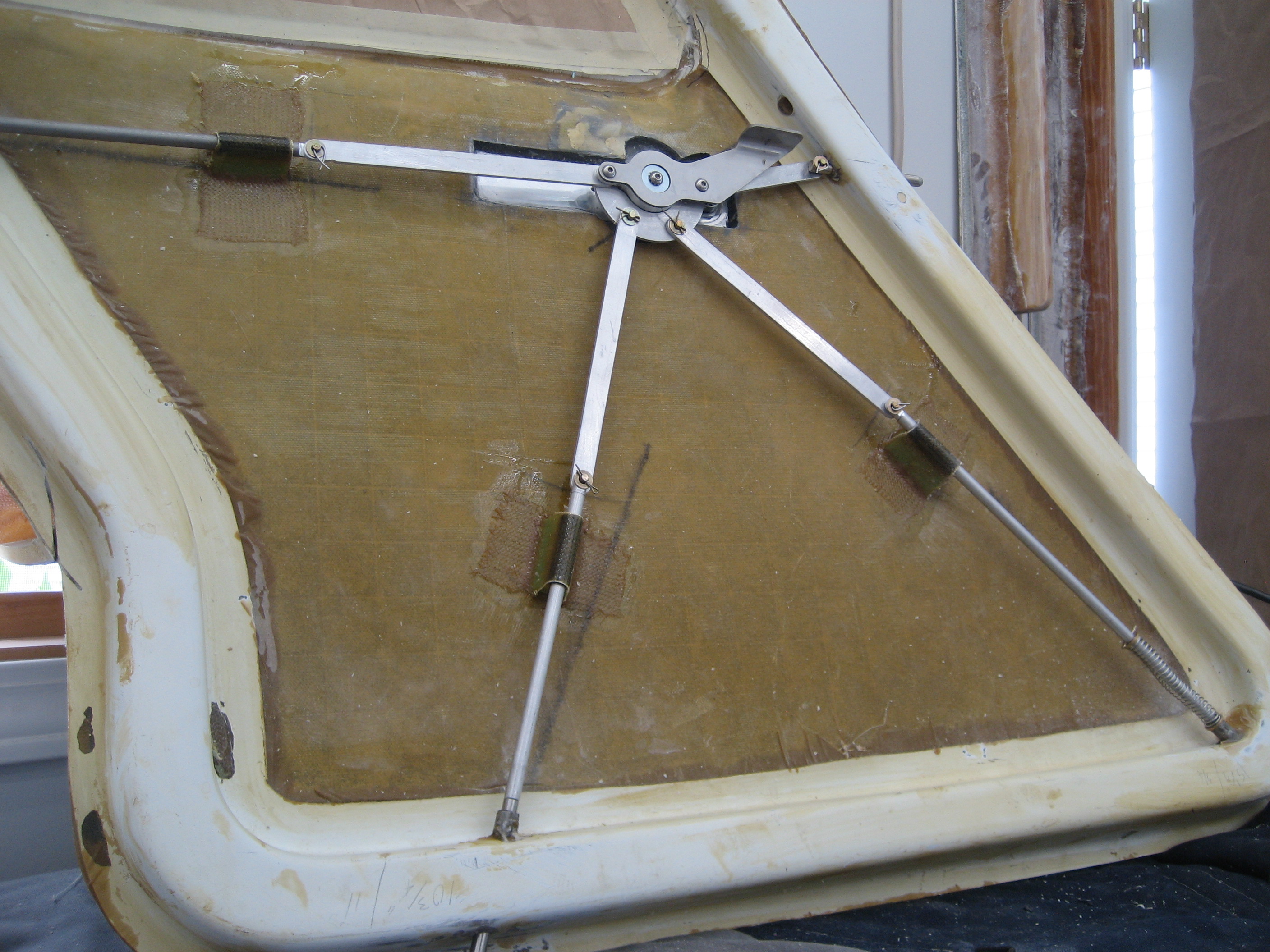
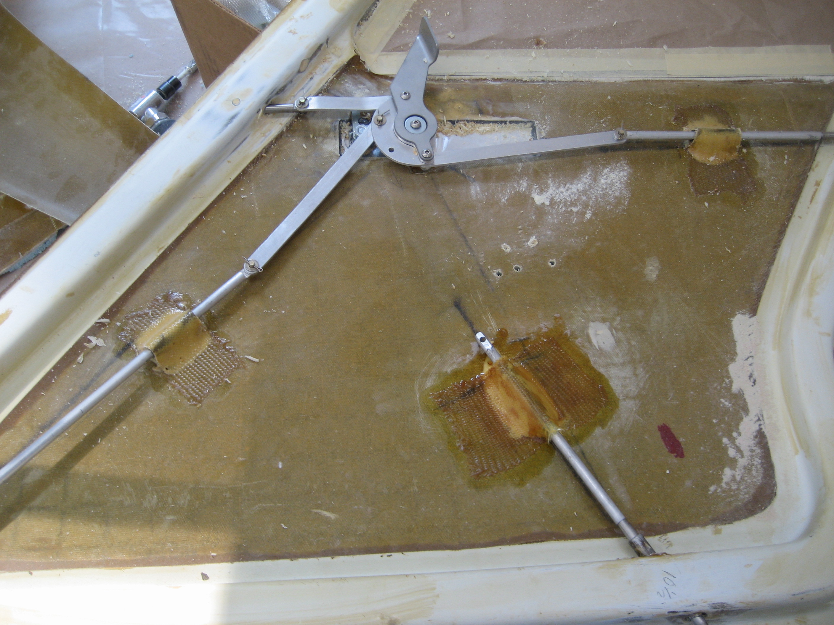
There are four pins that engage the doorframe to keep the door closed. These pins are attached to shafts that tie in to a cam that the door handle operates. The reason it’s so hard to operate is that when the cam rotates, the shafts move laterally and bind in the sleeves at the door edge. Except for the upper/forward pin. That one uses an intermediate link.


Here’s an animated gif that shows what’s happening.

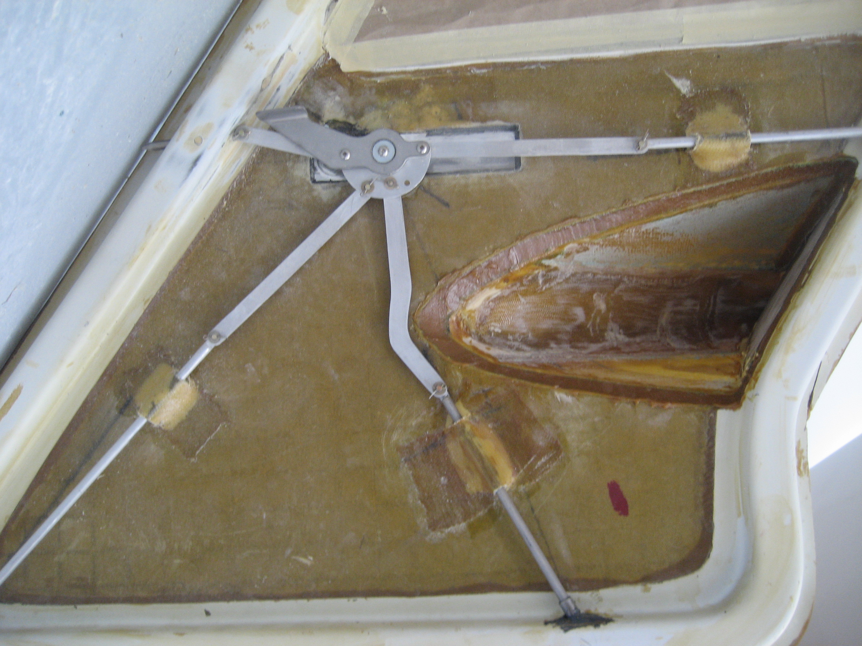
In a previous life, I was a repaired IBM Selectric Typewriters. They’re the typewriters with the golf-ball thing that bangs into the paper to make print. Something like over a thousand moving parts with almost 500 adjustments. It’s a wet dream for Rube Goldberg. So with that background, I was certain that I could build a better mechanism. The key was to keep the pins (and their attaches shaft) movement linear. That would require what I would call an intermediate link. So I make the shafts shorter, mounted a sleeve to maintain the alignment and built eight intermediate links.
Here’s the end result.
Closed to open


Over-center spring

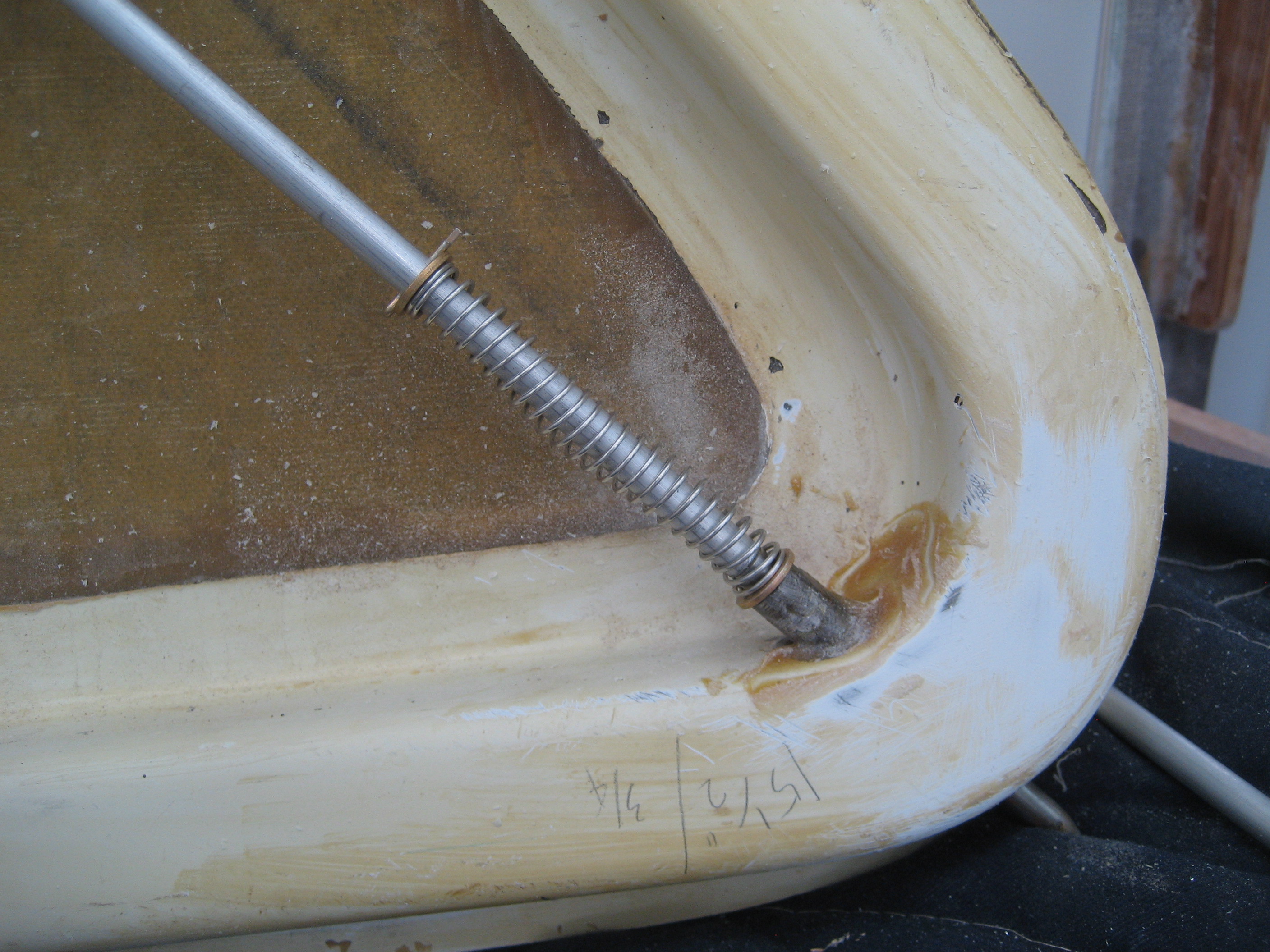
I located the holes in the cam so that the links would be over-center in the open and closed position. This is to keep the handle from opening (or closing) by itself. I also put a spring on one of the shafts to “load” the mechanism. This will apply pressure keeping the handle in the open or closed position.
Here’s a video (1 MB)
Then I had to remove the receiver sleeves in the door frame because they were set for the positioning of the old pins. Once I got them removed, I put the doors in just to give myself a pat on the back.
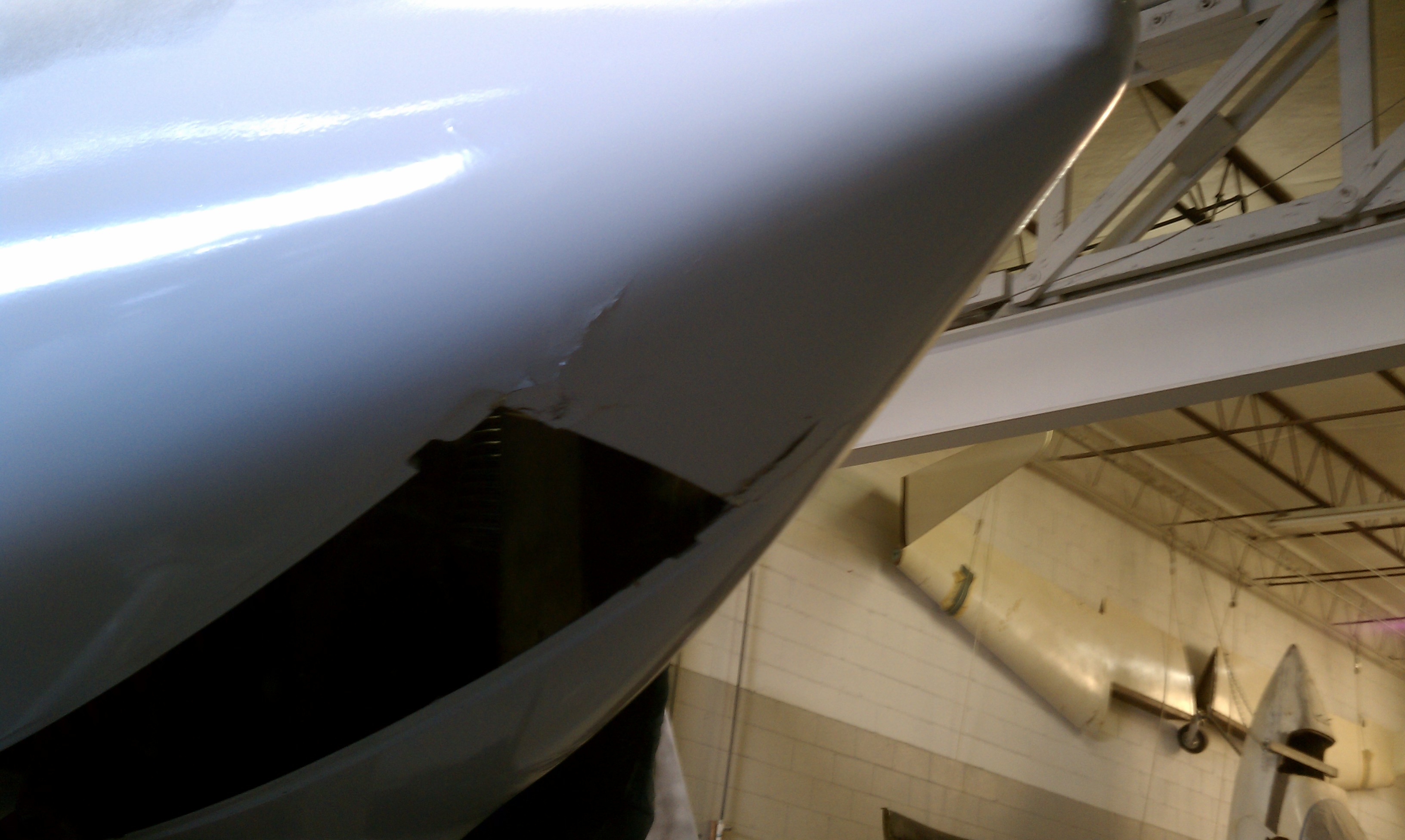
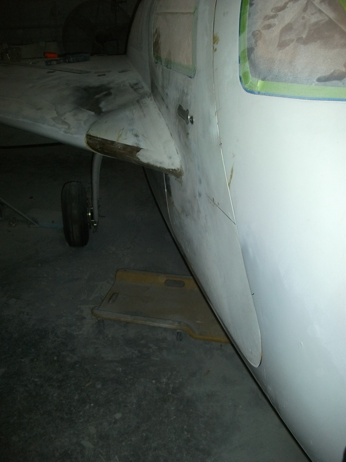
Right door.
Left door.

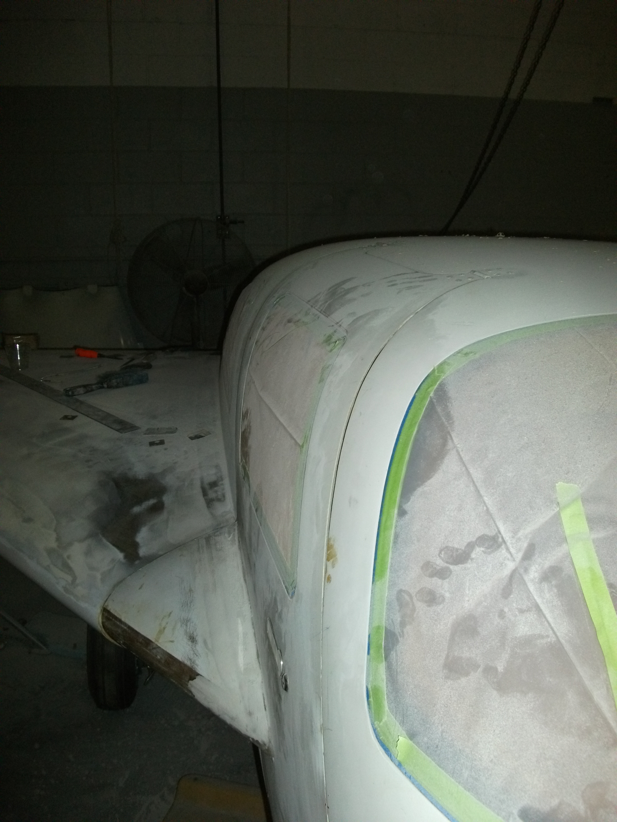
Uh-oh. Something doesn’t look right on the right door. So let’s play “Find Waldo” and see if you can tell what’s not… good.
I’ll wait.
Did you find it?
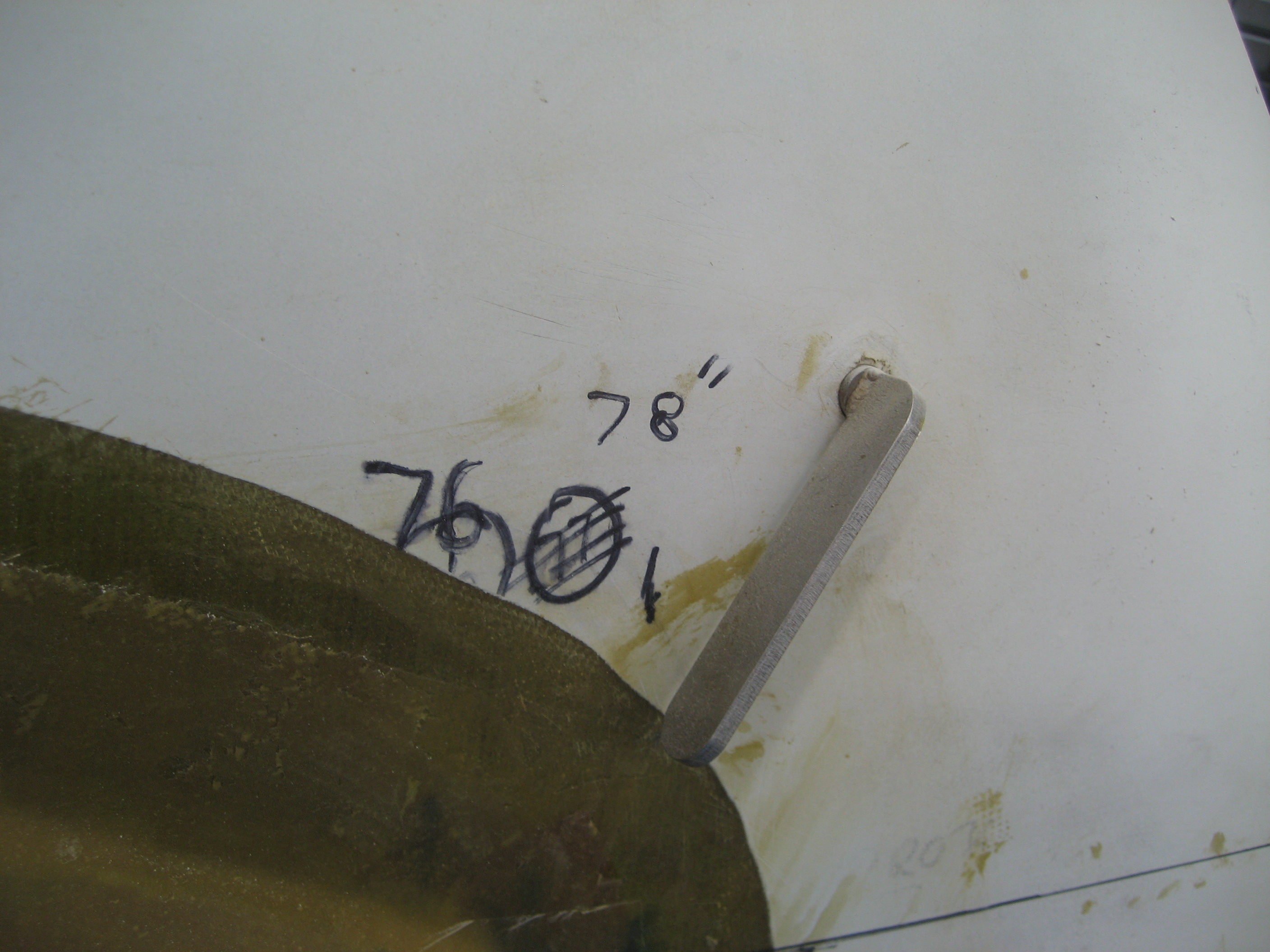
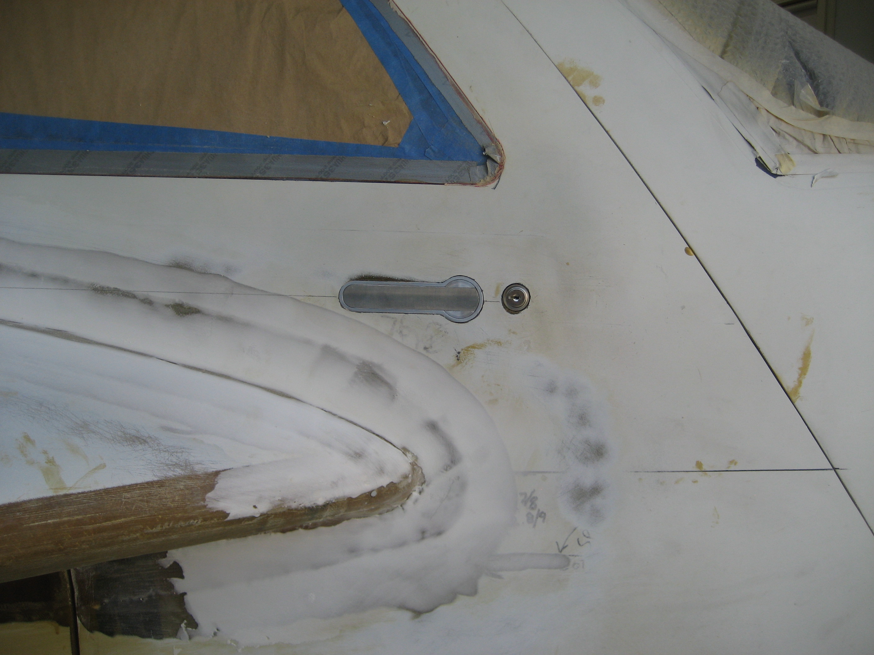
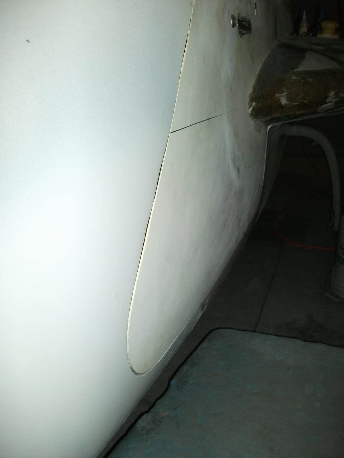
Here’s a close up.
It’s not level! I put these marks on the outside but all the cutting is done on the inside. Somehow, I put the door handle in and didn’t check the outside alignment. I thought about for about 5 minutes before deciding to remove the handle to correct it. I know it’s only off by about 1/8″. But there’s the slippery slope. If you let this slide, it makes it easier to let the next thing go and pretty soon you’re flying something that’s held together with duct tape and bailing wire. Besides, what if I put a stripe down the side of the fuselage and it’s right next to the handle? Then it’s really stick out!
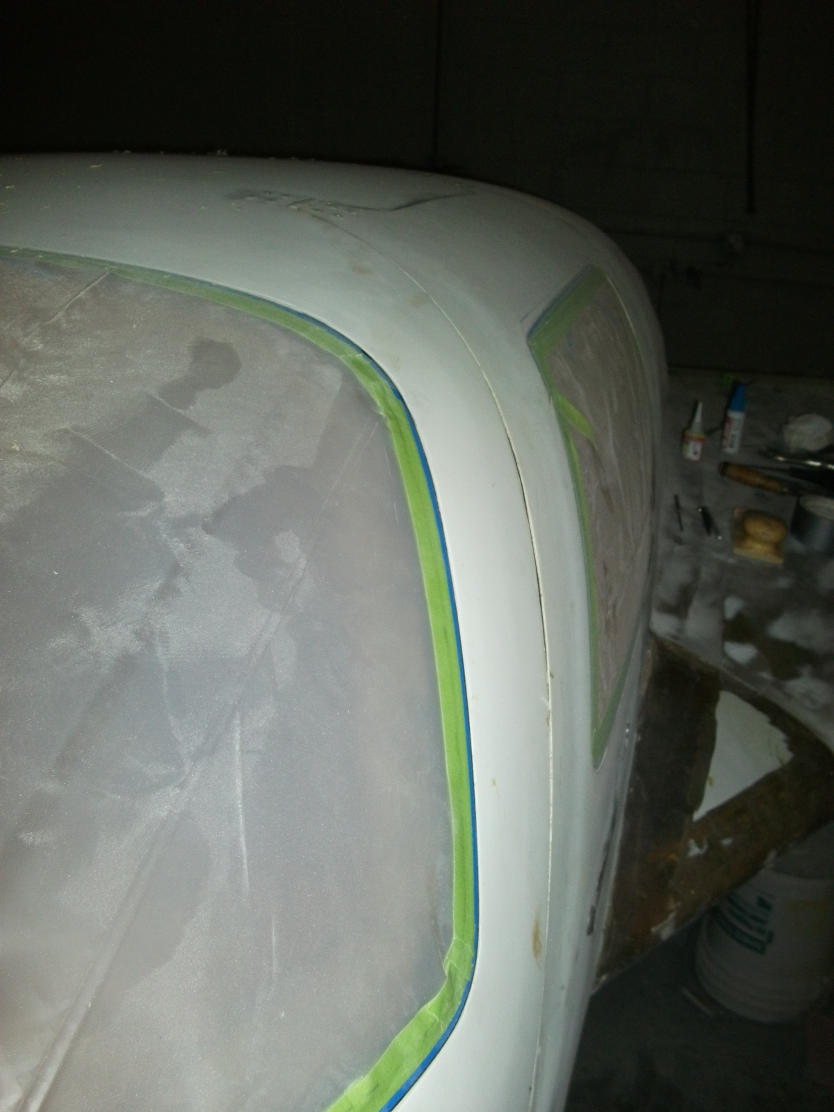
Removing the handle, enlarging the opening and epoxying the handle back in only took about two hours so it wasn’t a huge issue.


