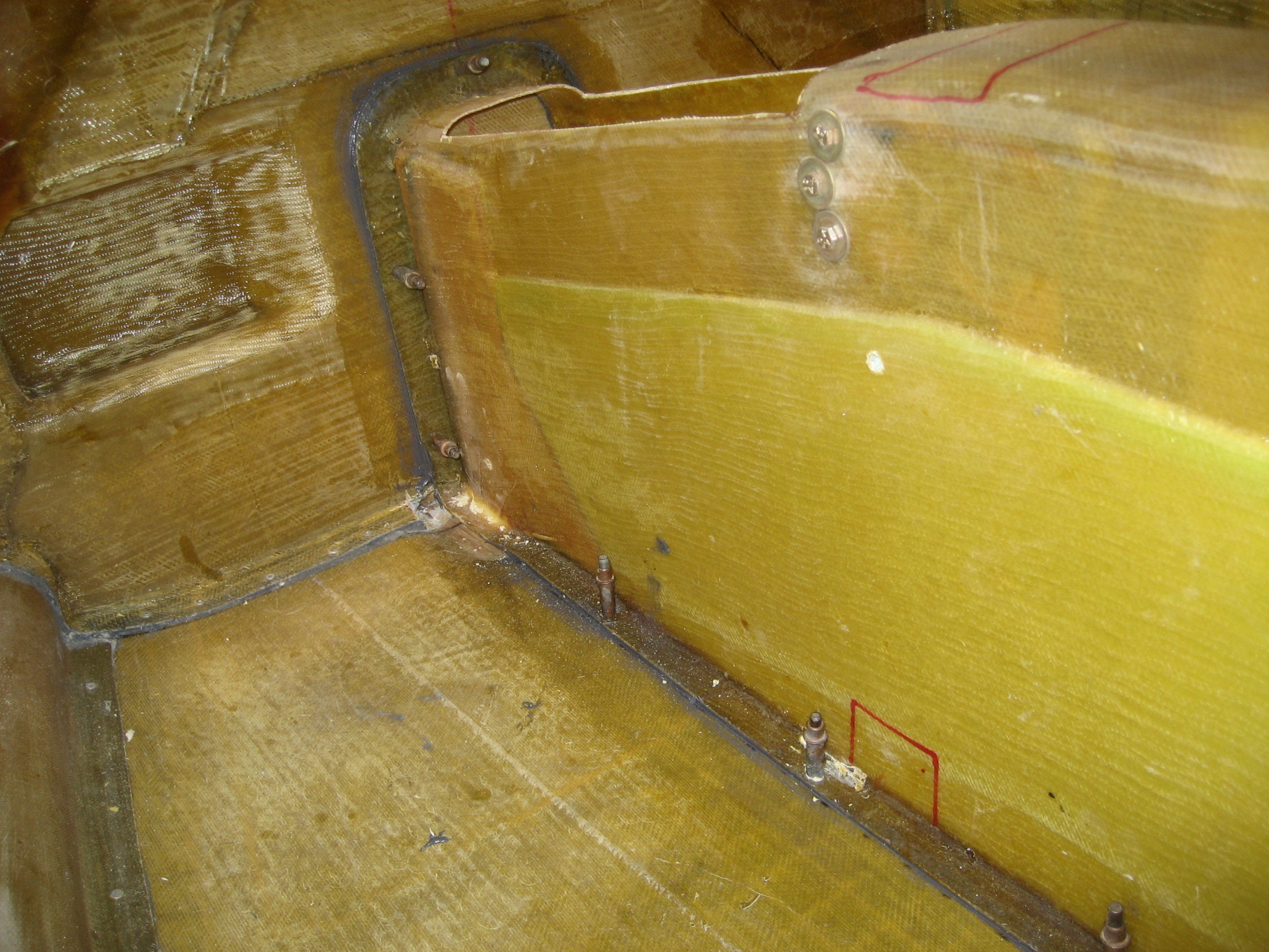
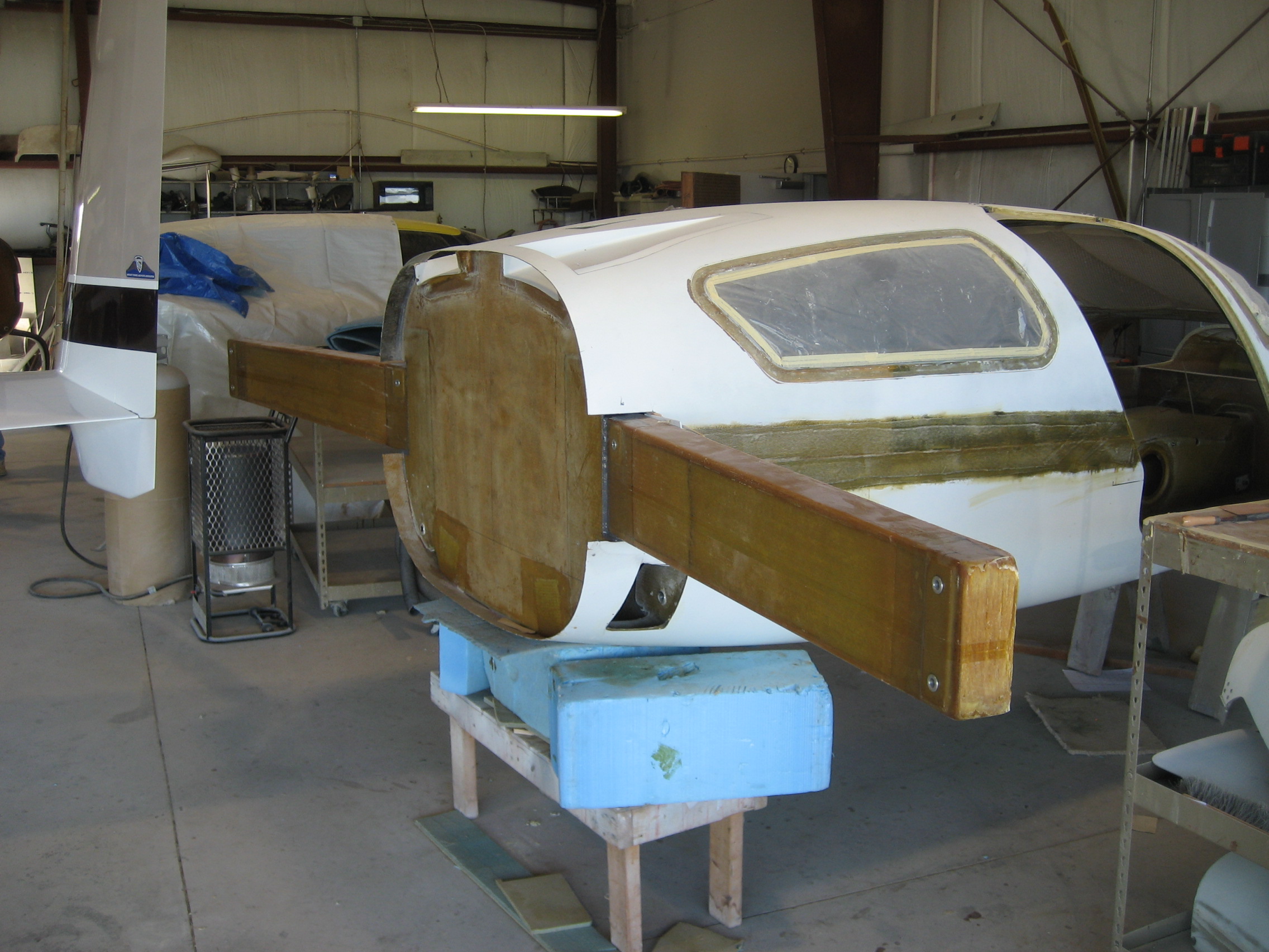
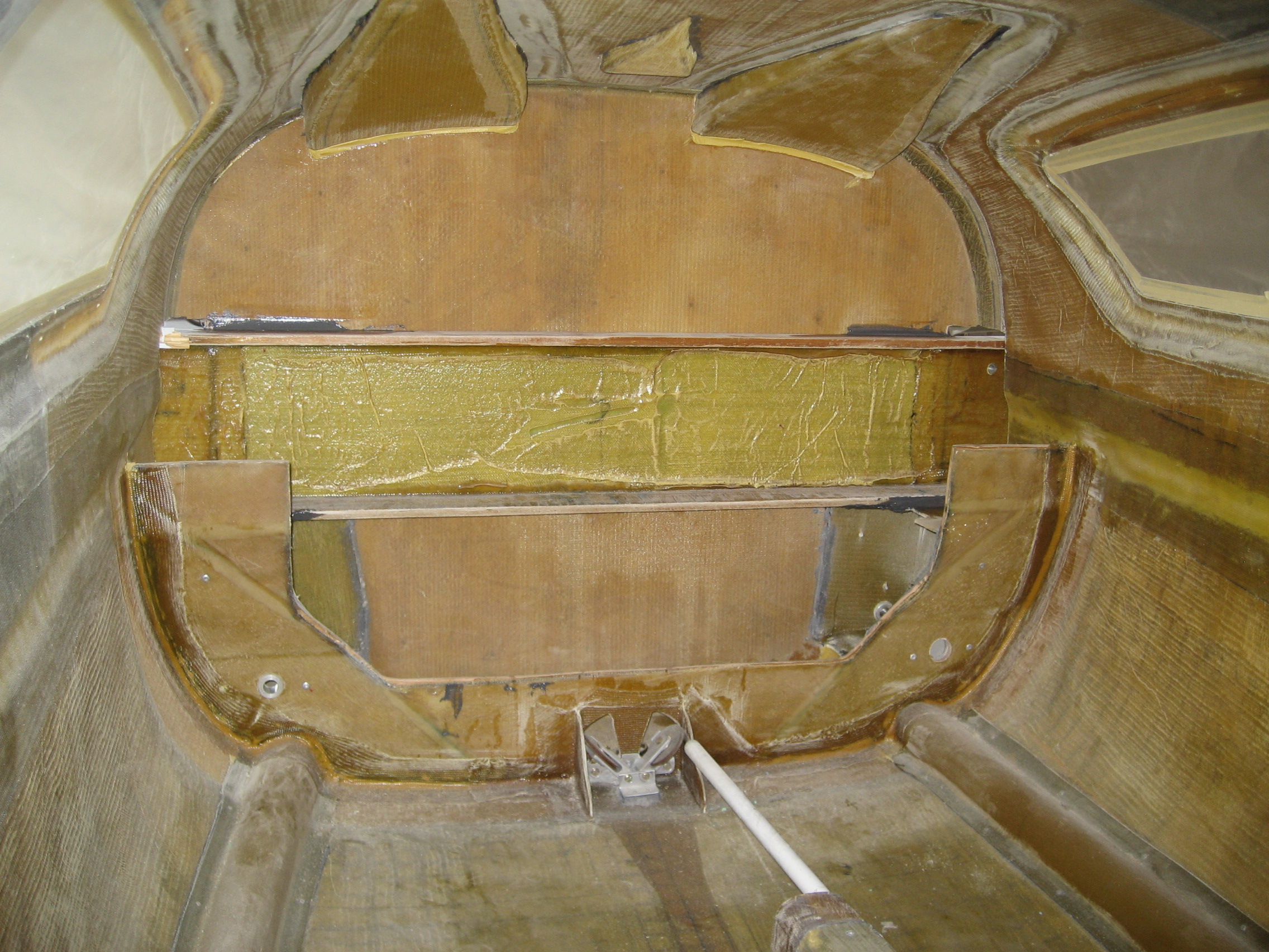
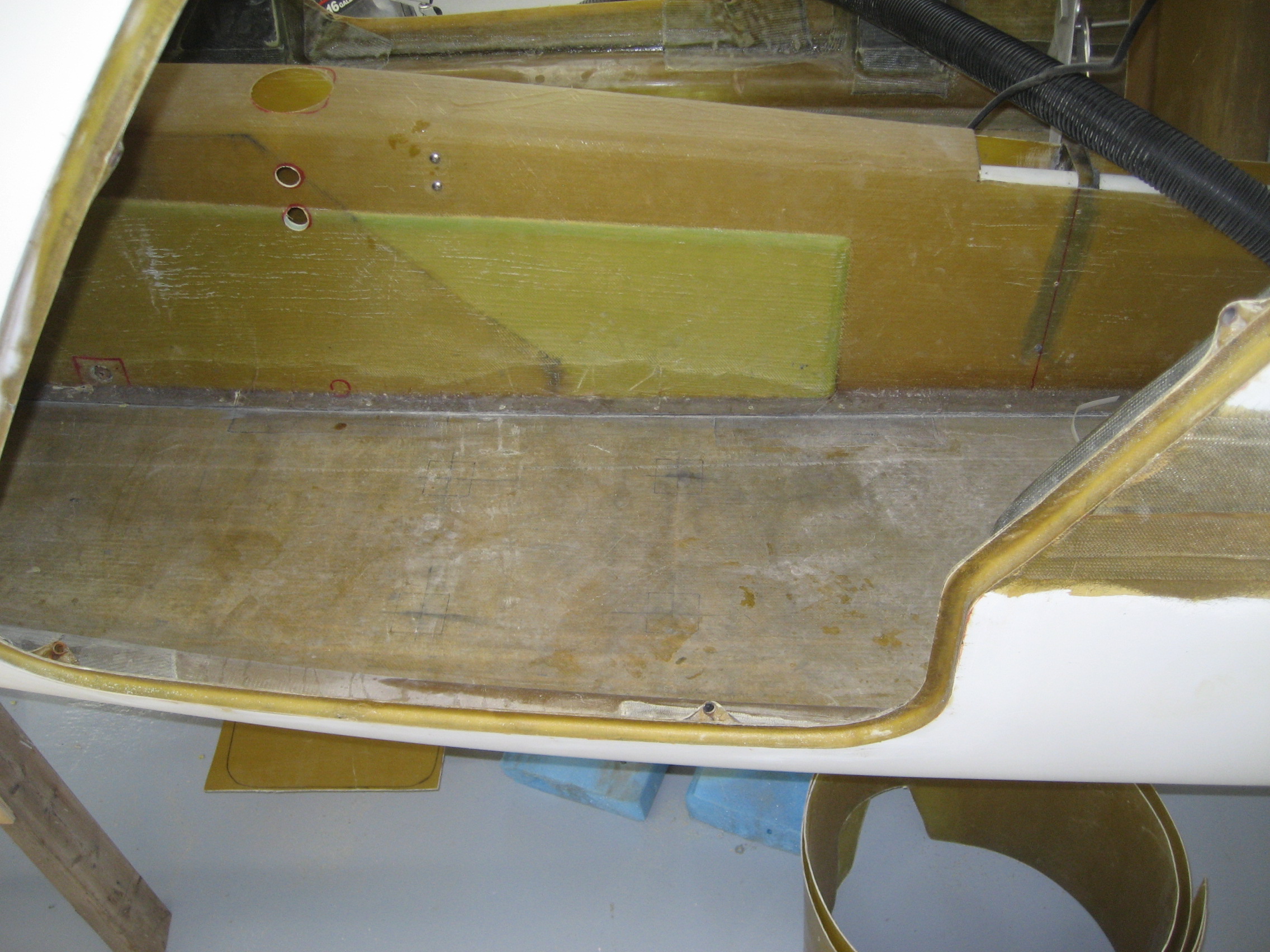
Next was front seat hardpoints. This is where the front seat are bolted to the floor.
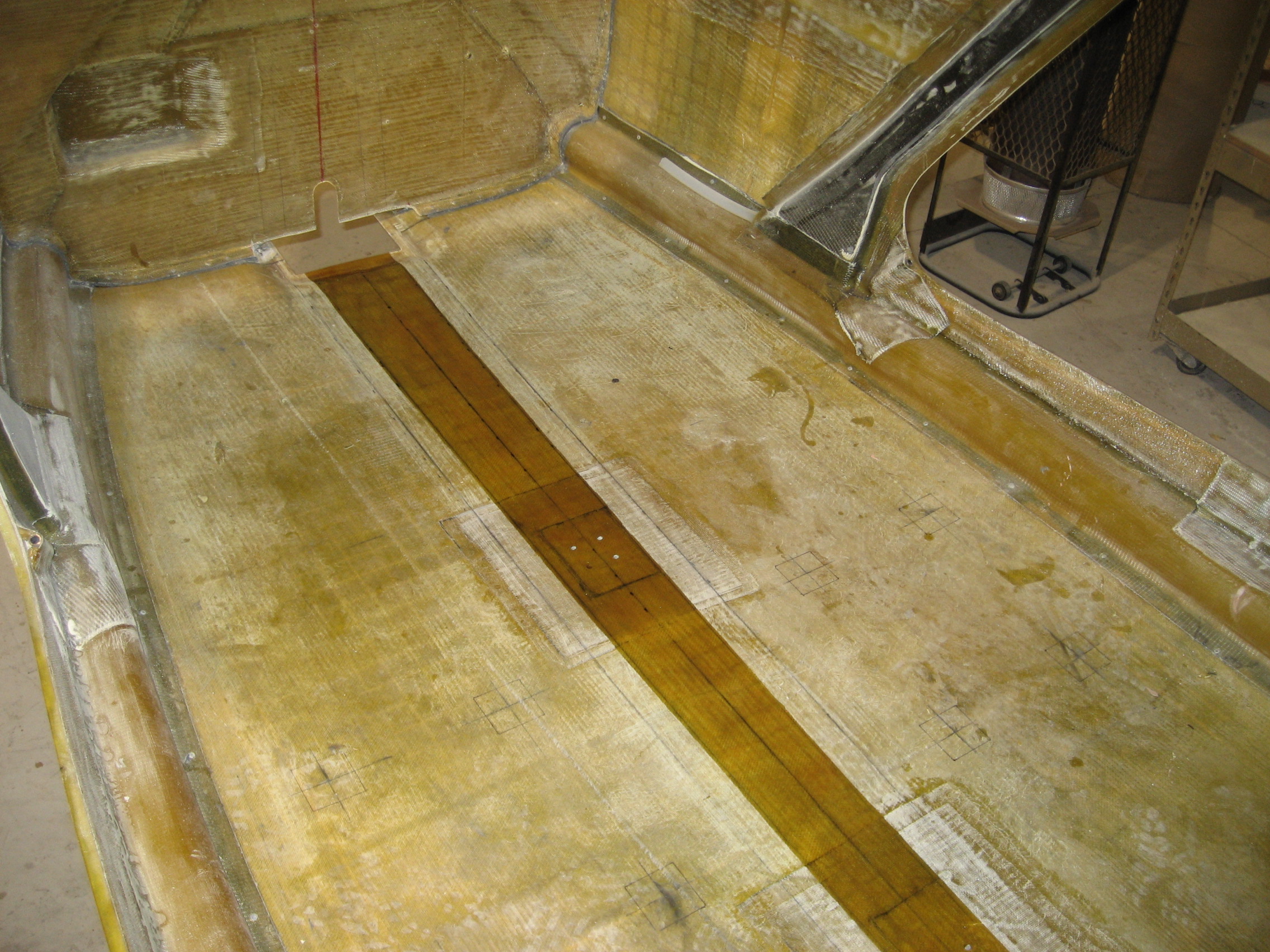
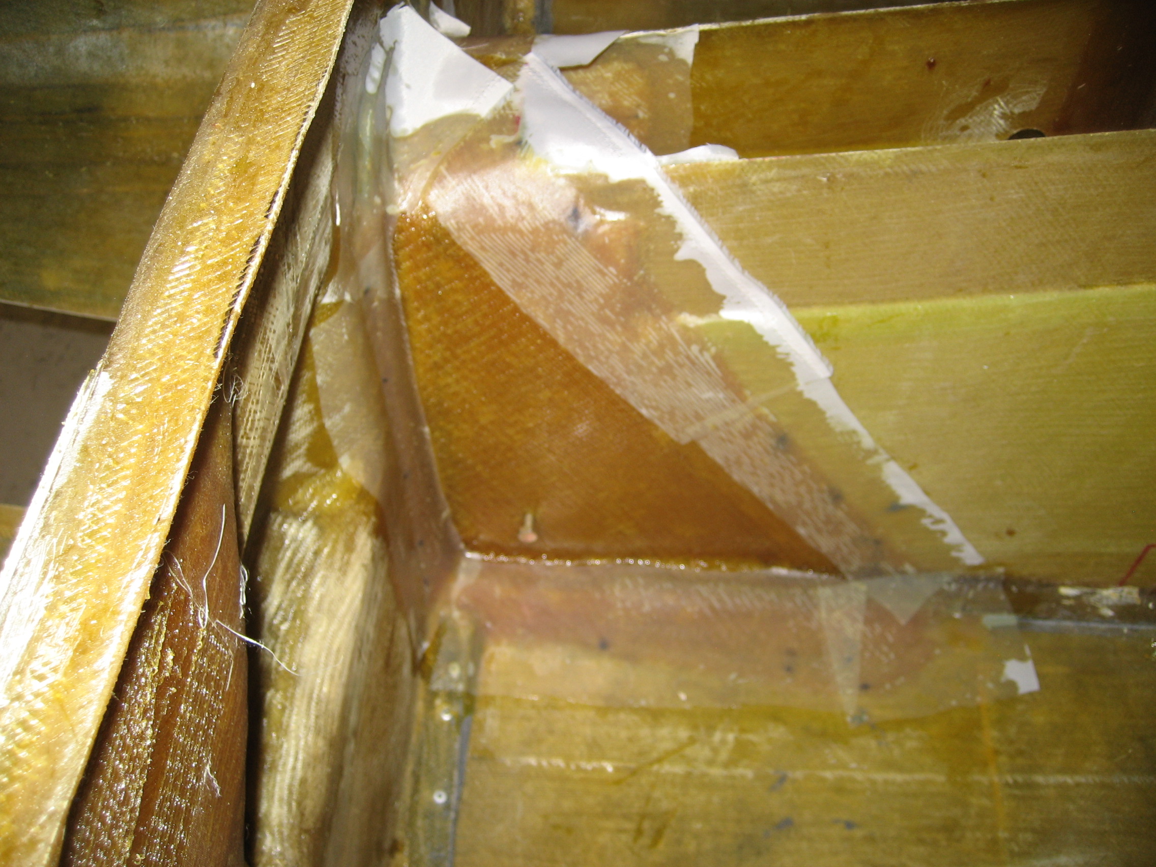
This is a view of the floor looking froward where the pilot seat will be. On the right is the keel and the left (just out of view) is the door opening.

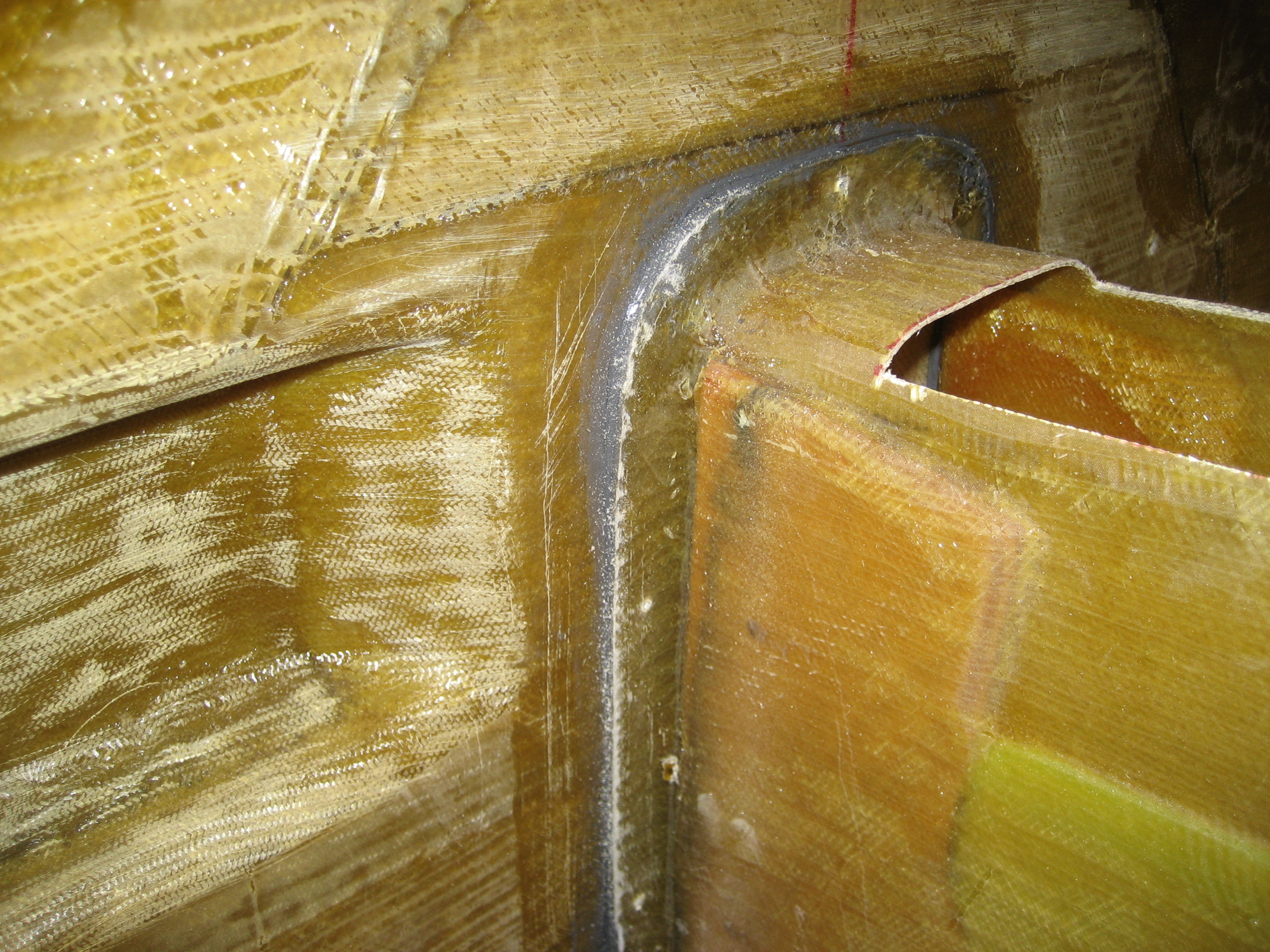
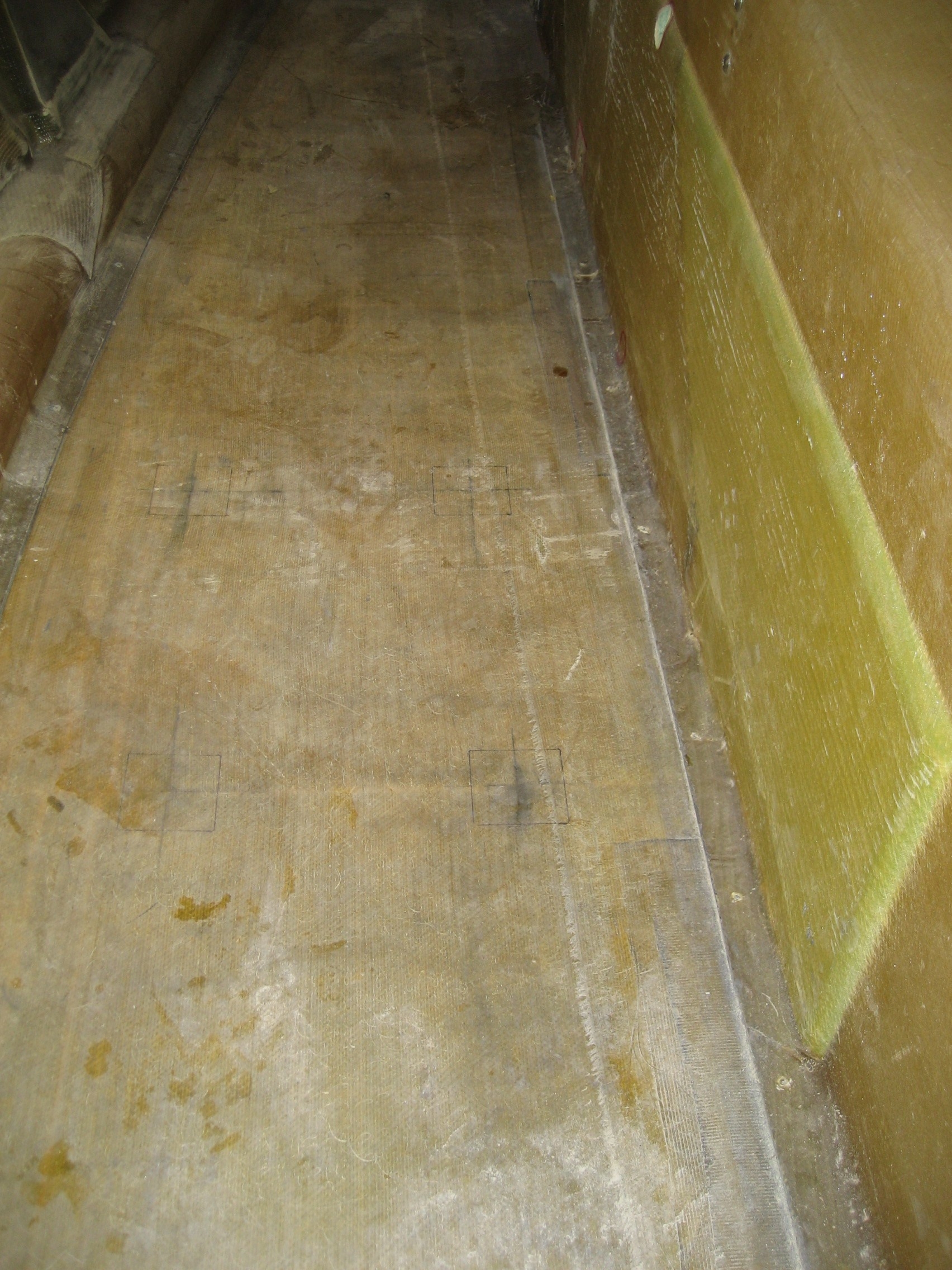
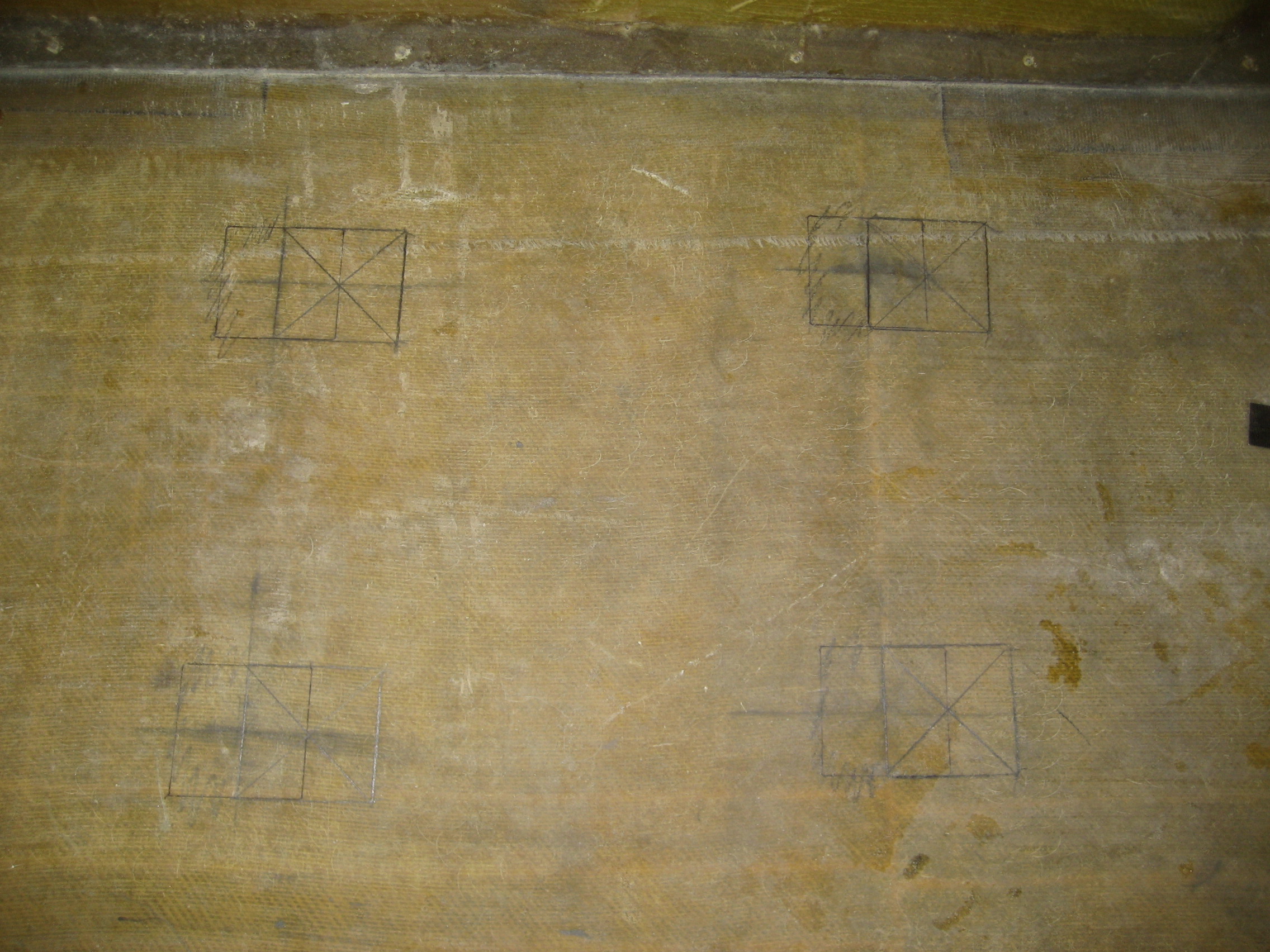
This is looking at the floor from the pilot side door. I’ve laid out the positions of the 2″x2″ square hardpoints according to the manual.


But wait, I’m a bit taller than the average person. So I decided to make a engineering change and move the pilot seat back an inch.

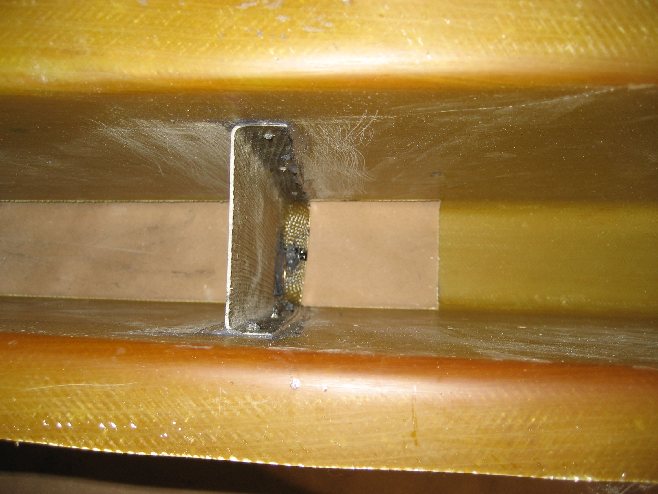
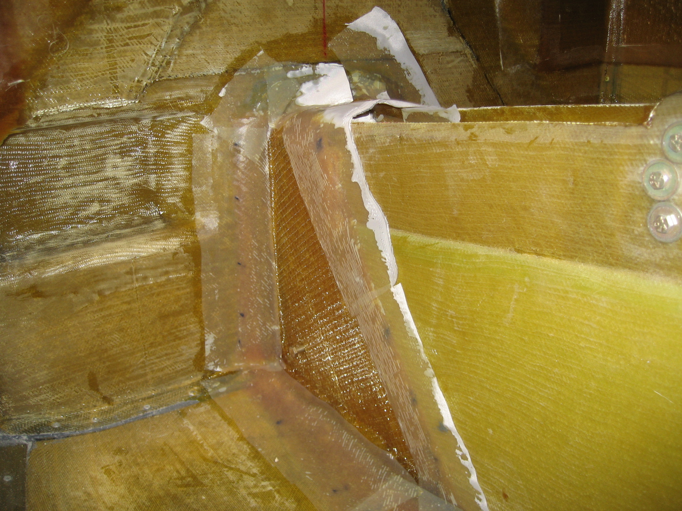
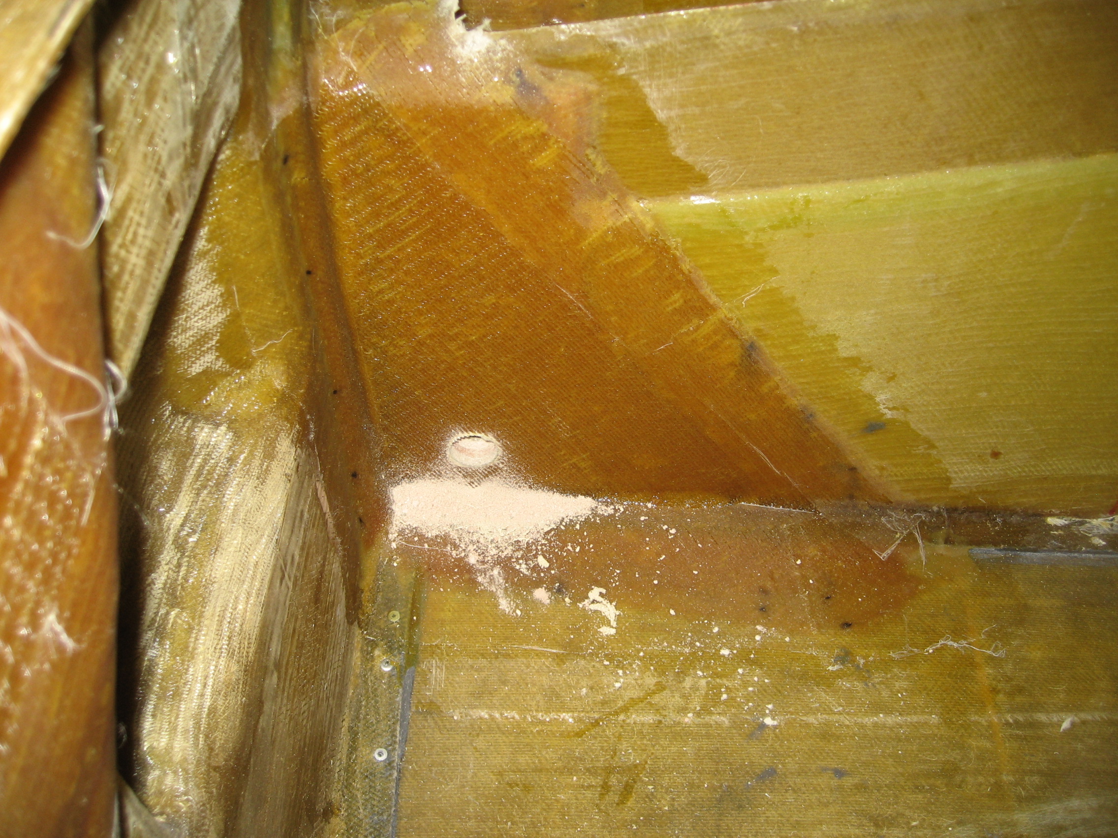
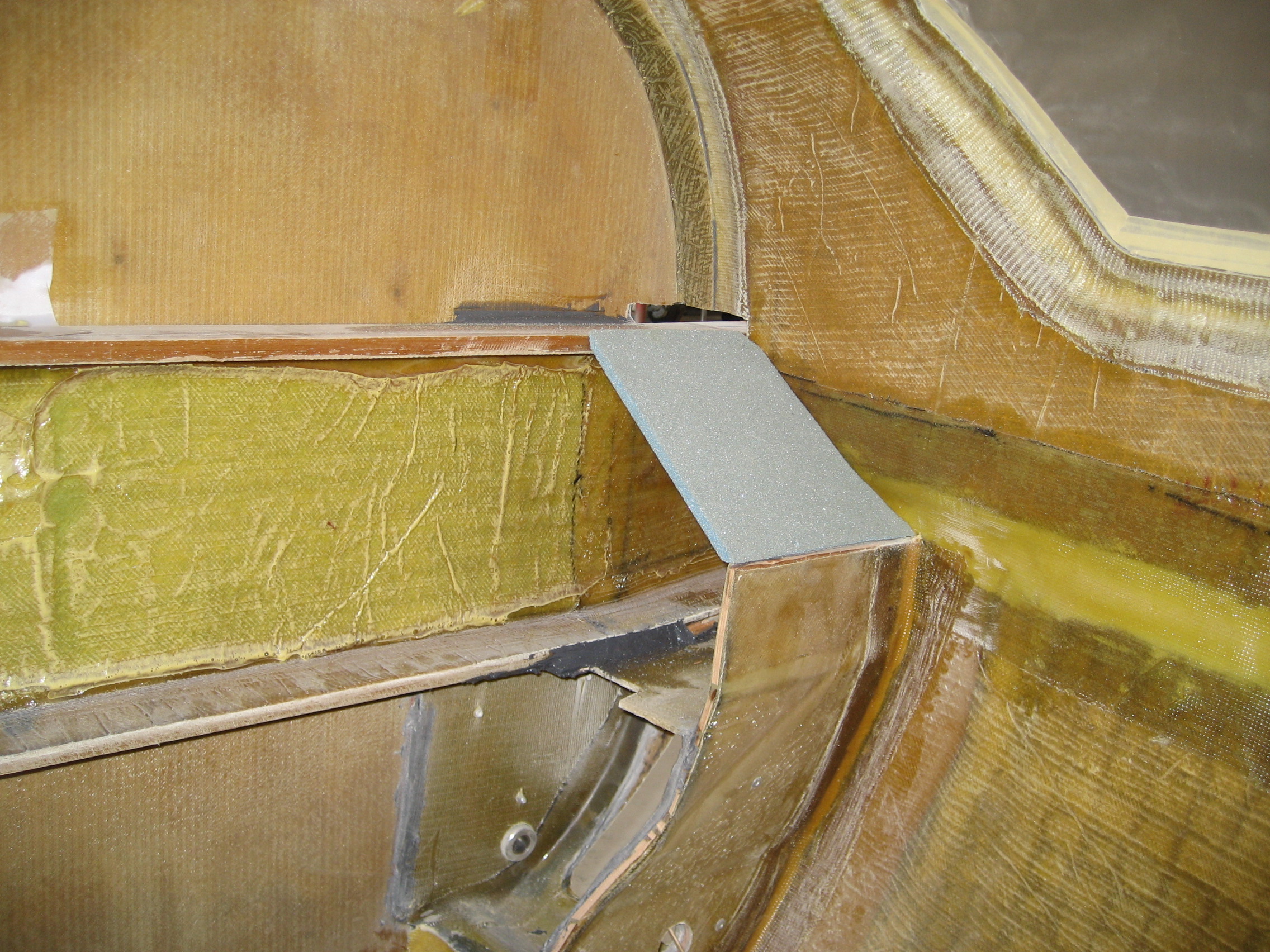
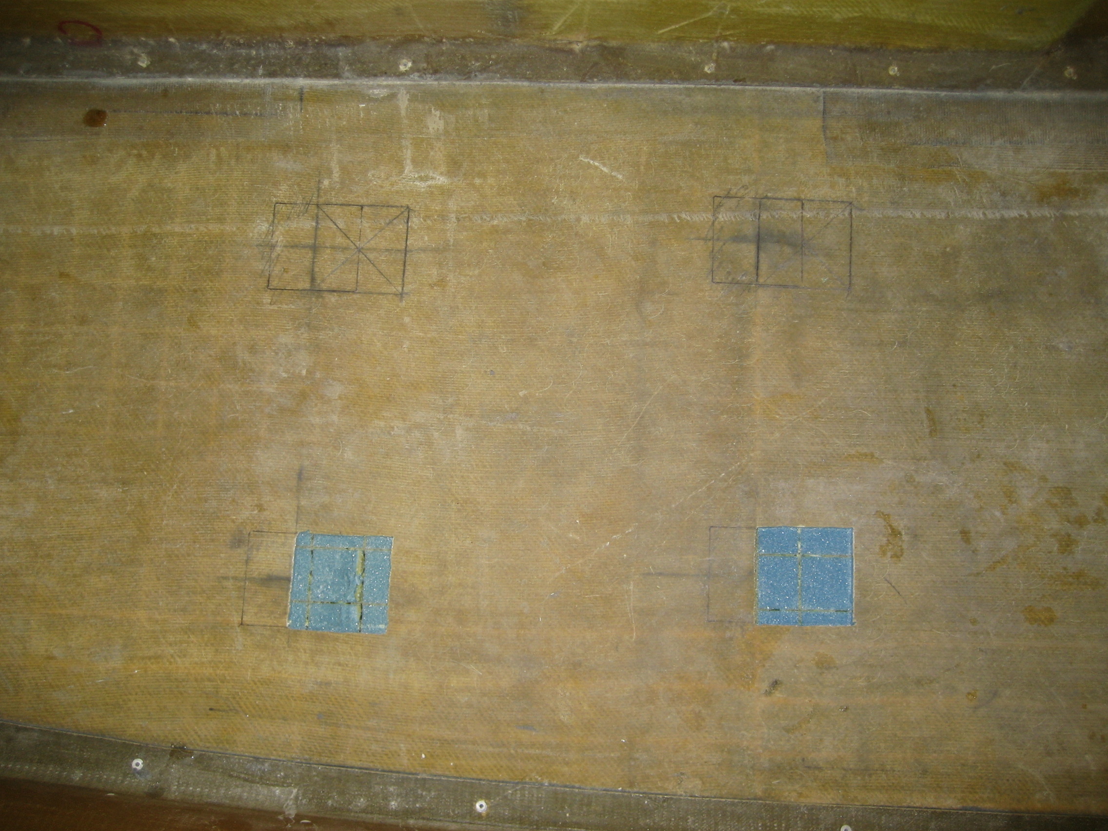
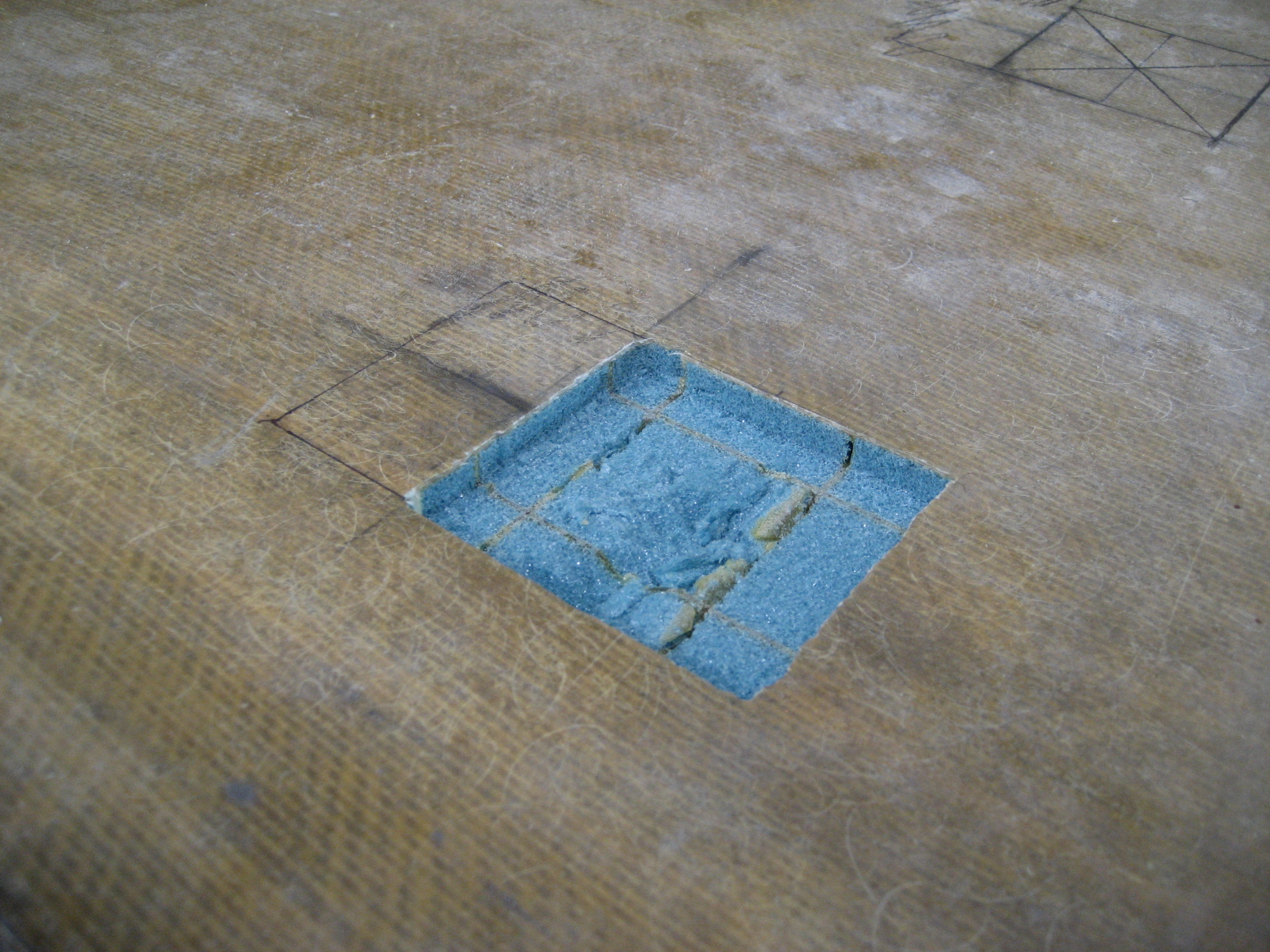
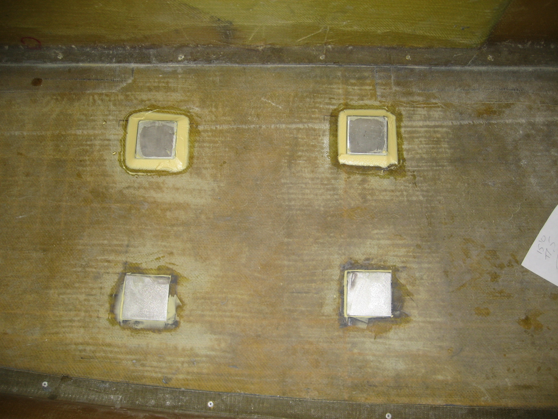
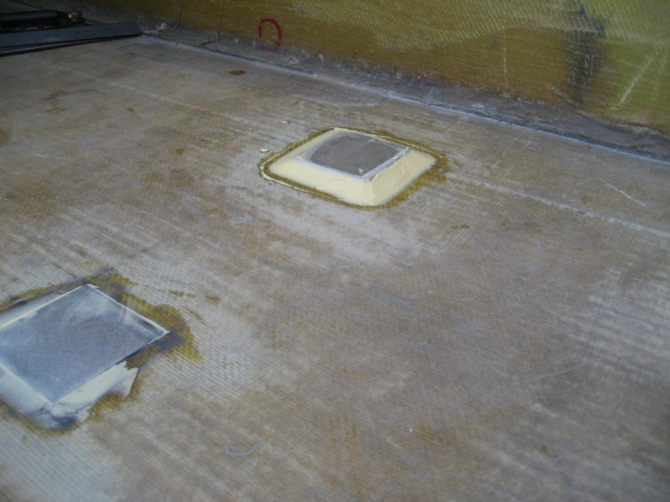
Because the floor is not flat (it’s lower in the center than on the sides), the outboard hardpoints have to be recessed so the the seat will be level. Here’s where one of the outboard hardpoints will go.


The next temporal black hole was how to attach initially. They’re going to have two layer of BID over them, but what to stick them on with to hold them in place. One place in the manual said:
“The inboard hardpoints can be installed on the surface and covered with two plies of BID.”
The other place said “Alphapoxy”. Now I haven’t had an occasion to use that before but my understanding is that it’s a lightweight epoxy. Now there’s going to be two layers of BID over top and that’s where the strength is going to come from so it probably doesn’t make THAT much difference but when in doubt, I’m going to spend time to remove all doubt. So after reading and re-reading, I gave up and called the factory. Turns out it doesn’t really matter. ARRGH! Another hour wasted. Maybe I should ship it back to Florida and spend a week every month down there?
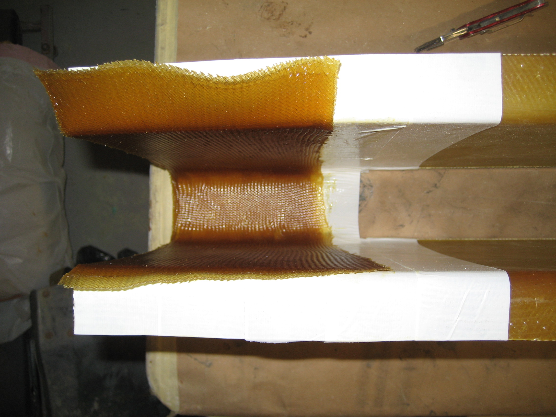
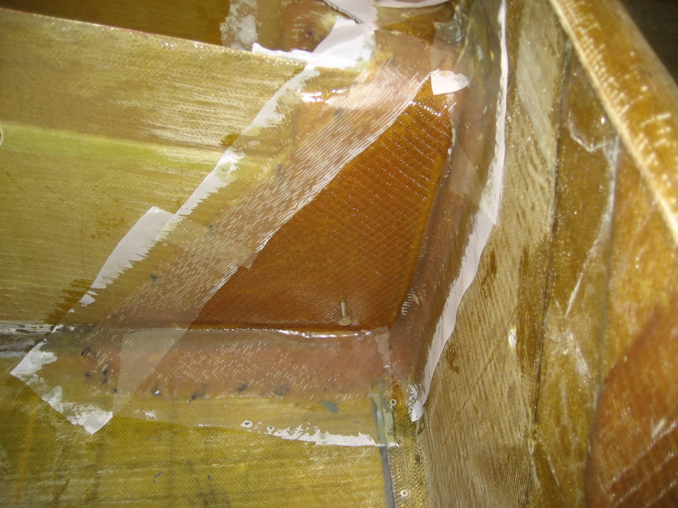
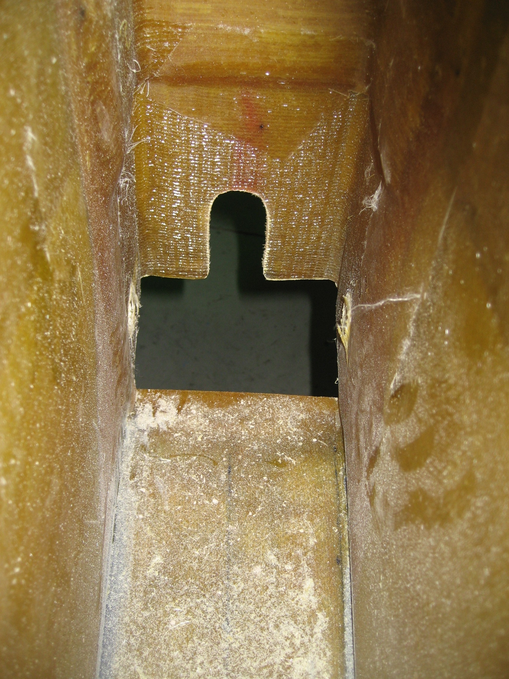
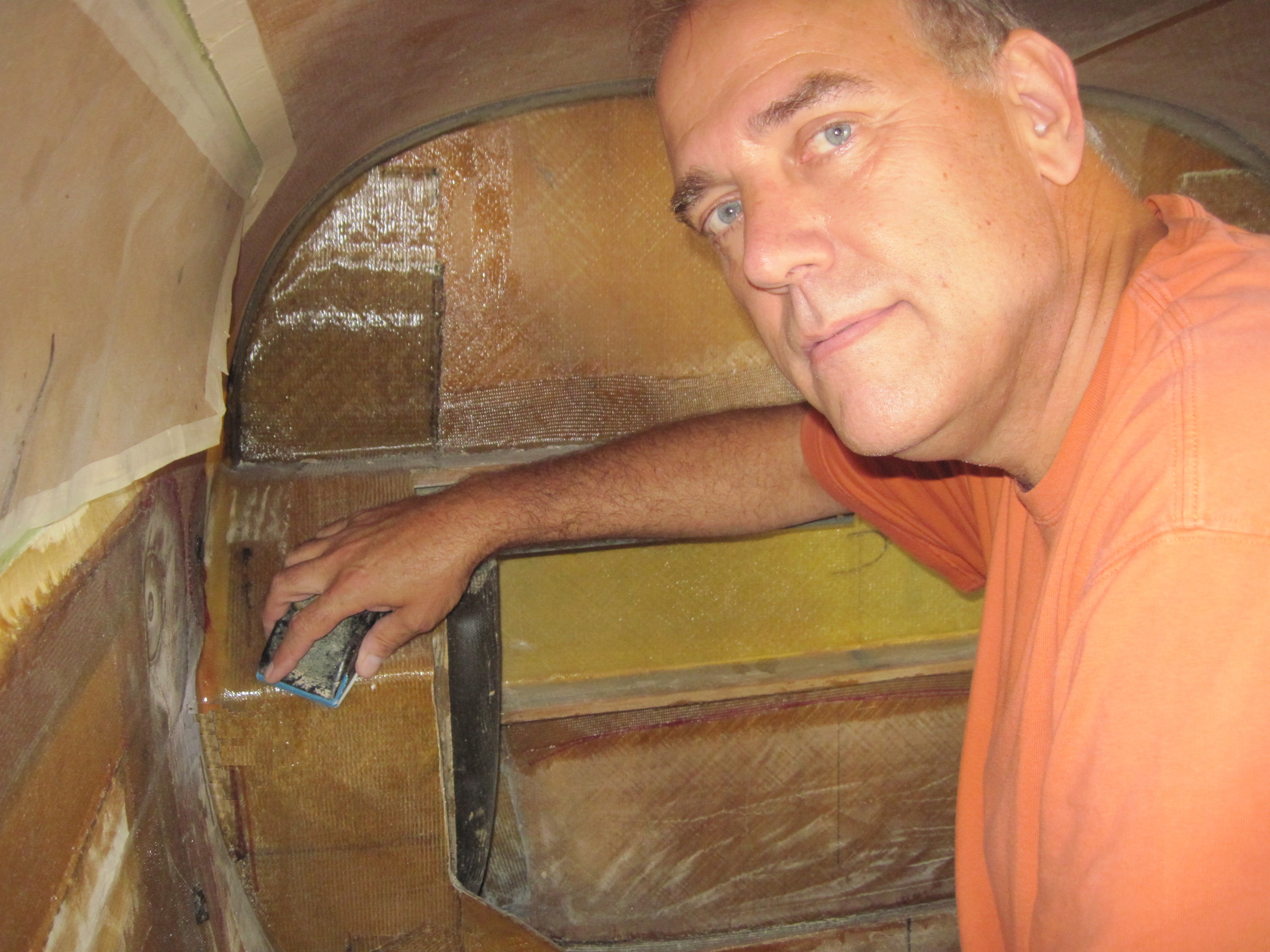
Here are the hardpoints in place with micro bevel ready for BID layups.