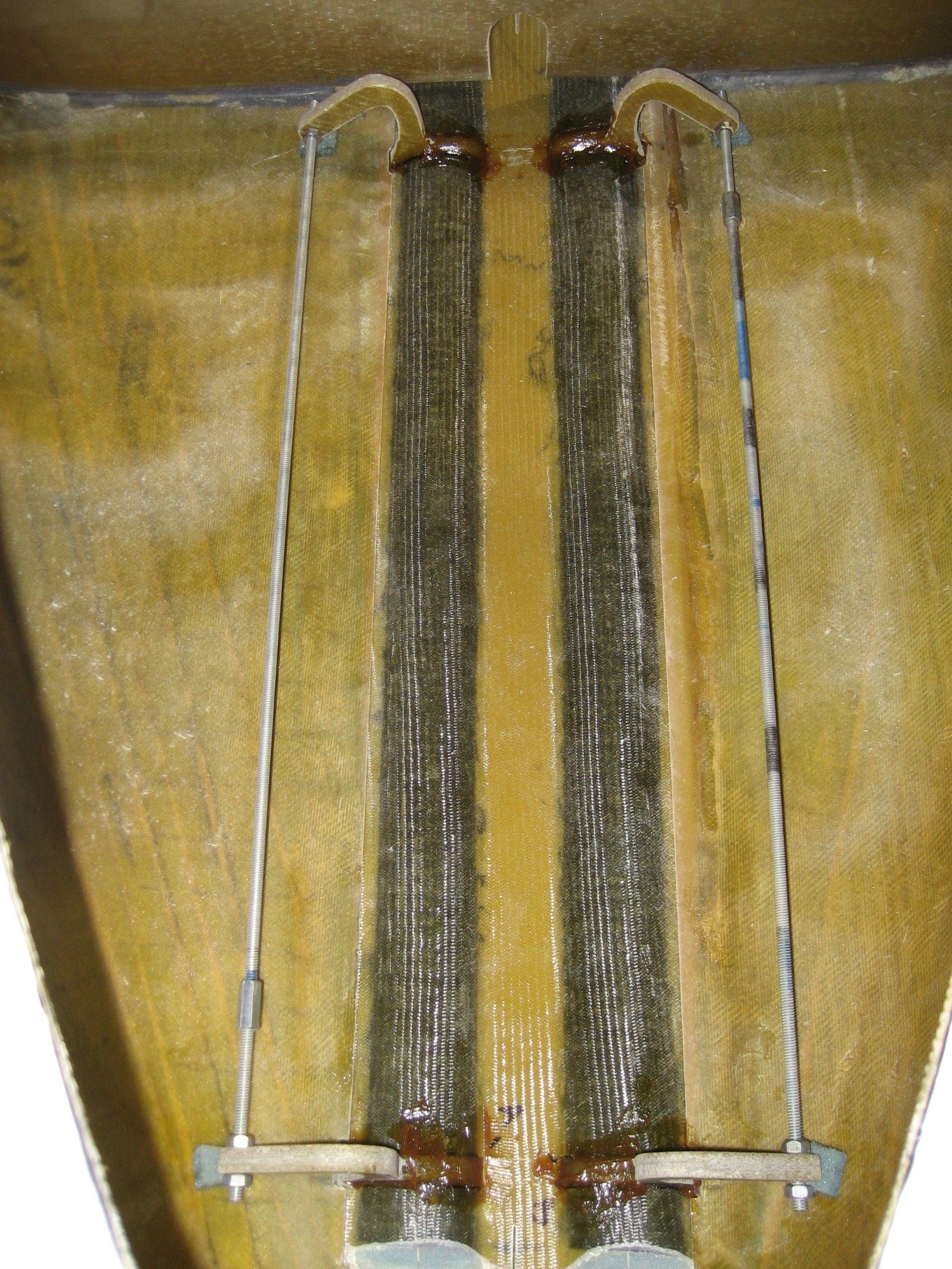
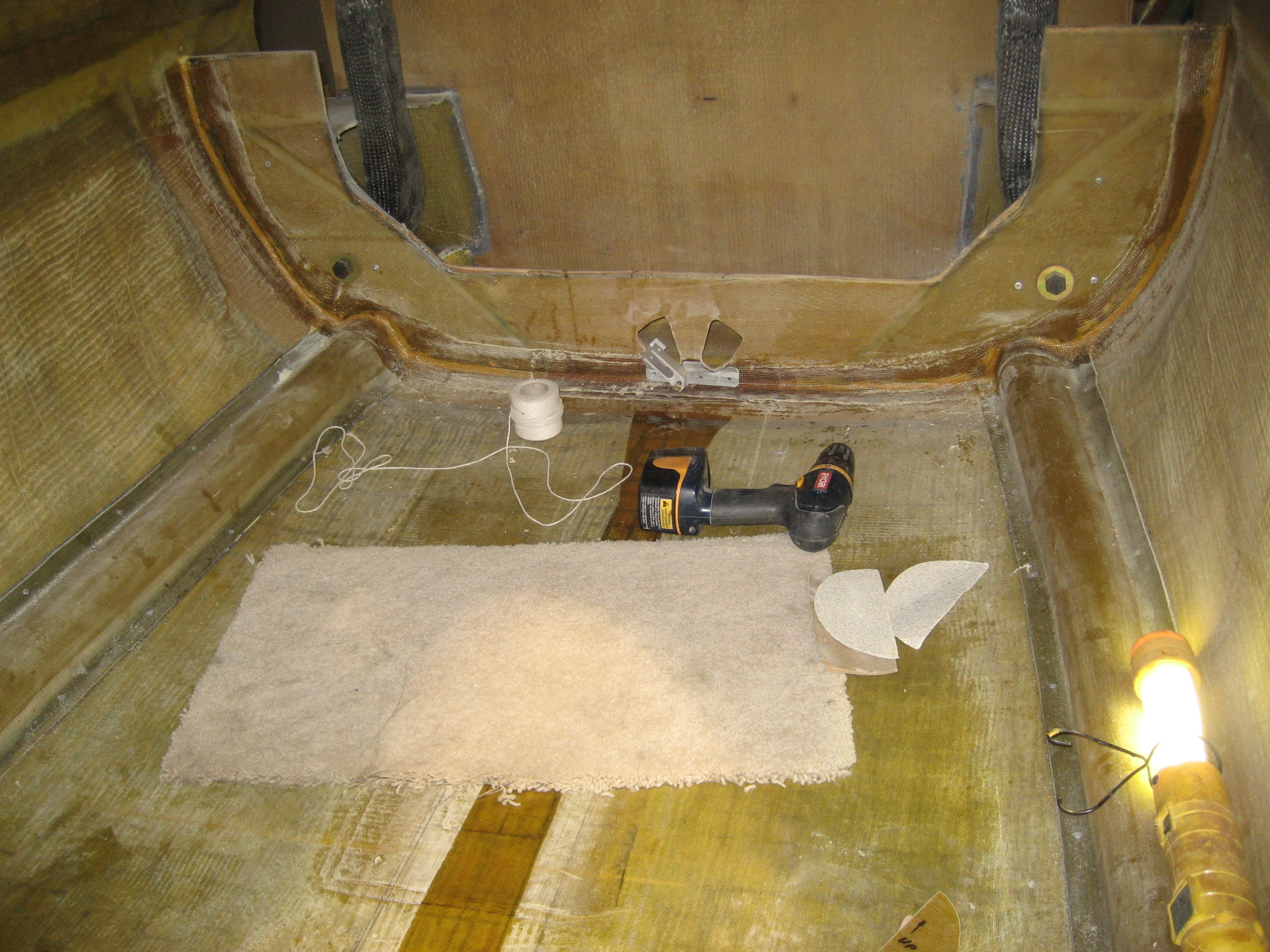
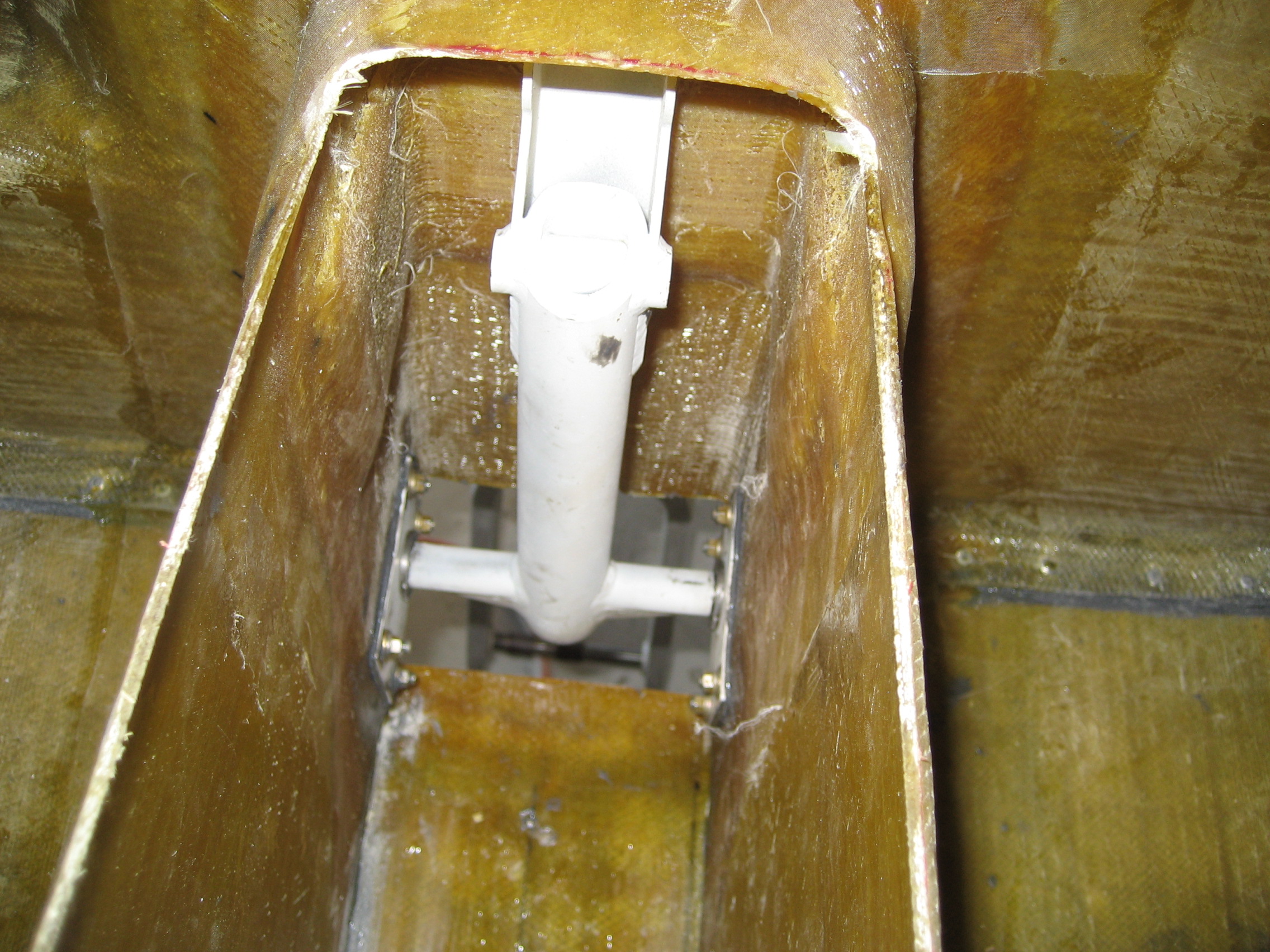
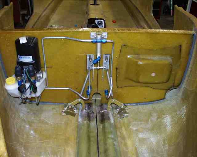
I decided to continue with the last thing I was working on in Florida (Main Landing Gear – MLG). When they build the fuselage, They mount the MLG but only to the point that they can roll the fuselage around. They won’t retract. The first task was open up the side of the fuselage so the legs could come up.
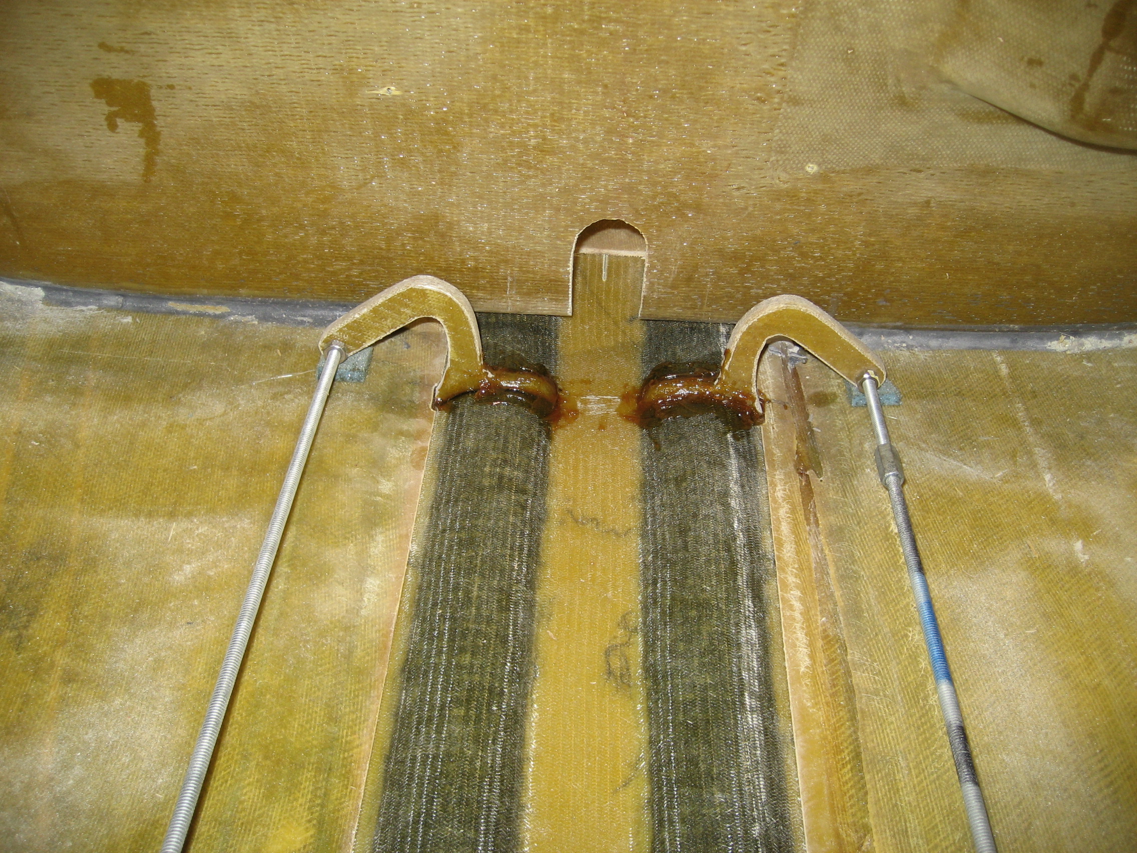
Here’s the left side main gear leg.

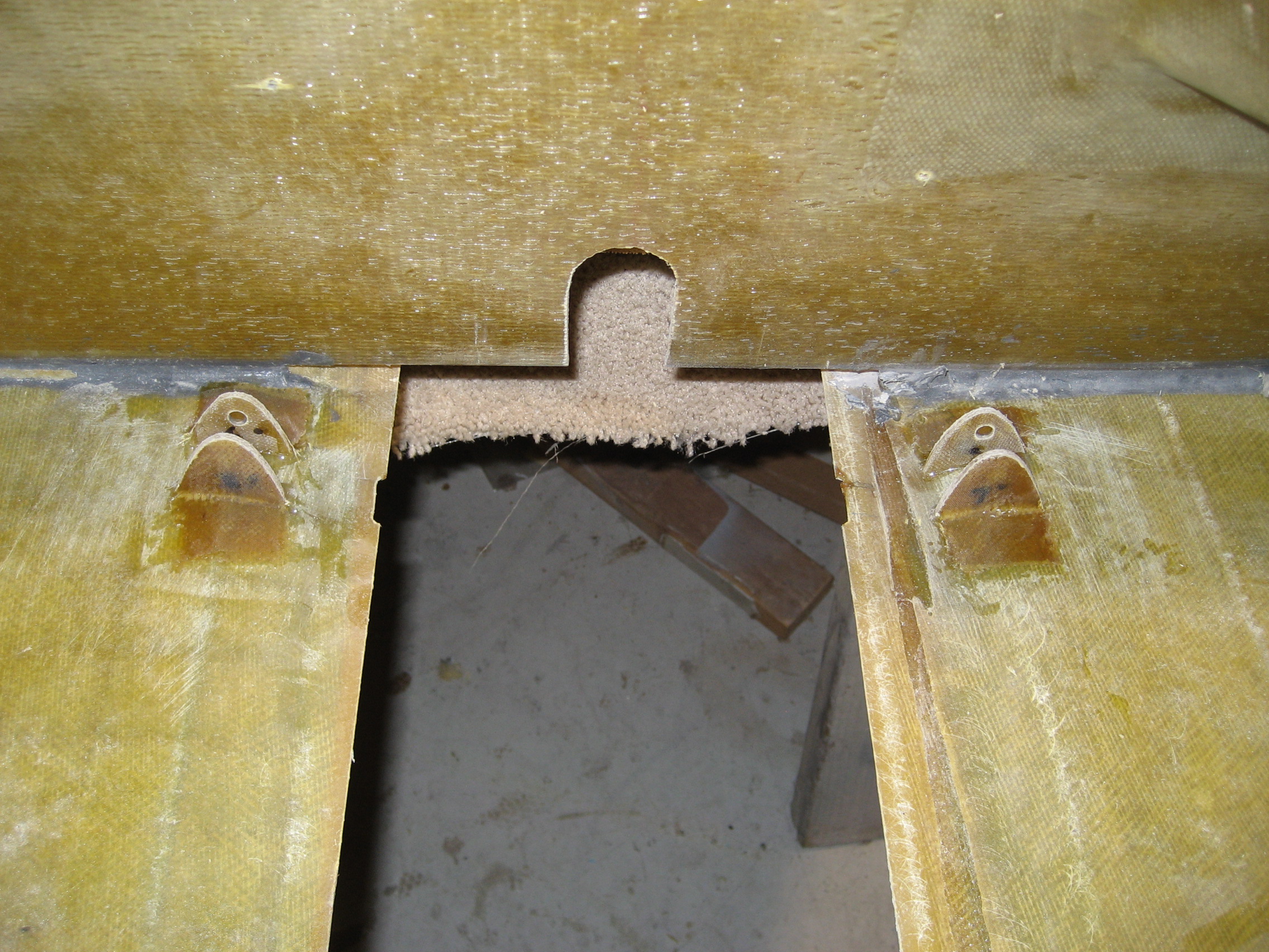
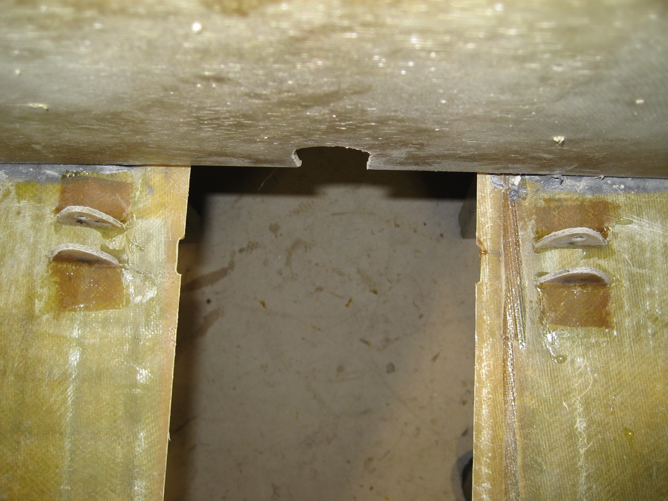
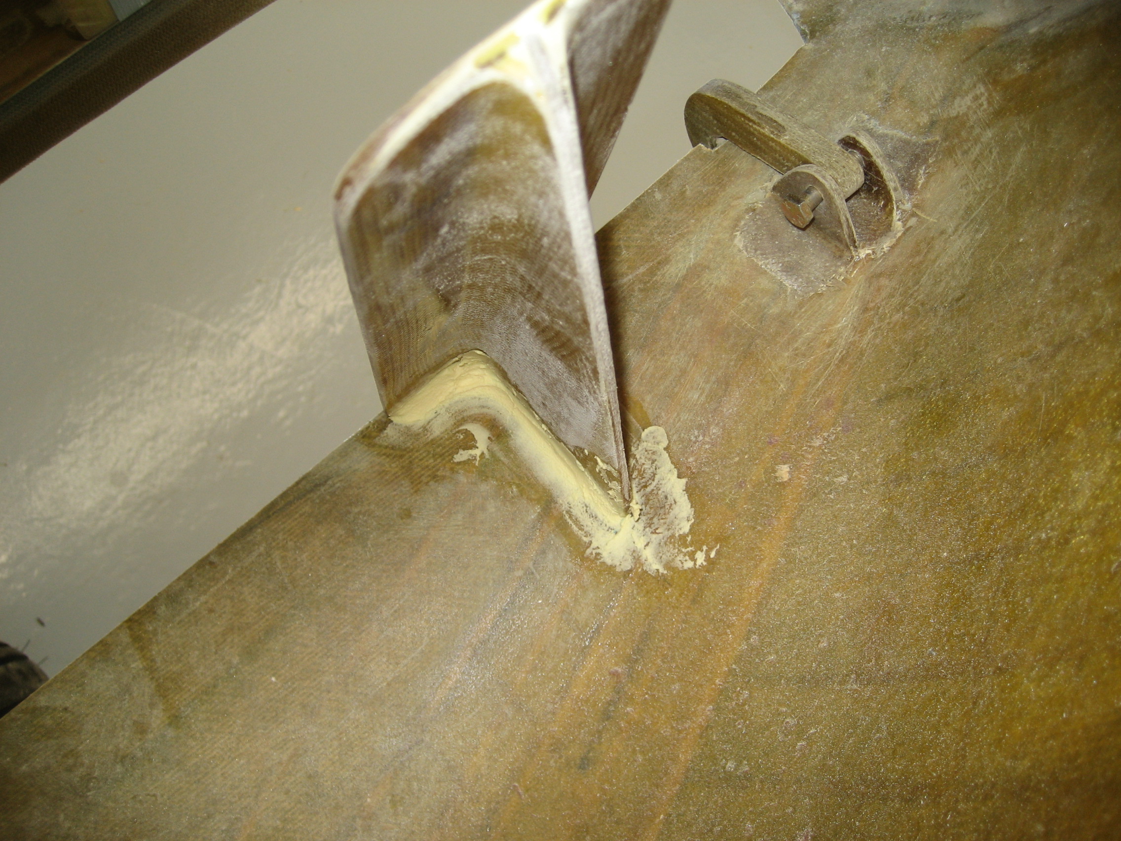
You’ll notice where the leg exits the fuselage, there’s an opening that’s a little bigger than the leg itself. When the gear is raised, that leg will swing up. But the hole isn’t big enough to allow that which means it has to be… bigger. But how big? Here’s my first dilemma: The book doesn’t really say. I was expecting a template that you would lay against the side and mark where to cut. Nope. No template. The book just says cut it, not how big. I’m a little nervous cutting when I don’t know where to cut so I fussed about this quite a bit. Down in Florida, I would have looked at another plane or asked someone and have been done. Instead, I reread the manual about 30 times, looked at pictures on other builders websites and read the manual again thinking I overlooked something. Finally, I just raised the leg and cut a little. And repeated this maybe 12 times until the leg would raise the correct amount.
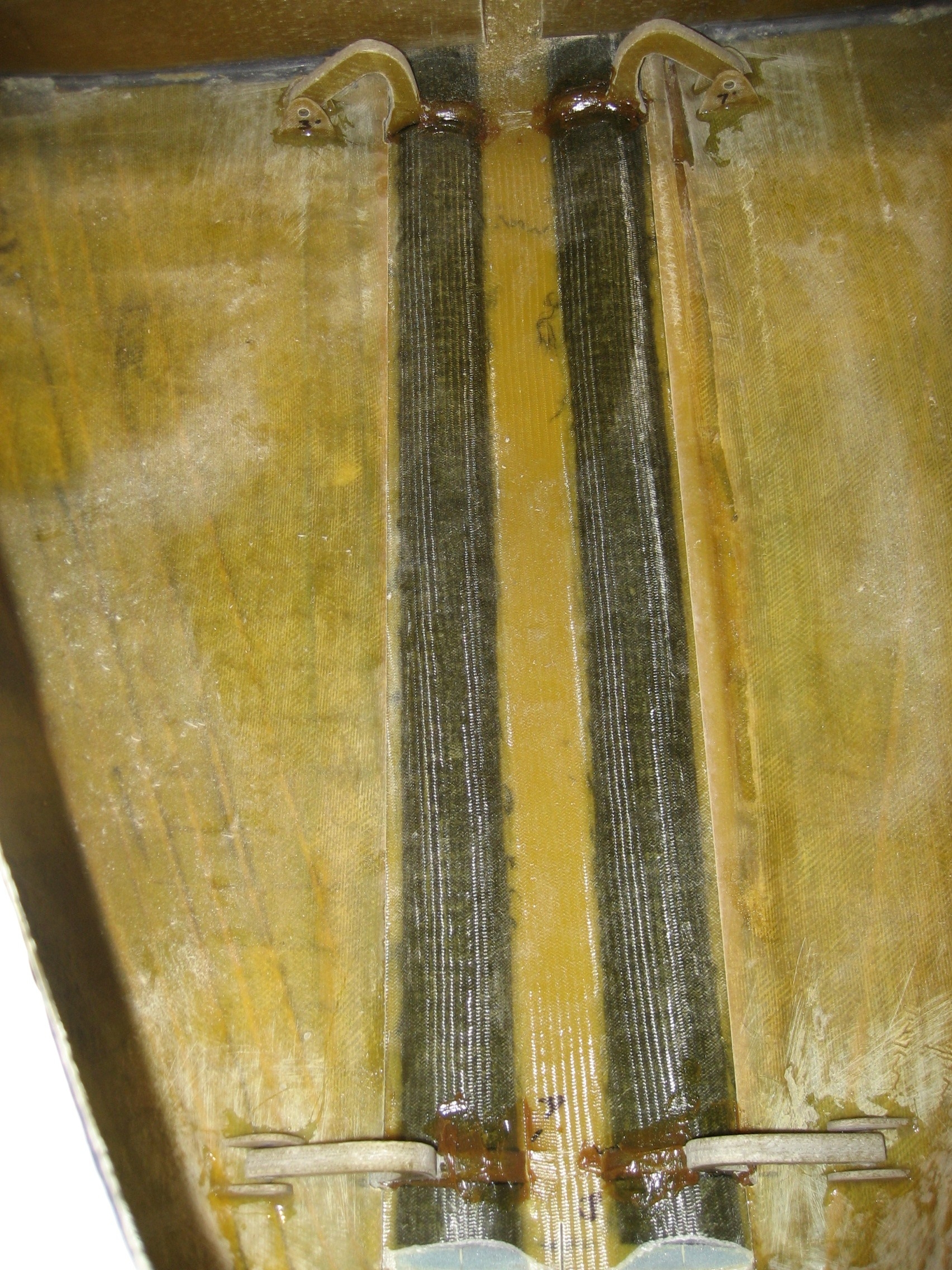
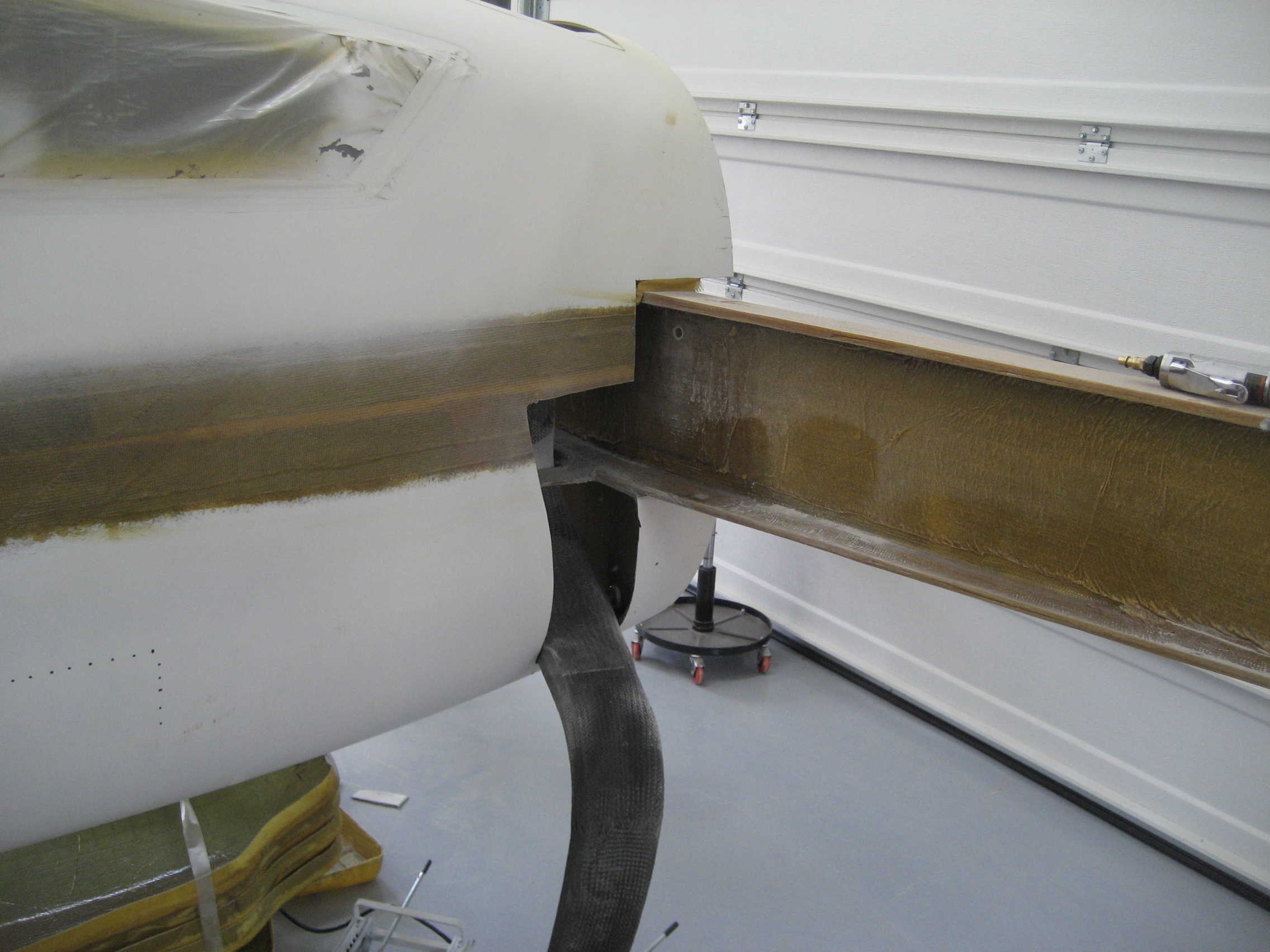
This the result of 2 hours of research and 45 minutes of cut, check, cut, check, cut check…

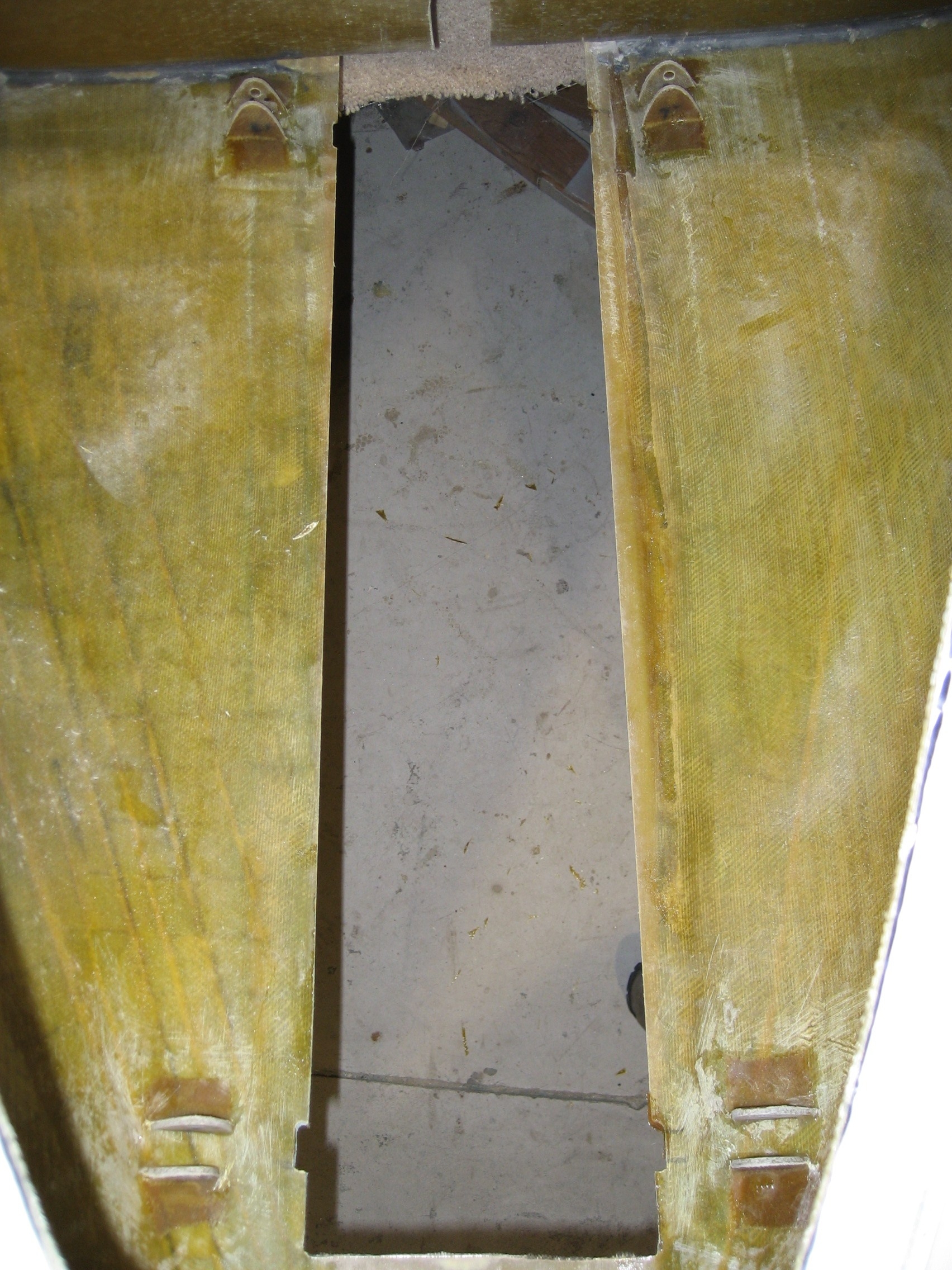
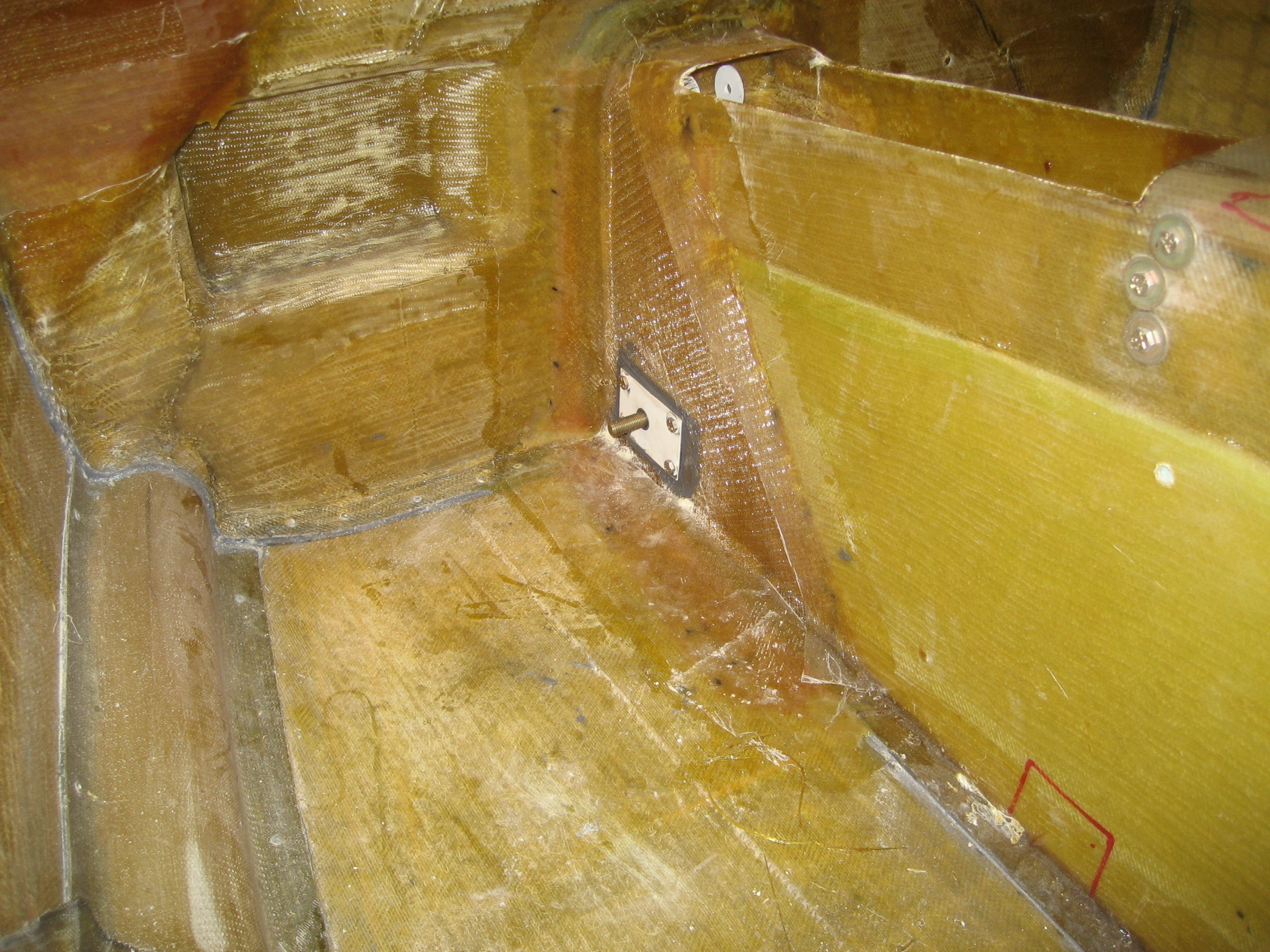
Gear leg up. (I removed the wheel to make it easier to work with.)

Once I knew how big the opening needed to be, the other side took about 15 minutes. This is where the time black hole is going to come from. The whole task is probably slated to take 30 minutes for both sides, but it took me over 3 hours.