7.4.3 Transverse Bulkhead Installation

This entry is part 26 of 39 in the series 07 - Landing Gear

After spending the last two weeks on the road, I didn’t get much building done. I did get some building related work done. Malcolm Collier of Hangar 18 fame is a professional builder who works with builders that don’t have much available time to build. His work is some of the finest and he has made some impressive innovations to the Velocity design. So after class was done on Friday, I flew over to Greenville, SC and hung out with Malcolm. I got some good ideas and some great tips. Then I had to spend the next week in New York City.

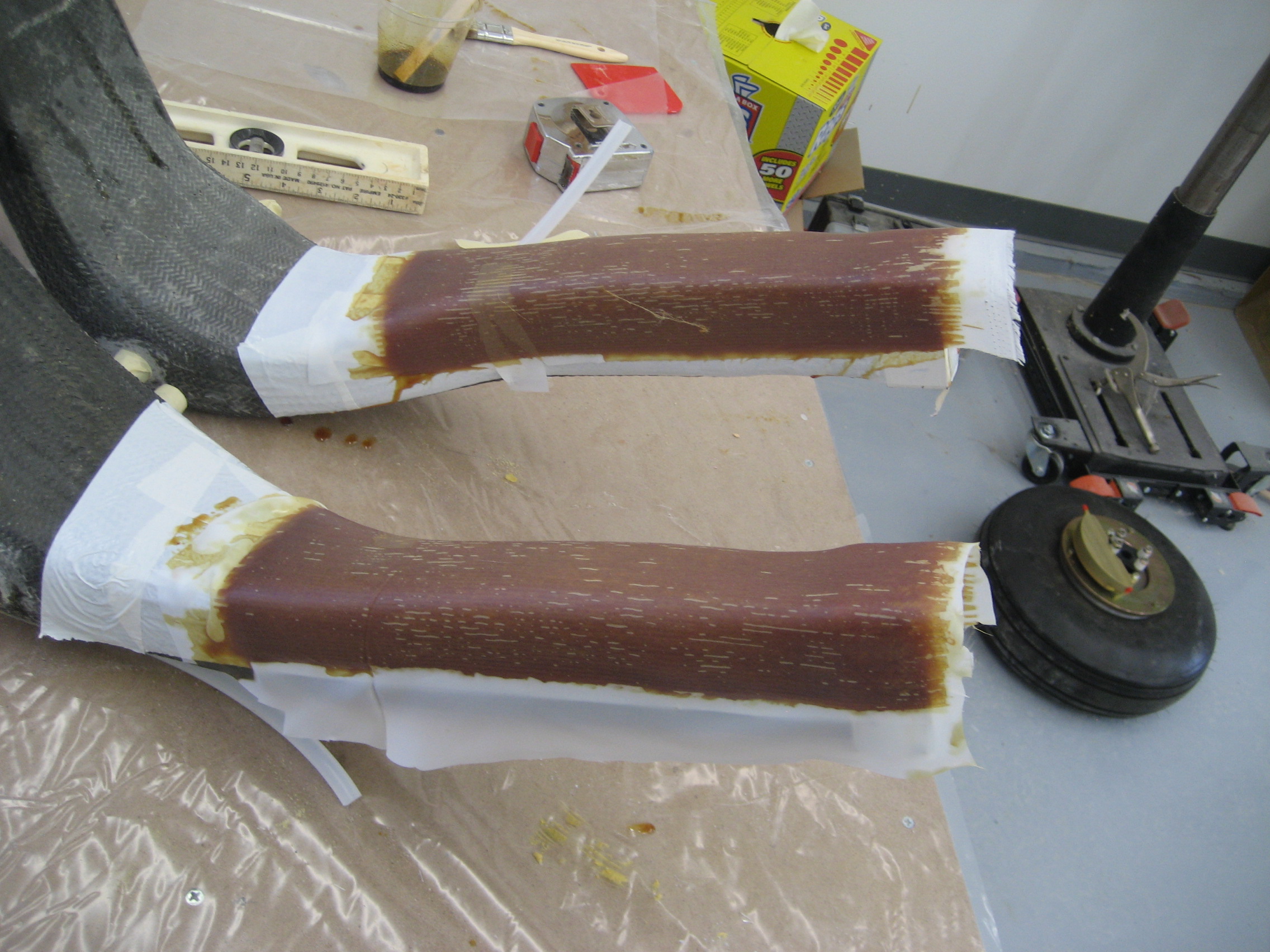
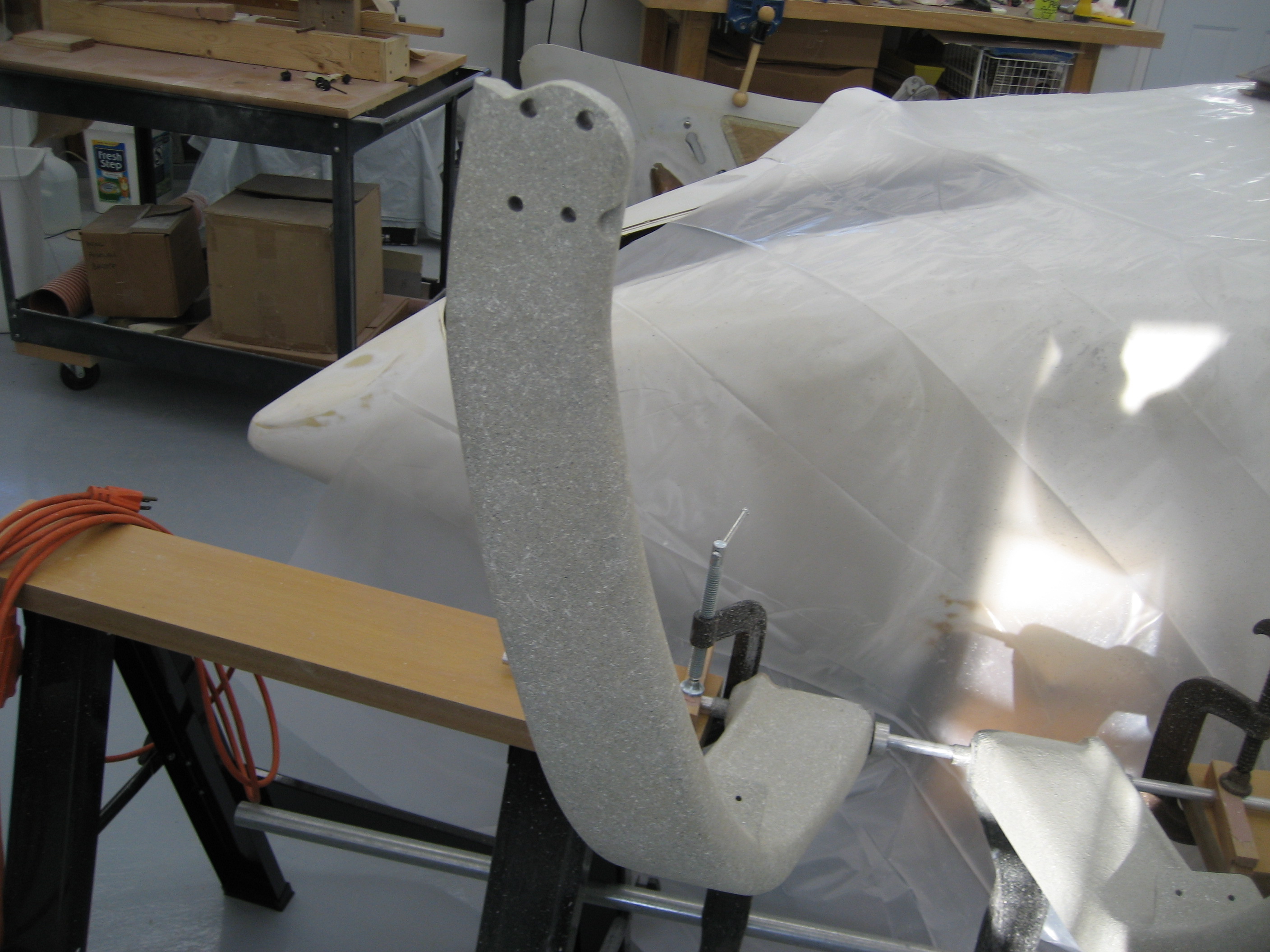
Once I got back from NYC, I resumed building. One of my tasks was getting the main gear positioned and aligned so I could permanently install the pivot bushings. Now consider that this airplane (when taking off and landing) is going to be moving down a runway at about 70 MPH. So the wheels should be in exactly the right location. Here’s another situation where the manual doesn’t go into a lot of detail.

The gear legs should be symmetrical and a line between the wheels should be perpendicular to the longitudinal axis. But how to determine that?

Here’s what I did. First, I leveled the plane front the rear and side to side. Then using a plumb-bob, I marked the centerline of the plane at the front and rear on the floor and drew a line between the two points. So now there’s a line on the floor from the front to the rear of the fuselage.

The vertical line to the centerline.

2008-05-12 1929 IMG_6897

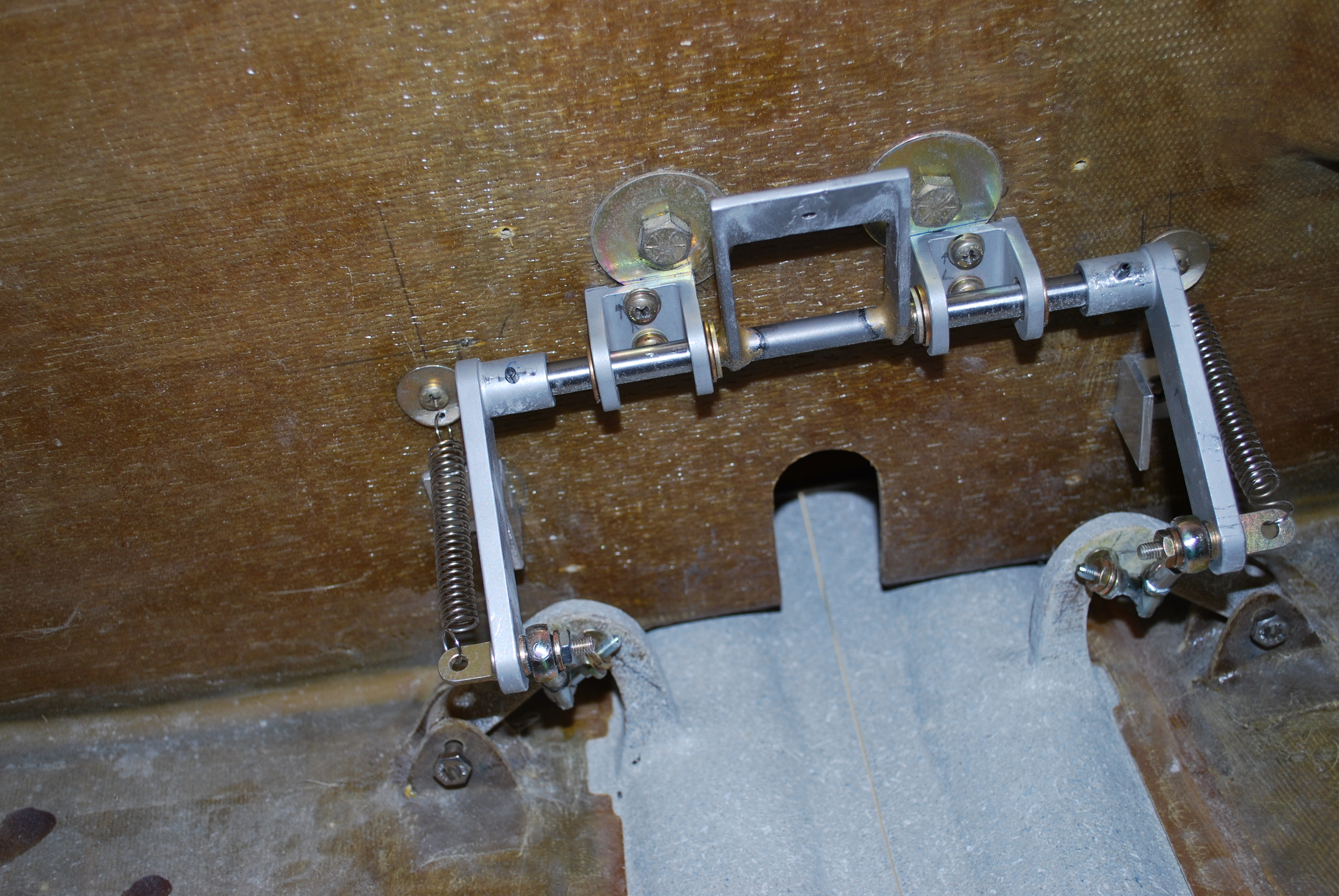
Next I ran a string from one of the wheel mounting holes on the right gear leg to the corresponding hole on the left gear leg. The I measured the distance between the two gear legs and put a mark on the string at the halfway point.

Then, using the plumb-bob from the mark, I adjusted the gear legs until the mark on the string was in the middle.

2008-05-12 1930 IMG_6898

  I actually put two marks on the string so I could easily see when the plumb-bob string was in the middle.

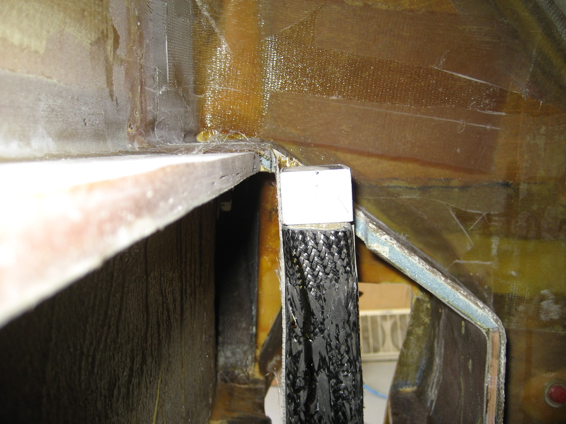
And here’s the plumb-bob on the floor. Dead-solid-perfect.

 2008-05-12 1930 IMG_6899

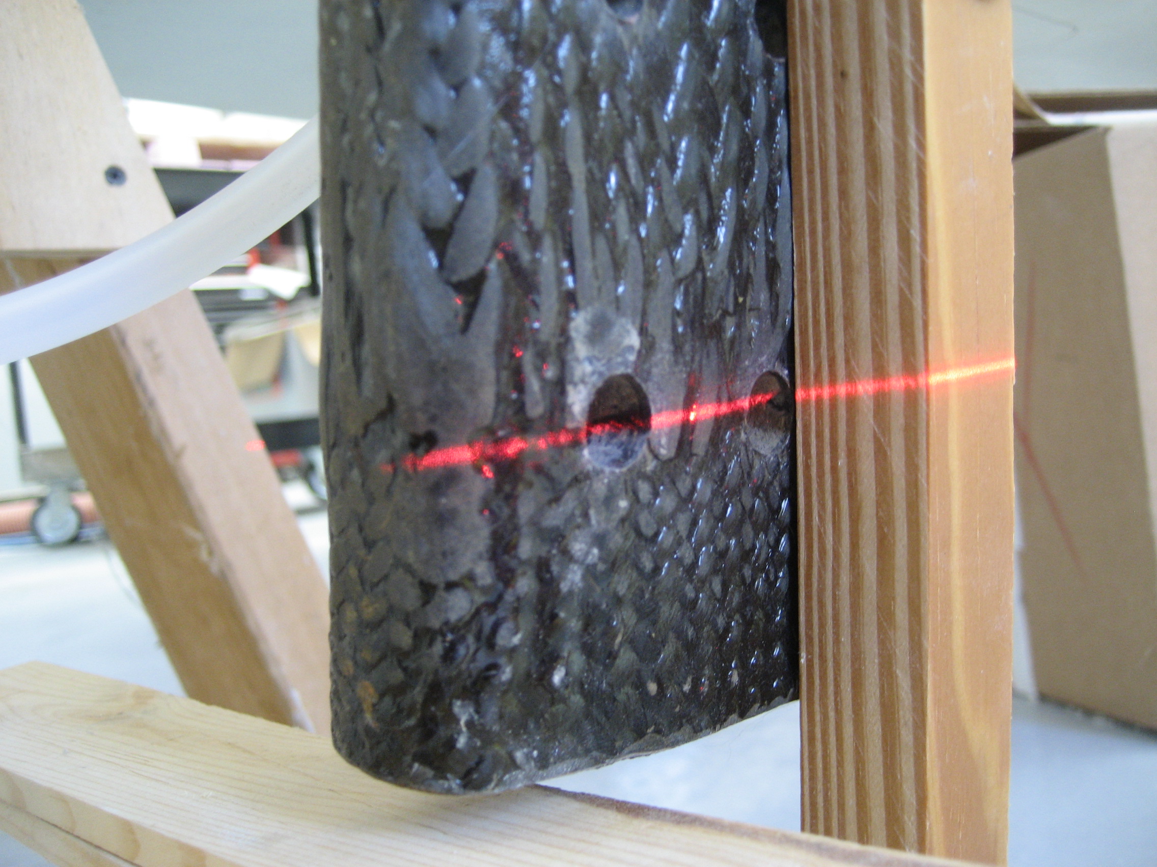
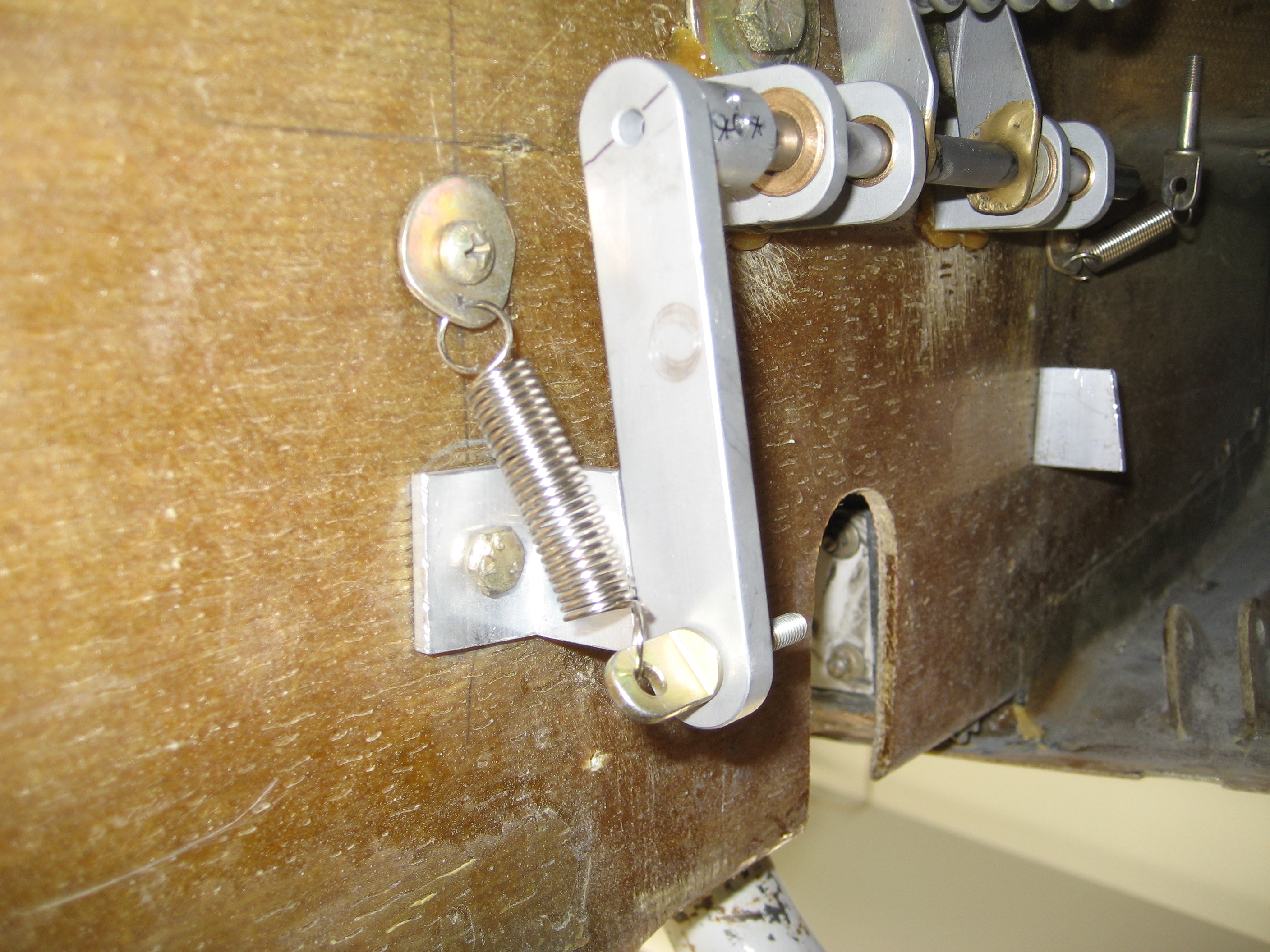
Next I had to get the gear legs positioned front to rear. For that, I used a laser. I pointed the laser through one of the wheel mounting holes on the gear leg so that it went through the same hole on the other leg.

From the right side, you can see some of the light from the laser on the bottom left hole.

 2008-05-12 1932 IMG_6901

 Then, I moved the the plumb-bob until it was hit by the laser.

Here’s the laser hitting the plumb-bob line.

 2008-05-12 1932 IMG_6902

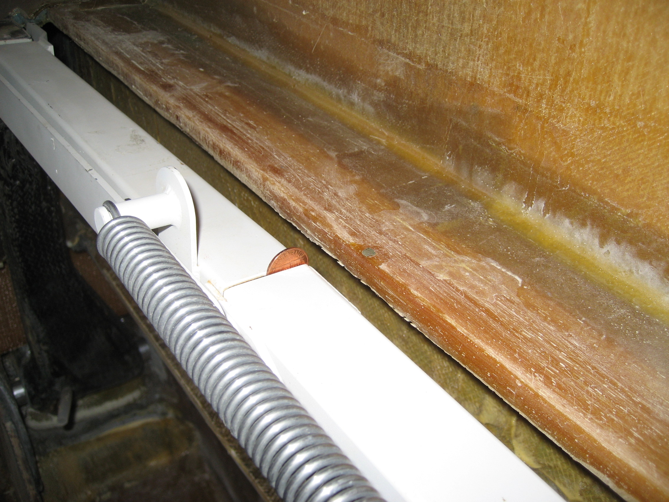
I then put a mark on the floor. I did this at a couple locations between the gear legs. Next I drew a line connecting the dots.

 2008-05-12 1933 IMG_6903

Checking the location of the line just to make sure nothing changed.

Finally, I just had to check that the centerline and the line between the gear legs was perpendicular and adjust if necessary.

Now the whole operation start to finish was about an hour but I must have spent half the day figuring out how to do it in the first place.

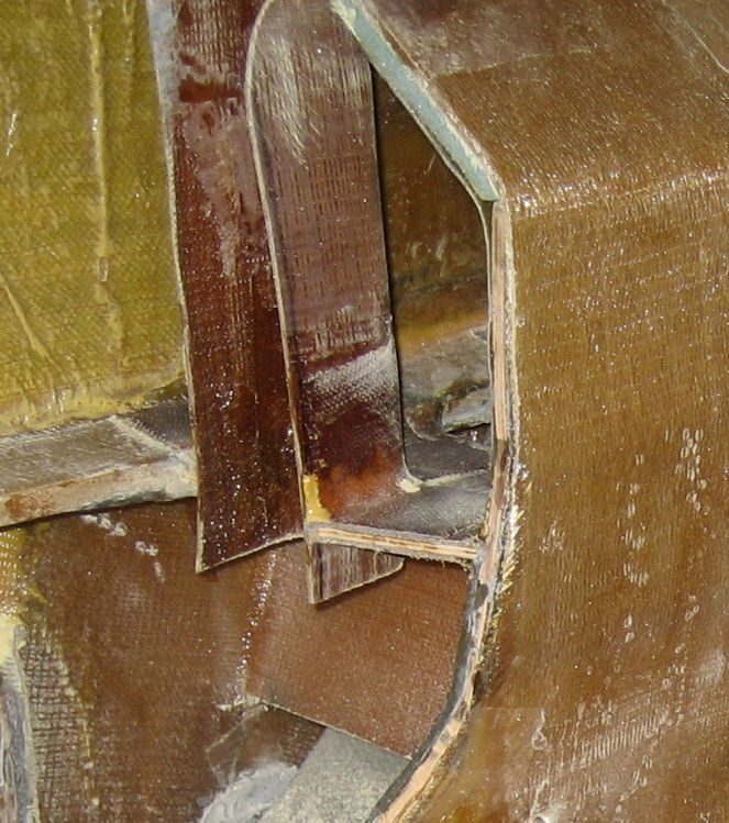
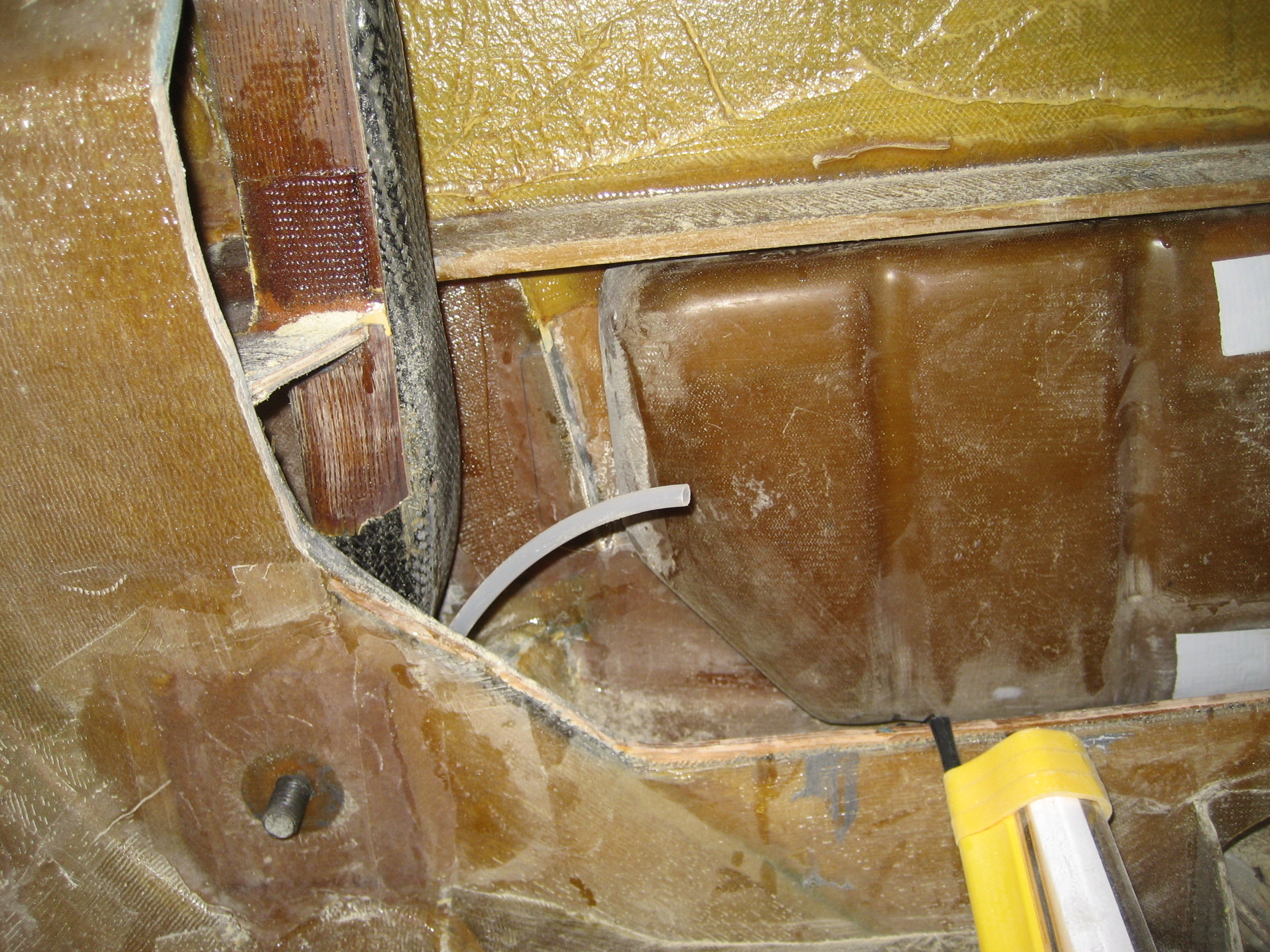
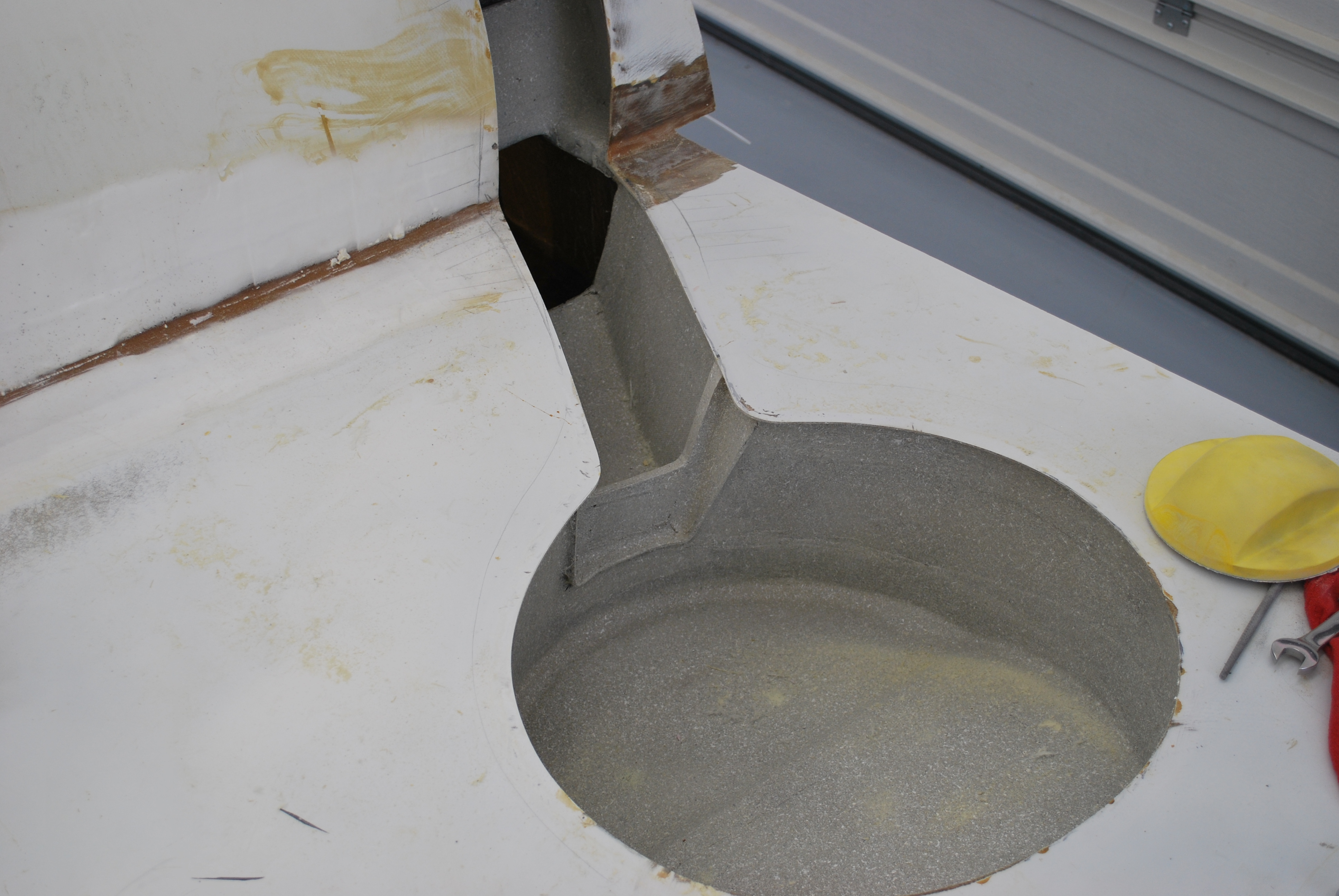
Next, I had to install and reinforce the transverse bulkhead. This relatively small piece connects the firewall to the main gear bulkhead. The plans call for the piece made to made from foam and covered with two layers of triax. I felt that using some plywood wouldn’t add much weight and would add strength. To determine the correct size, I used cardboard and trimmed it until it fit. Then I transferred the shape to a piece of plywood.

Plywood transverse bulkhead

 2008-05-15 1451 IMG_6915

Then I had to determine the shape of the triax fiberglass that would cover it. I used small pieces of posterboard and taped them together.

 This is the outside triax template.

 2008-05-15 1844 IMG_6917

Here’s the outside view of the transverse bulkhead with the layup in place.

 2008-05-18 0908 IMG_7111

Inside view on the transverse bulkhead.

2008-05-18 0908 IMG_7112

7.5 Main Gear Bushings

This entry is part 27 of 39 in the series 07 - Landing Gear

Once the transverse bulkheads were in and the layups were complete, it was time to permanently install the main gear bushings. The main landing gear is located between the firewall (at the very rear of the fuselage) and the main gear bulkhead. There is a hold drilled in the main gear leg where a steel sleeve is installed. A bolt goes through the two bulkheads and through the landing gear leg. The gear then pivots on this bolt which allows it to be raised to the retracted position. Where the bolt goes through the two bulkheads, an aluminum bushing is installed as a bearing point. Up until now, all these components were present, but not permanently installed.

Left main gear leg viewed from the inside. This is before the transverse bulkhead was installed. But you can see the gear leg, pivot bolt and forward bushing.

 2008-05-13 0726 IMG_6909

View from the inside showing the bolt and aluminum bushing temporarily installed.

 2008-05-13 0726 IMG_6910

My first order of business is to get the bushings in place. I removed the bolts, pulled the bushings, and coated the contact surfaces with structural adhesive. Then put everything back together and lightly tighten down the nuts. The manual says to also glue the sleeves in the gear leg at this time, but I was nervous that I wouldn’t get everything in position before things started setting up.

Once the bushing were in place, I pulled everything apart and used structural adhesive on the steel sleeves in the gear legs and put everything back together again. That’s when I discovered… a glitch.

Turns out when I tightened everything down in the previous step while the bushing were setting up, I didn’t get the nut very tight. Since the bolt head is on the outside and the nut is on the inside, I couldn’t hold a wrench on both. The result was that the nut wasn’t tightened enough. This resulted in an excessive space between the two bushings which allowed the gear leg to move front to rear. Since the sleeves had adhesive on them, I decided to position the gear leg as best I could and figure out what to do next.

I checked with the factory and they said I could either stuff some washers in or I could remove the bushings and put them back in. This was a bit of a surprise since I thought the adhesive was “permanent”. Turns out that if the adhesive is heated to the right temperature, it’s possible to remove the bushings. I removed the left gear again, put a soldering iron in the bushings for about 15 – 20 minutes and using a home-made press they popped right out. Then I cleaned up the openings. I hoped that I would be able to glue the bushings back in and be finished. But the steel sleeve wasn’t where I wanted it. In hindsight, I should have pulled the gear leg when I discovered the gap, removed the sleeve from the gear leg and cleaned off the uncured adhesive. 

So now I had to remove the sleeve. Which means sticking a soldering iron in the sleeve, waiting 20 – 30 minutes and with Steve’s help, we got the sleeve out.

Then I covered the bushings with adhesive and bolted everything back together. Once that cured, I removed the gear leg, put adhesive on the sleeve and put everything back together.

Once that one done, I had to put a two layer triax layup on the back of the firewall over the bushings and over the front of the main gear bulkhead over the bushings.

 All this took about a week. It should have a taken a couple hours. Pretty steep learning curve (not happy with this type of progress). 

Waiting for Steve to get the wrench on the inside nut.

IMG_2058

7.4.3 Transverse Bulkhead Installation

This entry is part 28 of 39 in the series 07 - Landing Gear

The final part of the transverse bulkhead installation was the layup just forward of the center spar. Fortunately, this one is done with BID instead of triax.

Looking in from the right side. On the left is the center spar and you can see where it exits the left side around the top-center of the picture.

2008-07-06 0713 IMG_7199

The BID layup starts at the bottom of the spar, goes forward, then up the main gear bulkhead, up the “slant bulkhead” (then out of the picture). 

Looking up at the bottom of the “slant bulkhead” and then you can (barely) see where it turns aft and stops at the top of the center spar. I had to use some clothes pins to hold the layup in place. Gravity, you know.

2008-07-06 0713 IMG_7198

7.6.2 Main Gear Sockets

This entry is part 29 of 39 in the series 07 - Landing Gear

The upper part of the gear legs (which are inside the fuselage) are supported fore and aft by sockets that they are held captive when the gear is extended. These sockets are made to be perfect fit to the upper gear leg by wrapping the area with duct tape and then applying 3 layers of triax.

Duct tape on the upper gear leg.

2009-04-08 1305 IMG_8530

Three layer of triax.

2009-04-08 1347 IMG_8532

Once cured, they are removed and then trimmed to the rough dimensions.

Currently, the only permanent aspects of the main landing gear are the pivot points which the gear legs pivot at and the over-center linkage which defines the distance between the tops of the two gear legs. So right now the over-center link can move left to right (which in turn lowers one leg while raising the other) about 1 inch. Once the sockets are in there will be no movement at all. So getting that position exact is critical.

This is the left upper gear leg and socket where it intersects the slant bulkhead. I’ve already created a notch in the bulkhead to accept the gear leg and socket.

2009-04-09 1555 IMG_85452009-04-09 1555 IMG_8544

Now the task is getting the two legs perfectly level. So here’s how I did it.

I raised and leveled the airplane, removed the axles from each leg. Then I leveled my laser level and shot the beam through the lower/rear hole in the gear leg.

Laser is level.

2009-04-11 1233 IMG_8552

Shooting from the outside at the right gear leg right through the center of the hole.

2009-04-11 1234 IMG_8554

And it’s a little low on the left side.

2009-04-11 1234 IMG_8555

Moving the gear legs a slight amount (lowering the right leg raises the left) and the beam is centered on both holes. Once I determined the method worked, I raised the gear and prepped the transverse and slant bulkheads for bonding in the sockets.

2009-04-12 0817 IMG_8569

Then the gear sockets are fitted on the gear legs and lowered gear with a penny is inserted into the over-center link. This keeps the upper arms spread slightly beyond where they are when the gear is down. This will prevent the gear from binding in the sockets when it’s lowered.

2009-04-11 1238 IMG_8563

Next I determined the correct position of the gear legs using the laser level and secured the position. Then I used structural adhesive/cabo to bond the sockets to the bulkheads. Once the adhesive has cured, the sockets to bulkhead is reinforced with a radius and BID on all sides.

2009-05-27 1647 IMG_8641a        2009-05-26 1058 IMG_8633

I will do the layups on the bottom when I flip the plane over.


7.7.1 Main Gear Leg UpStops

This entry is part 30 of 39 in the series 07 - Landing Gear

Next comes the main gear legs. Here’s the left side main gear leg in the “down and locked” position.
2009-10-11 0622 DSC_0363

And here is the leg in the retracted position
2009-10-21 0812 IMG_9451

The first thing I need to do is define the exact “up” position. So I put a 1/4″ piece of wood between the tire and the wheel well. Then I need to make that position permanent. The channel (or tunnel) that the gear leg sits in is supposed to be just a quarter inch above the leg. I say supposed to because mine is about 2 1/2″ (that will cost me a couple gallons of fuel). So I made a spacer out of leftover stock and glassed it in place. Then I wrapped a couple layers of duct tape on the gear leg, put a UNI/epoxy/cabo fill on top of the spacer and pushed the gear against the wood spacer. Let it set up over night and now I’ve got an “up stop”. I’ll clean this up later.

2009-10-21 0725 IMG_9450

This gets done to both sides.  


7.7.3 Main Gear Doors

This entry is part 31 of 39 in the series 07 - Landing Gear

When the main gear is retracted, the opening (most of it) is covered with a door. This door has to be cut to fit. Here’s the door before cutting. (The pencil line are reference lines for cutting )

2009-10-21 0813 IMG_9453

Here’s the door after cutting. The tongue depressors are glued to the door to keep it flush with the surface.

2009-10-30 0806 IMG_9482

I looked at that bottom opening and thought about a second door to close that off but decided it would too much work for not enough gain. 

Then the back side of the doors have to be strengthened/stiffened. This is done by gluing 1/4″ foam to the inside, beveling the edges and glassing over it with 2 layers of BID.

7.7.3 Main Gear Doors

This entry is part 32 of 39 in the series 07 - Landing Gear

The main gear doors are supported at the bottom by a piece of 1/8″ aluminum that gets cut so that it has four “fingers”. The aluminum supplied with the kit wasn’t as big as I would have liked, so I bought a larger piece and cut it to the correct shape. Then it has to be bent to conform with the inside of the door. This is a bit of a trick since you can’t really see very well where to bend and it’s a somewhat complex bend. Lots of trial and error. And it’s almost impossible to get it in the exact position. If the aluminum isn’t perfectly flat against the door, once you tighten down on a screw, it will deform the door and it won’t align.

Malcolm give me a bit of advice: Once it’s as close as you can get it, cover the plate with duct tape, apply a glob of epoxy/cab-o-sil and then lay the door down. Once it cures, you have a small “pad” that conforms perfectly to the support plate.Then a quick cleanup of the pads and you’re all set.

2009-11-23 1449 IMG_9564

Then holes are drilled through the door and the plate.

2009-11-15 1107 IMG_9544

Next, Nutplates are mounted.

2009-11-15 1109 IMG_9545

I don’t have a jig that determines the location of the holes for the nutplate, so I temporarily mount it and use it as the drill guide.

2009-11-15 1126 IMG_9546

Here’s another view:     

2009-11-23 1448 IMG_9560

That takes care of where the door attaches at the bottom. The factory says to attach the top of the door after the bend. Here’s the diagram from the manual:

2009-11-01 IMG_0381

But with the flexing of the gear leg, it seems that will cause cracks  to appear in the door where it has the 90 degree bend. So I beefed up the bend and put the mounting tab just before the bend.

This where I put the tab.

Another thing I did different is instead of using a piece of aluminum angle and screwing it to the door (which would leave a visible screw on the outside), I glassed a tab onto the inside of the door.

Here’s the tab on the gear leg.

2009-11-23 1448 IMG_9562

Another view of the inside of the door.

2009-11-23 1448 IMG_95632010-04-04 0657 IMG_0378

When you’re done trimming and mounting the door, it looks like this from the back.
2010-04-04 0650 IMG_0376

This is the top of the door from the side.
2009-11-26 1411 IMG_9575

That big honkin’ gap is there because when the gear comes down, the door would hit the fuselage and prevent the gear from fully extending if it was any longer. I guess the theory is no one will notice it’s there when the gear is down and the only time the gear will be up is where it’s in flight. But I’d know it’s there.

A couple emails to Malcolm revealed that I COULD have saved the extra to use a small door to cover the opening. But I couldn’t do that because I used the “sneak up on it” approach when I located the final position of the cut.

So I covered the side of the fuselage next to the gear door and laid out a few layers of triax and BID (so it would match the curvature of the fuselage). Then I cut it to fill the opening. To accomplish this, I used the tape-it-to-the-outside-and-shine-a-light-from-the-inside method to locate where to cut.

2009-11-23 IMG_9554

Then I cut and drilled a pair of hinges and did a dry fit. 
2009-11-23 1344 IMG_9555
Yep, it moves.
2009-11-23 1345 IMG_9558

I riveted the hinge to the mini-door and put nutplates on the side that would mount to the fuselage.

2010-04-04 IMG_0387 2010-04-04 IMG_0383
 Next I beveled the edge and built a flange so it would fit with the door.

2010-04-04 IMG_0382

Here’s how looks all installed and operational.

2010-04-04 IMG_03862010-04-04 IMG_03852010-04-04 IMG_0384

7.2 Nose Gear Installation (Door mechanism)

This entry is part 1 of 39 in the series 07 - Landing Gear

This is an area that’s been bugging me since day 1. The main gear doors a attached to the gear legs. But the nose doors are hinged. They are brought up by means of a rather complicated hydraulic system. Here’s a picture of a completed plane.

This picture is looking aft at the canard bulkhead. The greenish looking pipe going down is the nose gear leg. The opening at the bottom is the space that the nose gear comes through when it retracts. You can see the rear hinge arms of the nose gear doors (they’re white). Those doors are closed by a hydraulic cylinder (gold at the top center partially behind the large red flexible duct) which pulls up on a pair of arms that extend down to the door hinges. The hydraulic cylinder is activated by a switch (off to the right near the bottom of the cylinder) that gets triggered when the nose gear is up.

I’ve seen a couple other builders that used this method. After some investigation, I found the guy who builds these.

I asked the builder who came up with this if he could build one for me. But his fabrication guy was unavailable. So Malcolm told me he had built one that it’s in a plane nearby. A call to Terry Miles had me stopping by to take some pictures and measurements.

Same view as the previous picture but with the Hangar 18 mechanism.

The spring is so that when the gear bounces a little while in the up position, the doors will stay closed.

Some fabrication I can do. But I’m not a welder and I don’t have a milling machine. So Lynn, my current A&P put me touch with a guy who put me in touch with a guy who does metal work. I sent him my drawings and measurements. In return, he sent me:

Here are those parts installed.

Now I have to get the linkage and spring so I can drill for the pins to fix the arms in place.

7.7.1 Main Gear Legs (Painting)

This entry is part 33 of 39 in the series 07 - Landing Gear

The main gear legs don’t have to be painted. Neither do the gear wells. But it would look so much nicer if it’s not bare fiberglass. The gear legs are going to be hit by small rocks kicked up be the tires during takeoff and landing. So regular paint would look pretty bad after just a couple takeoffs and landings. Malcolm suggested Zolatone paint. It’s “splatter” type of finish that takes abuse without showing and doesn’t require prefect finishing prior to painting.

So I ordered a quart and started shooting. This stuff is a pain to shoot! If my gun had a larger nozzle, it would probably be easier. As it was, every now and then the nozzle would get hopelessly clogged and I would have to clean it out. What could have taken 15 minutes with the correct nozzle took about 90 minutes.

Gear well:
2010-02-11 0836 IMG_0113

Closeup
2010-02-11 0836 IMG_0114

Gear leg
2010-02-11 0837 IMG_0115

Finished and reassembled.

  2010-03-05 0151 DSC_207 2010-03-05 0151 DSC_208