
In preparation for mounting the brake assembly to the wheels, I had
to remove the wheels from their axles. When I did, I received a very
unpleasant surprise. It would seem that when the wheels were mounted
on the axle at the factory, the bearings weren’t packed with grease.
The result was this:
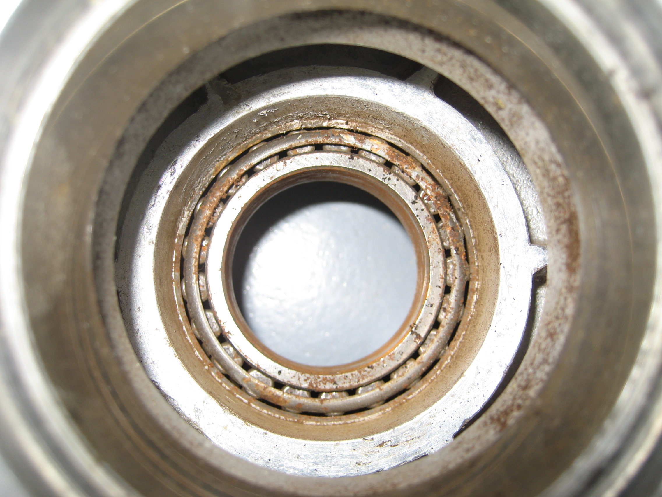
and this:

Only one of the races was rusted so that and all four bearings had to be replaced.
Blog Archives
8.1 Matco Brake Upgrade
During the build, I learn volumes from other builders. Through their websites (like this one), email, message boards and fly-ins like Oshkosh and Sun-n-Fun. One of the things I hear repeatedly is that the Matco brakes that come with the kit are awful. Both from a building standpoint (a pain to work with and around) and more importantly from a functional aspect. It appears that a common complaint is that the brakes feel mushy and brake fade is almost a certainty during heavy braking.
After hearing these stories I discovered that Velocity offers an upgraded braking systems from a different manufacture. Cleveland brakes are easier to work with and offer much better braking. But when I checked with Velocity, I learned since I had already taken delivery, I couldn’t exchange the brakes and that I would effectively have to purchase them outright.
Arrgh!
So I did some research. FAR (Federal Aviation Regulation) 23.735 states:
- Brakes must be provided. The landing brake kinetic energy capacity rating of each main wheel brake assembly must not be less than the kinetic energy absorption requirements determined under either of the following methods:
a. The brake kinetic energy absorption requirements must be based on a conservative rational analysis of the sequence of events expected during landing at the design landing weight.
b. Instead of a rational analysis, the kinetic energy absorption requirements for each main wheel brake assembly may be derived from the following formula:

where–
KE = Kinetic energy per wheel (ft.-lb.);
W = Design landing weight (lb.);
V = Airplane speed in knots. V must be not less than Vs √, the poweroff stalling speed of the airplane at sea level, at the design landing weight, and in the landing configuration; and
N = Number of main wheels with brakes.
Got that? 🙂
The brakes that I have are Matco model W600XT’s which have a “KE” rating of 337,932 ft.-lb.
I haven’t been able to find the rating of the Cleveland brakes, but they’re the same brakes used on a Cessna 210. Now the Cessna 210 is BIG airplane. Six seats with a gross weight of 3,800 pounds. By comparison, the Velocity XL-RG has four seats with a gross weight of 3,000 pounds.
Those brakes on a Velocity would clearly be enough, right? Not so fast… literally.
Reviewing the formula, notice the “V”. That’s the speed of the plane at landing.
Plugging the Cessna 210 specifications into the formula reveals a KE requirement of 292,996. Which means that you could use the Matco’s on a Cessna 210 with a 13% margin. So why are the Cleveland’s so much better at stopping? I suspect that the Cleveland brakes are rated a bit higher than the Matco’s. Probably around 350,000 ft.-lb.
So then I used the Velocity numbers in the formula. What I discovered is a KE requirement of…. drumroll please. 348,863 ft.-lb.
For me, this is a problem. Because the Velocity lands at 75 knots instead of 57 knots like the Cessna 210, the amount of additional braking energy required is significant. The Matco W600XT brakes are rated at only 337,932 ft.-lb. This explains the mushy brake complaints and fade after heavy braking. As far as I’m concerned, this changes the Matco-Cleveland issue from an “optional upgrade” to an “absolute necessity”. But the upgrade (which by my estimate would bring just within specs) was going to cost about $1,000.
So I did more research. I heard rumors of what I can only describe as a mythical Matco brake rated at 450,000 ft.-lb. I could find no reference to this “super brake” anywhere. No other builders have them, and no one has heard of it.
So I took a wild shot in the dark. I called Matco. 🙂
I was connected to an engineer and I explained my situation. He seemed… concerned that I was running W600XT’s on a Velocity. He said that I need W600XTE High Energy brakes rated at… wait for it… 450,000 ft.-lb.
So I asked how much they cost. He said “You’ve got 600XT’s?” I told him I did and he said that I could just replace a couple parts to convert the 600XT to a 600XTE (High Energy). “How much is that going to cost?” I asked, bracing for the response. “About $300” he replied. I ordered them on the spot.
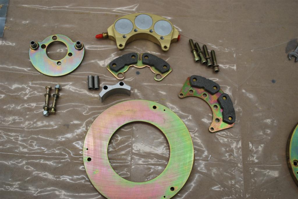
Here’s the parts list:
WHLD6HE – High Energy Disc (2 required) $96.62
WHLBSP600XT-1 – Spacer (2 required) $39.29
WHLBSP6-1 – Spacer (4 required) $4.95
MSC.31-17×1.75HHBOLT – Bolt (8 required) $1.60
WHLBSP600-1 – Spacer (4 required) $4.95
WHLLM29700LA – Roller Bearing (4 required) $21.08
MSCAN4-21A – Bolt (4 required) $.60
MSCNL8 – Washer (8 required) $.69
It actually came to $416 (he initially forgot about the bearings), but still a bargain for better stopping power.
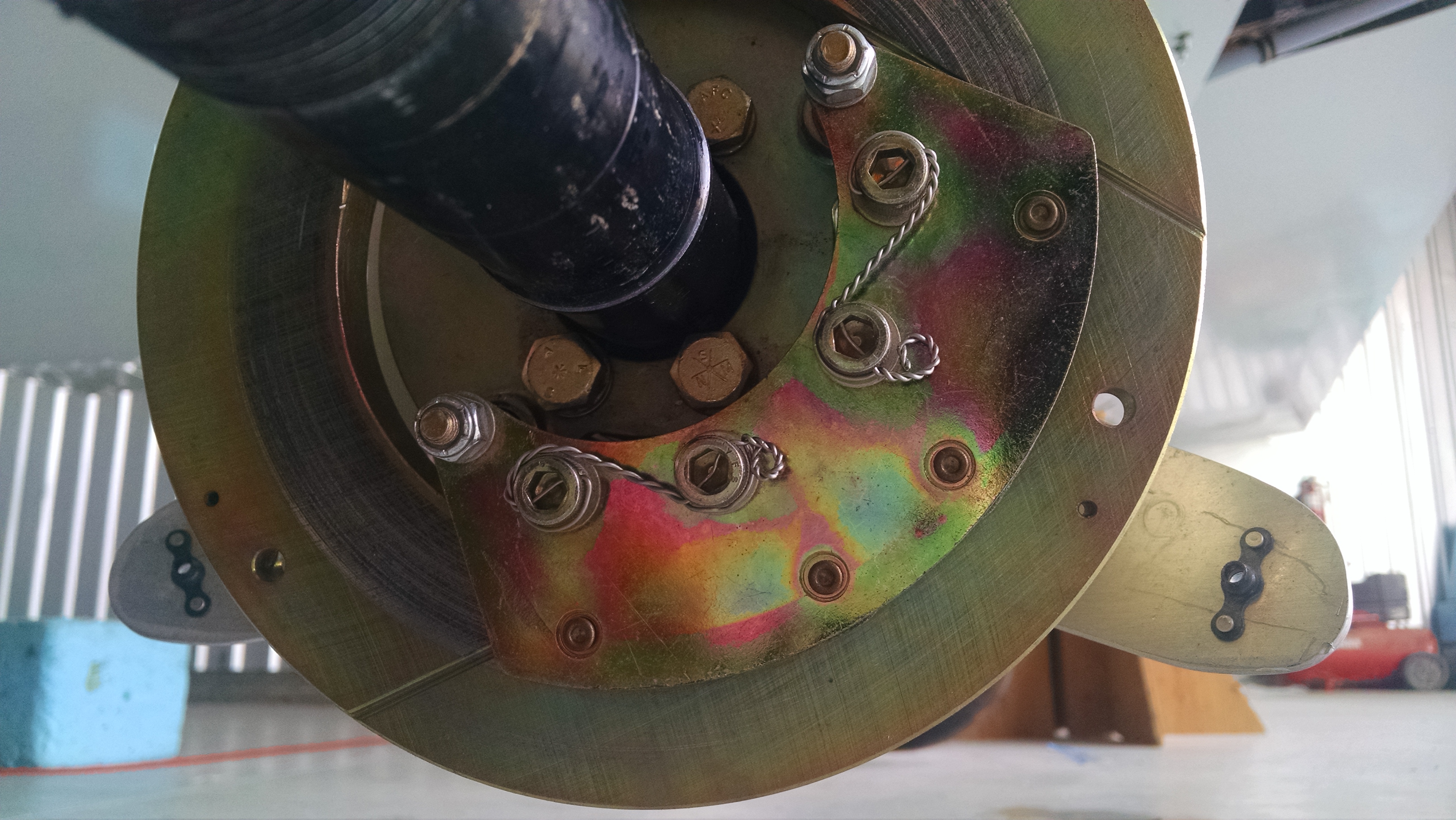
Here are the inside and outside view of the current brake system


Here are all the tools that I used:

First I removed the two nuts and bolts that hold the torque plate in position.

You can remove the torque plate at this point.
Next the four hex screws that hold the calipers in place.

Here it is disassembled.
Then it’s just putting it back together in the reverse order while substituting the new parts for the old.
Here’s the end result. New W600XTE on the left.

In the upper right corner, you’ll notice a bag of bolts and washers. These are supposed to replace the caliper retainer bolts/washers. Originally, these are safety wired. Instead of allen-head screws that are safety wired, they sent me regular hex head bolts with some fancy locking washers. My guess is that when you remove these bolts the washers will have to be replaced. I’m going to call Matco to see if I can still use the old screws with safety wire. Otherwise, I’ll order a bunch of these washers.
The primary difference is the disc. It’s thicker and it has three angled grooves cut into the face. All the other parts simply allow the thicker disc.
Here’s a close up of the old and new disc.

Now this isn’t going to make servicing the wheels and brakes any easier. But I’ll be able to stop. 🙂
I’m still a ways off from finding out how well they stop but now I’m much more confident that I will stop.
8.1.1 Main Gear Wheels and Axles
This is a fairly big job. Once I got the brakes upgraded, I need to get the wheels and brakes mounted to the gear legs. The first challenge is that the gear leg needs to be cut.
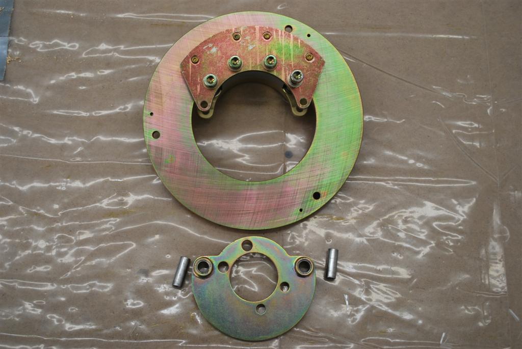
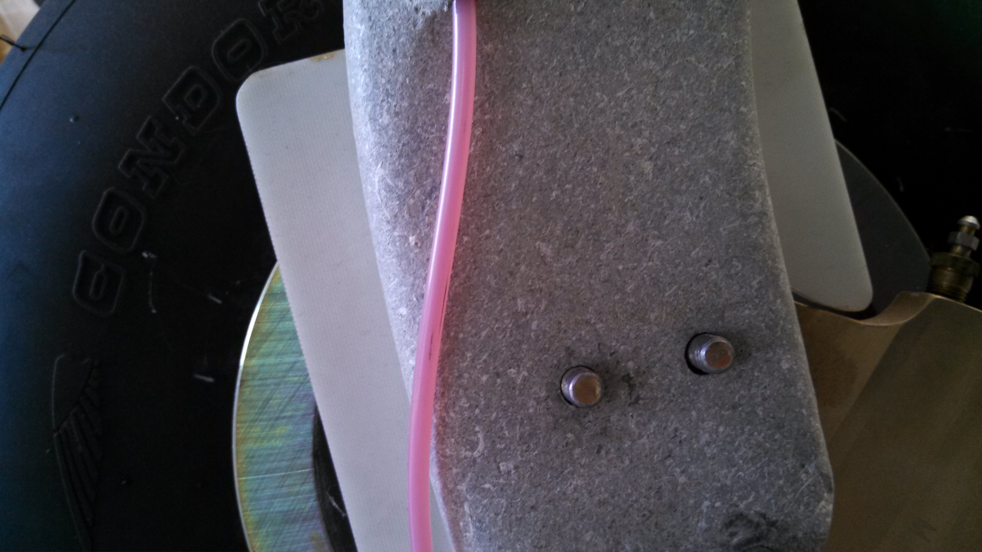
Here’s the bottom of the gear leg and the four holes that are used to bolt the axle and brake torque plate to the gear leg.

This is the gear leg side of the axle mounting flange.

Notice where the caliper is? Well not only does the gear leg have to be cut, it’s going to be cut REALLY close to those bottom holes. So the first thing that I need to figure out EXACTLY where to make that cut. I don’t want it any shorter than possible. To determine the cut location, I made a template from some masonite. It was basically trial and error but eventually I ended up with this.

Because black ink won’t show up on the gear leg, I applied some masking tape.

Then position the template with the four bolts.

And trace.

The next challenge was to make the cut. If the gear leg was made out of wood, I’d leave the template on and use a router. But the material used in the gear leg is TOUGH. So that’s out of the question. I would probably ruin two $25 bandsaw blades cutting the two gear legs. Malcolm at Hangar 18 suggested using Permagrit blades in a jjigsaw. About $3 for a blade and it went through the gear leg like butter.

The heat generated by the brakes could cause the gear leg to weaken over time. To prevent this a heat shield is used. The factory ships a “phelolic” sheet with the kit that is placed between the gear leg and the axle/brake/wheel assembly. I elected to upgrade to a material called “Garolite”. This has much better heat shielding properties. It’s pricey (about $50 for a sheet) and the minimum size is enough to make four shields. But after I made mine, I sold the remaining stock to another builder so it only cost $25 for both gear legs. In aviation money, that’s a bargain!

To cut the material, I used my template again. First I clamped to the Garolite to the template and marked it.

Then I cut the Garolite with the jigsaw and cleaned it up with a carbide burr.

To allow movement of the brake caliper through it’s entire range, I had to create a notch for the upper torque plate mounting bolt.


Once I mounted everything, I had to disassemble everything and grind off material from the gear leg here and there until all the parts had necessary clearance. I probably mounted and removed the brakes over a dozen times.
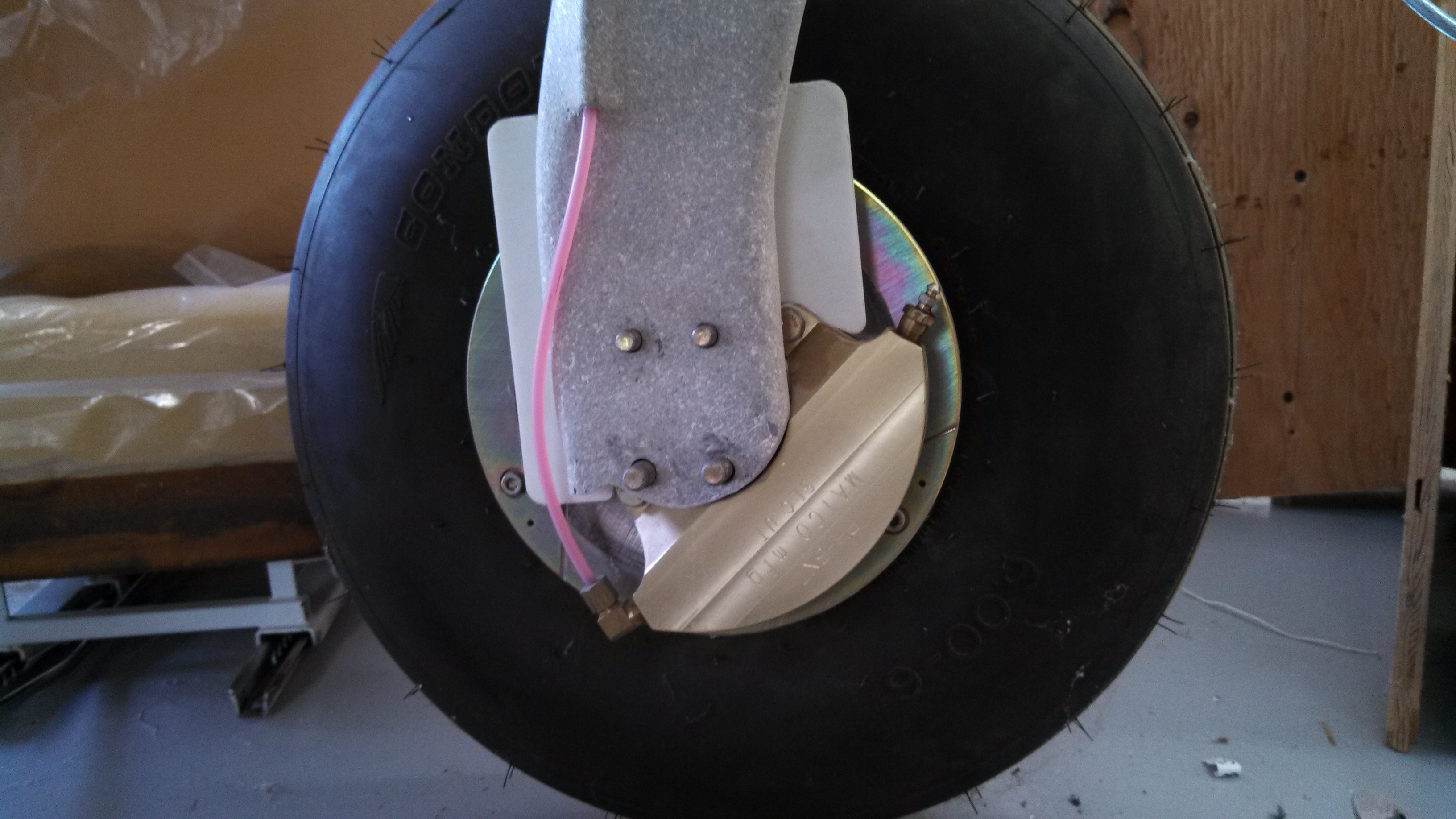
Here’s the end result.


8.99 Brake line protection
One of the things Malcolm does is to protect the brake lines between the gear leg and the caliper with some stainless steel spring. But we forgot that when we connected the brake lines. So until I need to disconnect them, I’ll have to get by with spiral wrap.
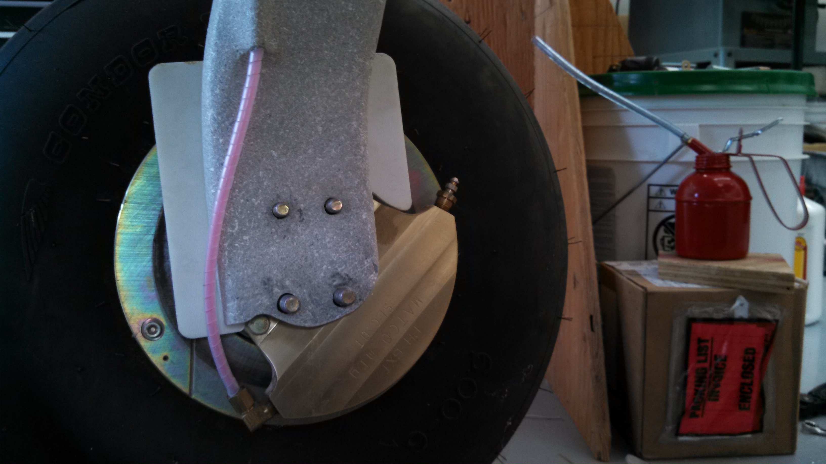
Here’s the existing brake line.
A closeup
Closeup after wrapping with spiral wrap

The finished brake line.
8.1.2 Parking Brake Micro Switch
Since I’ve installed a parking brake and I have a “Parking Brake Engaged” warning light, I need a way to activate the warning light when the parking brake is engaged.
I had been trying to figure out where to mount the switch. But then once the avionics shelf brackets were mounted, it became pretty obvious that was the place.
So first I had to make a mounting bracket.

Then drill a hole in the avionics shelf bracket and mount the bracket and micro switch.

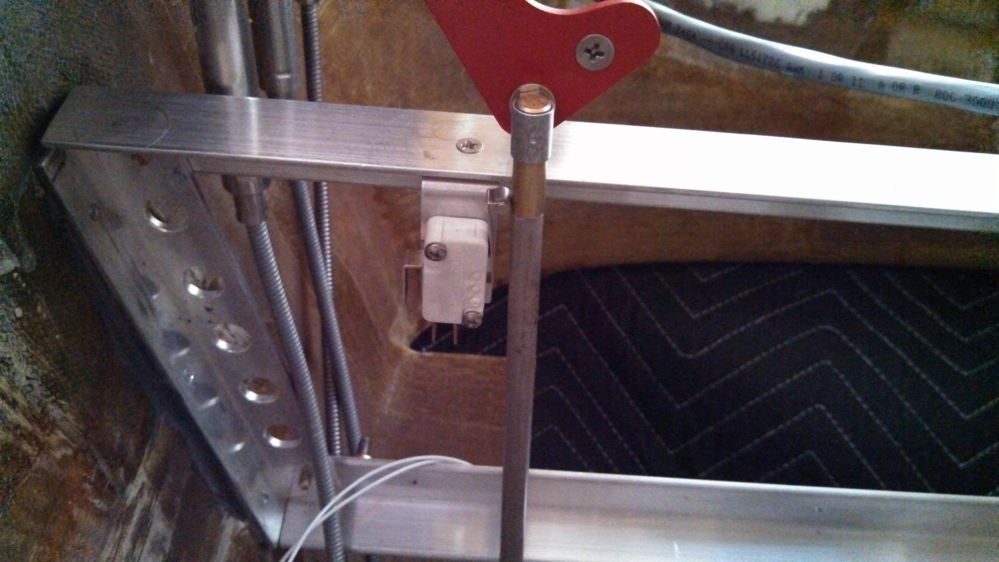
When the parking brake handle is in the “normal” position, the switch is open. Pull the handle a bit and the switch closes and the warning light comes on.
8.1.2 Main Wheel Alignment
This is definitely a two-person job.
The wheels on the main landing gear have to be aligned. Simply put, they need to point slightly in toward the nose. Here’s the procedure:
- With the plane on the ground, roll it backward 15′ and then forward 15′.
- Using a plumb-bob, define the centerline of the fuselage by marking a point on the floor at the nose and the center of the prop at the rear.
- Measure out from the centerline to the outside of the left and right wheels.
- Measure out from the centerline at the nose left and right the distance obtained from the previous step.
- Using a wicked-ass long I-Beam, place it against the tire and see what distance it is from the centerline at the nose. It should be 1″ (closer to the nose) than the measurement from step 2.
To change the toe-in, shims are placed between the axle mounts at the front or rear depending on whether you want to move the line in or out. And you have to jack the plane up to do this. Which means when you put it back on the ground, you’ve got to do the 15′ back and forth rolling thing.
Malcolm swore that the geometry of the landing gear is such that there won’t be any difference in the measurements with the plane on the ground or on jacks. I didn’t buy that. So we tested it. Measured the alignment on the ground and then jacked up with the wheels off the ground. Exactly the same. That’s going to save a ton of time!
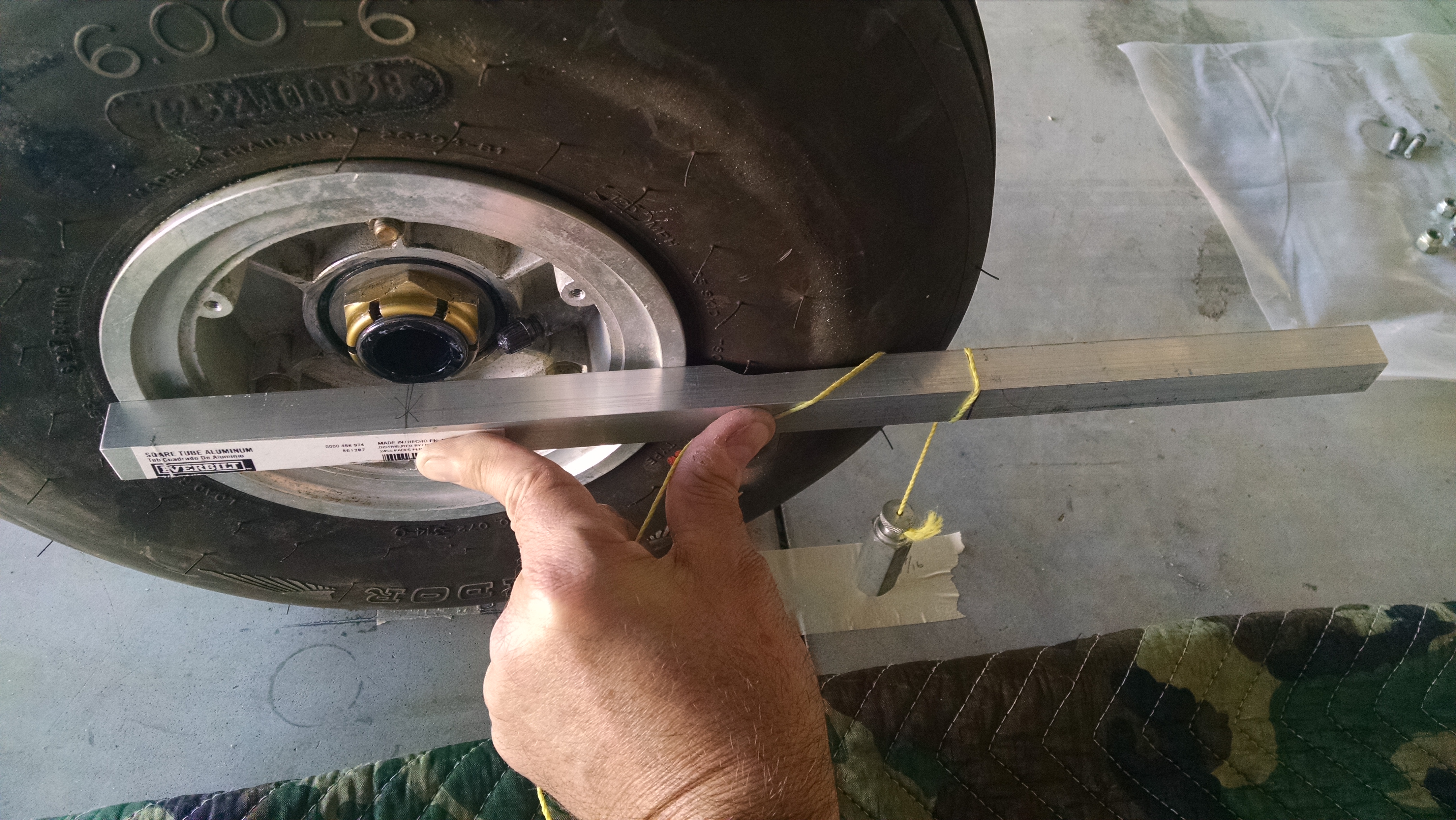
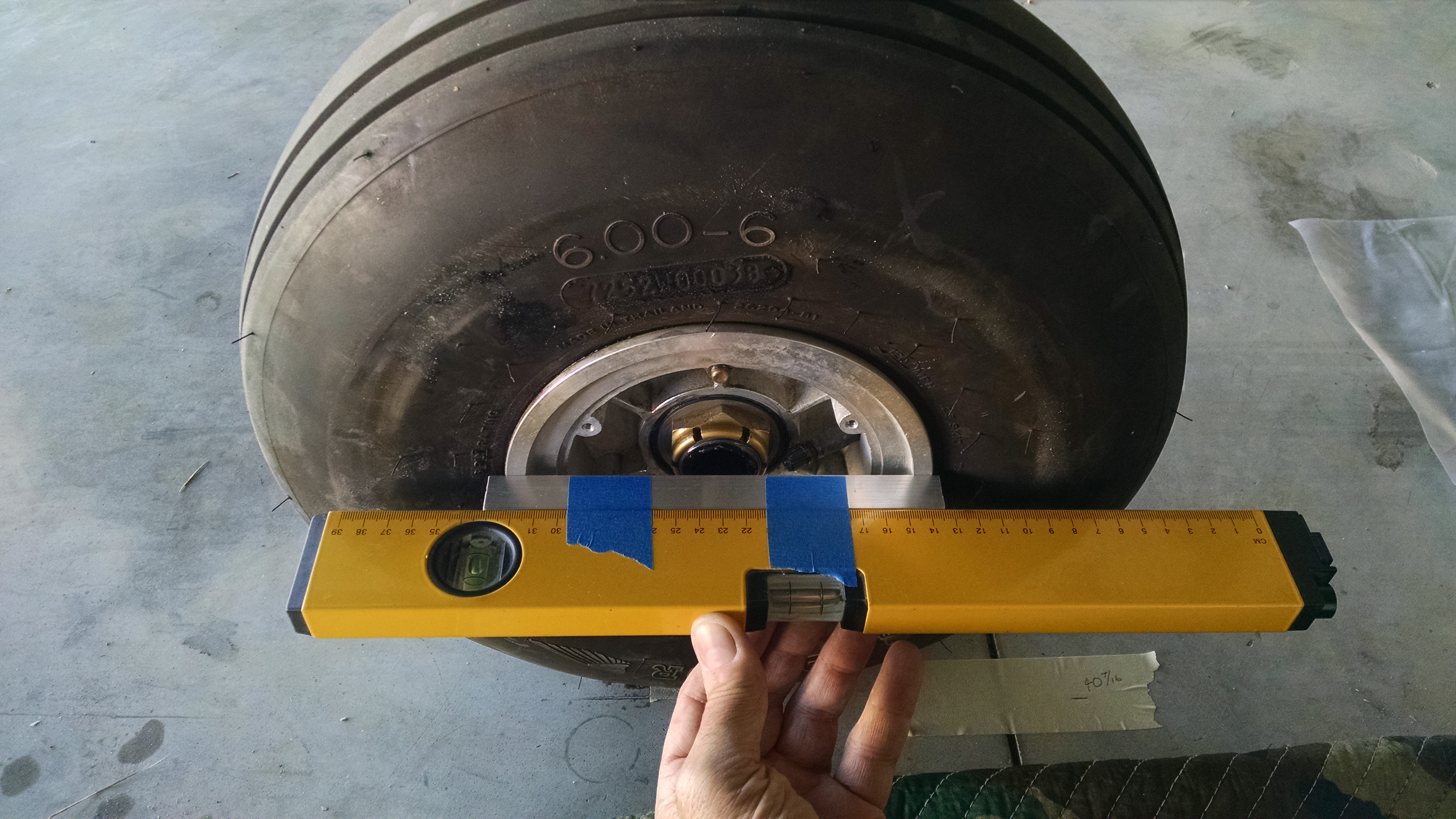
The next deviation is to not trust the tire being perfect. Instead of placing the alignment device (wicked-long I-beam) against the tire, I used a block of 1″ x 2″ x 6″ aluminum that allowed me to use the metal wheel as the basis for the measurement.
Then I didn’t have a long I-Beam, so I used my 2′ long laser level.
I held the laser level against the block which was against the wheel while Malcolm marked where the laser hit the line at the nose. It looking about 1″ of toe-OUT on each side.
So I pulled the two rear mounting bolt and put in a washer. That got one side close but the other side went in the opposite direction!?!? Pulled the washers on that side, put it back together, checked it again and it was almost where it needed to be in the first place. Then I discovered that by changing order that the bolts were tightened changed the results wildly.
I completely removed the axle assembly and discovered the gear leg did not have a flat surface in the first place. The result it that I was trying to attach a flat object (axle) to a rounded surface (gear leg). I could have played with the torque on the bolts and the order that I tightened the bolts until I got it where I wanted it, but then a bump could move it out of alignment. So I mixed up some epoxy/cabo, applied it to the gear leg and bolted everything back together. Once it cured, I had a perfectly flat mounting surface.
New, flat mounting surface.
After that it was just a matter of determining the correct shims for the two wheels to get the required 1″ of toe-in.
Once that was done I could repack the wheel bearings, bolt together and safety wire the brakes and wheels.
No pictures of the process since there were only the two of us and I was holding the laser and Malcolm was marking the dimensions.
Brake calipers torqued and safety wired.
Disc bolted, torqued and safety wired to the wheel.

Wheel mounted, torqued with cotter pin installed.

Done!
8.1.2 – Wheel Alignment, Part II
Once I got the new GPS installed, then discovered the fuel system had a bunch of contaminant in it and flushed it out, I wanted to run the engine for at least an hour to verify the fuel system was clean. So I did some low and high speed taxi runs. During those runs, I noticed a shimmy. So I decided to check the alignment.
What I discovered was that I had some negative camber on one wheel and the toe-in was non-existent on the right wheel (actually is had significant toe-out). Read farther down to see how I do a solo alignment check.
Now when me and Malcolm were doing the alignment we had a hell of a time getting a consistent result on the right side. The problem was the gear leg was not flat. So depending on the order we tightened the bolts, the torque value, phase of the moon and so on, we would get different toe-in results. The fix I came up with was to use an epoxy/cabo mix to create a thin, flat pad on the gear leg. Once that was done, we determined that a regular flat washer on the rear bolts gave us the necessary 1″ toe in.
What ended up happening is that the once the brakes heat up, the pad became soft enough so that the washer became embedded into the pad. This may not have been a problem had I used a) large area washers cut down and/or b) placed the washers between the garolite and the axle pad.

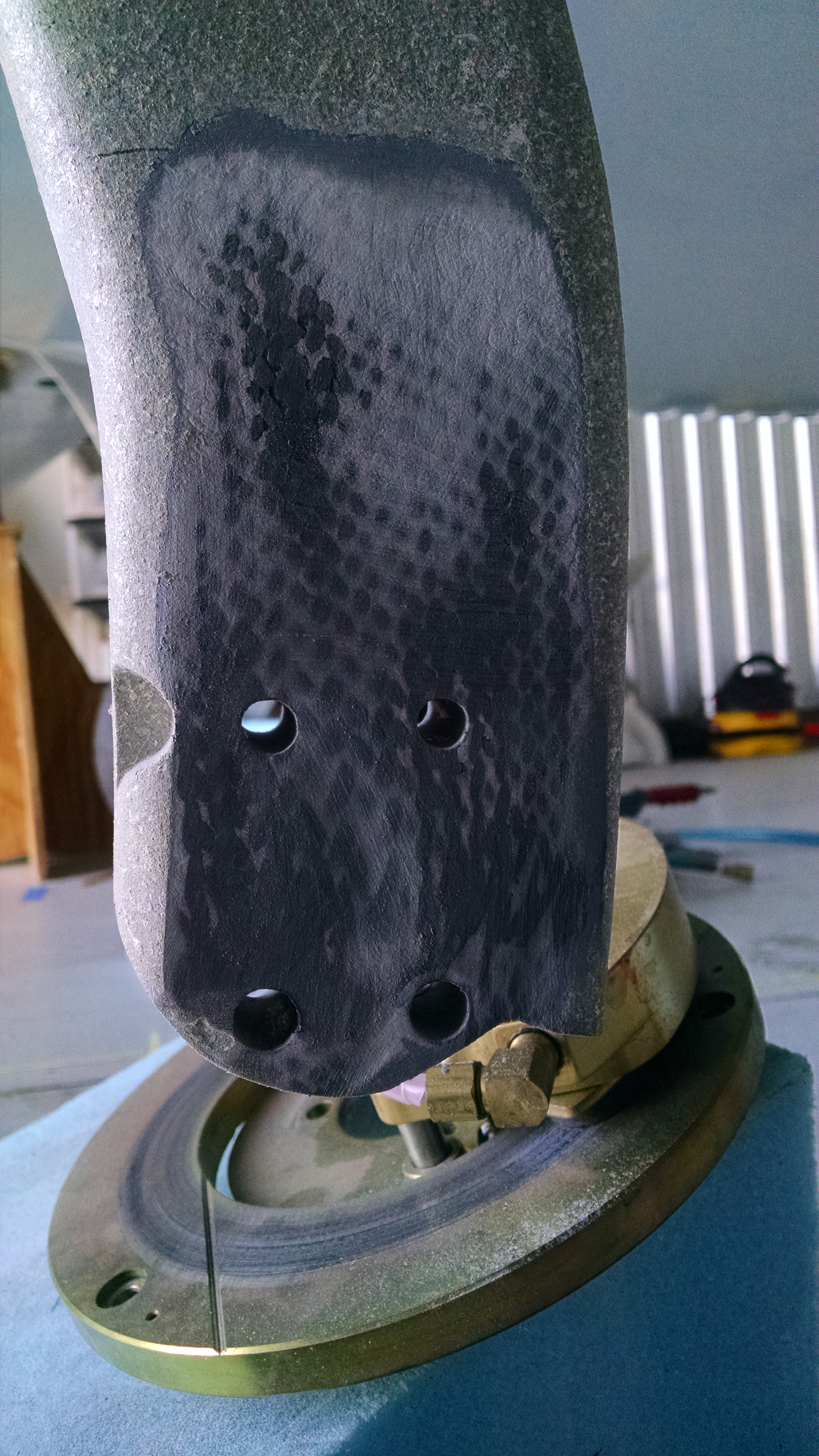
I used my large Permagrit board to remove and flatten the bottom of the gear leg without removing too much of the carbon fiber. While doing that, I discovered some rather concerning cracks from the bottom/front holes to the lower edge of the gear leg.
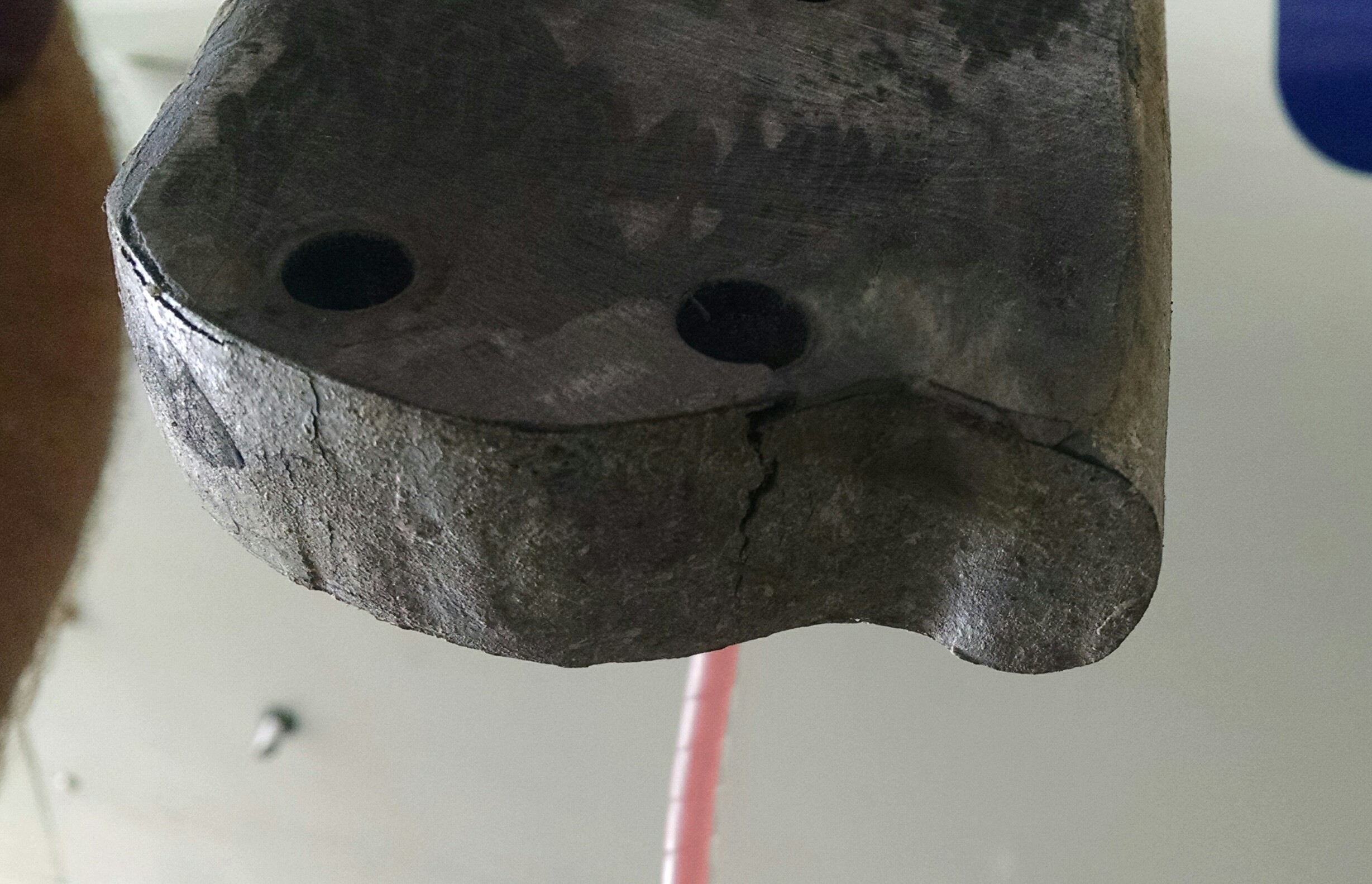
When I was drilling these holes, I thought they were awful close to the edge, but there’s no way to mount the brakes otherwise. I checked with Scott and he confirmed that the cracks are not unusual given the location. Good thing there’s three other bolts!
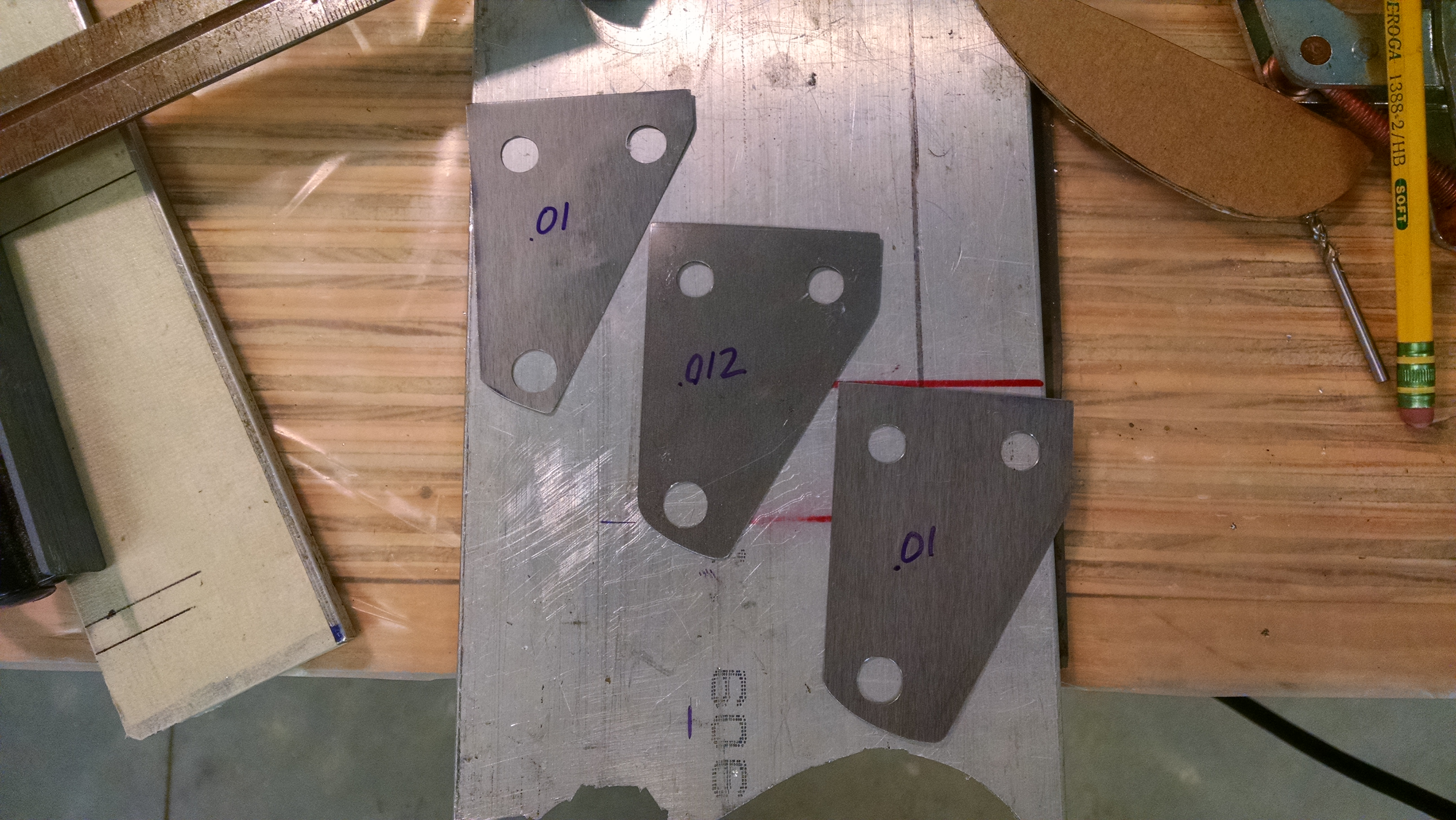
I ordered some steel shim stock from McMaster-Carr for $19. I could have used aluminum that I had laying around but I wanted something that didn’t conduct heat as quickly.
So I put everything back together and checked the toe-in. The general rule is that .010″ of shim will change the toe-in by 1″. But there’s no guidance on adjusting camber.
I started with .032″ of shims on the top (to eliminate the negative camber) and rear (to get some toe-in.
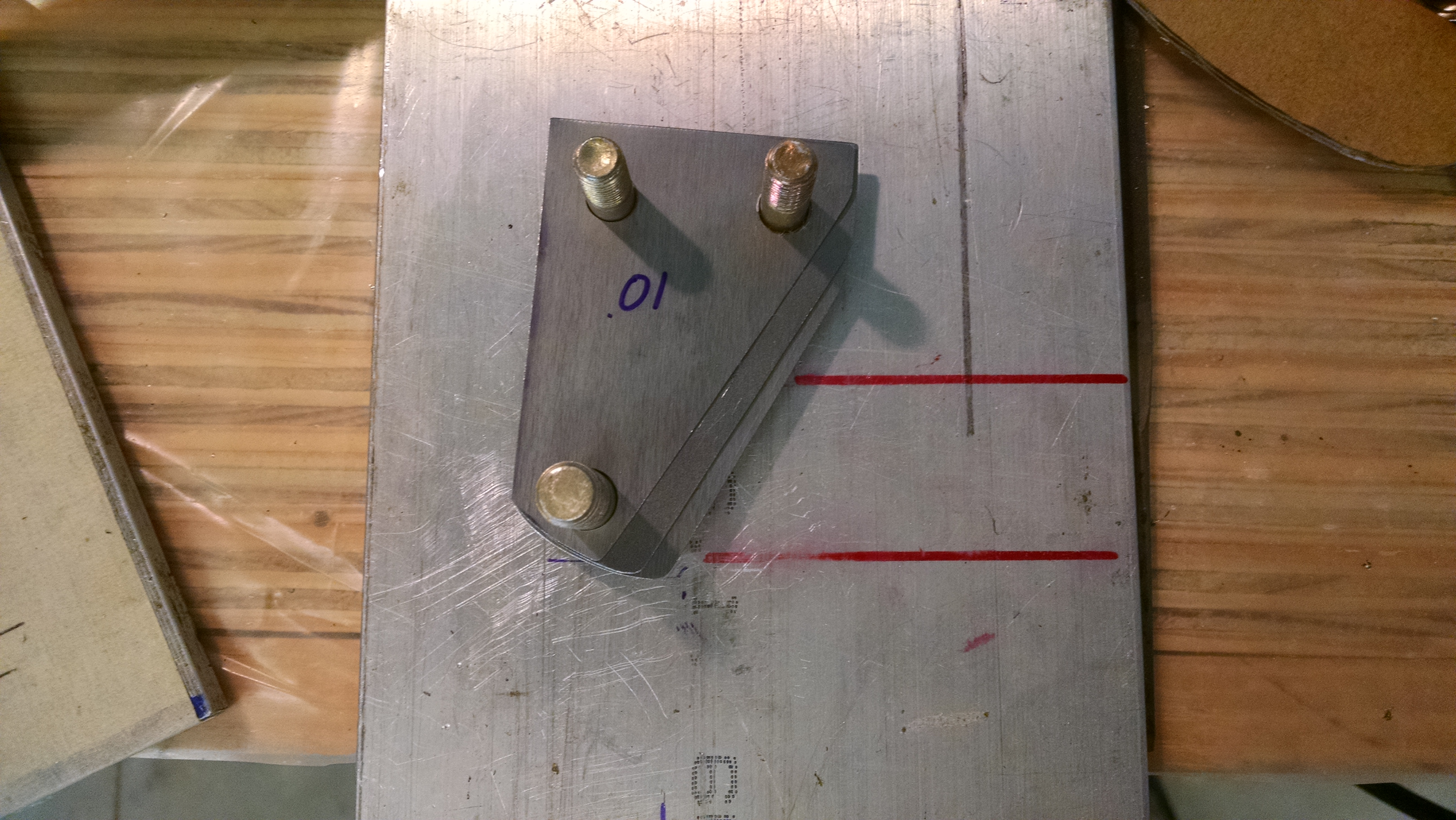
Because of the geometry, I also made some wedge shims for the top/rear.
But when I put everything back together, I getting the same behavior as before where the resulting readings where all over the place. So I decided to eliminate the space in the center.

Once I did that, I was getting consistent results. Then I just kept adding shims to the top and rear until I got neutral camber and 1″ of toe-in. It took a few days because at first I was re-measuring everything after every change. Then I got it figured out so that it only took a few moments of positioning (you have to roll the airplane back 10′ and then forward 5-6′ to get the gear properly loaded and positioned.
Checking the wheel alignment solo.
When Malcolm and I were doing the alignment the first time, it was pretty quick because with two people, it’s easy. Not so much with one person.
Here’s the sequence:
- Get the main gear properly loaded and positioned. This is done by rolling the aircraft forward at least 5′. Because of the toe-in, this will move the wheels towards the centerline.
- Establish the centerline. Take some masking tape a place on the floor directly beneath the nose and the center of the prop (or spinner). Drop a plumb-bob from the nose and prop center and place a mark on the floor.
- Using a string (or laser) connect the mark on the floor at the nose with the mark and the tail. This is your centerline. Now the nose wheel is in the way for this step. There are two workarounds: a) raise the nose and put two small wood blocks on either side of the nose wheel leaving a space for the string. b) make a mark 3″ to the right (or left) of the actual nose and tail marks. When you do this, you will have to adjust the next step 3″ to identify the centerline.
- Place a piece of masking tape about 7″ forward of the main gear axles and mark the centerline.
- Mark the location of the outside of the wheel (not the tire) 7″ forward of the center of the axle. There are a couple different tricks to accomplish this. I used a piece of scrap 1″ square stock with a notch for the tire. Then using a plumb-bob, place a mark the floor (actually, the masking tape on the floor). Do this for both wheels.

- Measure the distance from each wheel to the centerline mark and write this down. Do not be surprised if the two numbers are not identical.

- Measure to the left and right of the nose mark and place marks on the floor that correspond to the distances you recorded in step 6. I placed a strip of tape marking a one inch intervals.
- Now we have to project a line from the wheels to the front. The manual uses long aluminum I or box beams and deflating the tires so the aluminum will contact the wheel and not the tire. What I did was to take a piece of 1″ square aluminum stock to it that was just long enough to span the wheel rim and tape that to my laser level. Now I can shoot the laser up front.

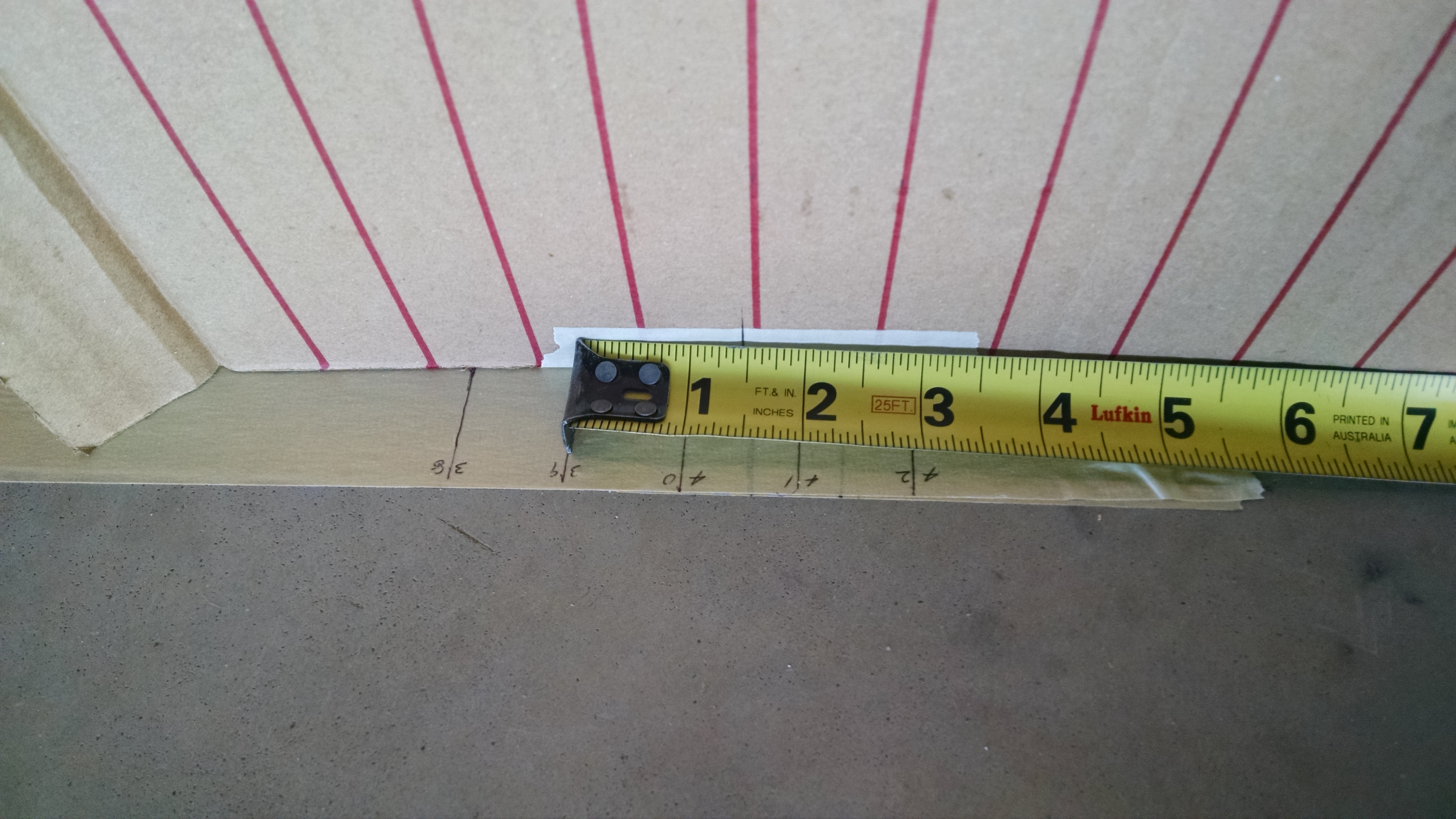
- If there was another person, they could use a tape measure to see if the laser dot was 1″ inside of the mark on the floor. Since I was alone, I made a target out of cardboard. I drew vertical lines that were 1″ apart. Then I placed a mark on the cardboard 1.15″ inside of the zero line (that is the distance from the 1″ bottom of the 1″ square stock to the laser. Place the target on the floor so that the reference mark is on the spot on the floor and now you can shoot the laser at it and see if you have the correct toe-in. My laser also has a flat line option so I can use that to check the camber as well. But that line is rather dim so I have to make the hangar somewhat dark to see it well.


- Final, successful results


8.99 – Cracked wheel
During the annual condition inspection this year, I was tightening the three screws which hold the brake disc onto the wheels. One of them was not tightening. I thought that maybe I had stripped the head.
Turns out the threads in the wheel are what got stripped.
I called Matco to see if a helicoil was an approved fix. While waiting for a callback from an engineer, I pulled the wheel because whether I could use a helicoil or had to replace the wheel, it was going to have to come off anyway.
Once it was off, I looked at the hole and decided that replacement was the only option.
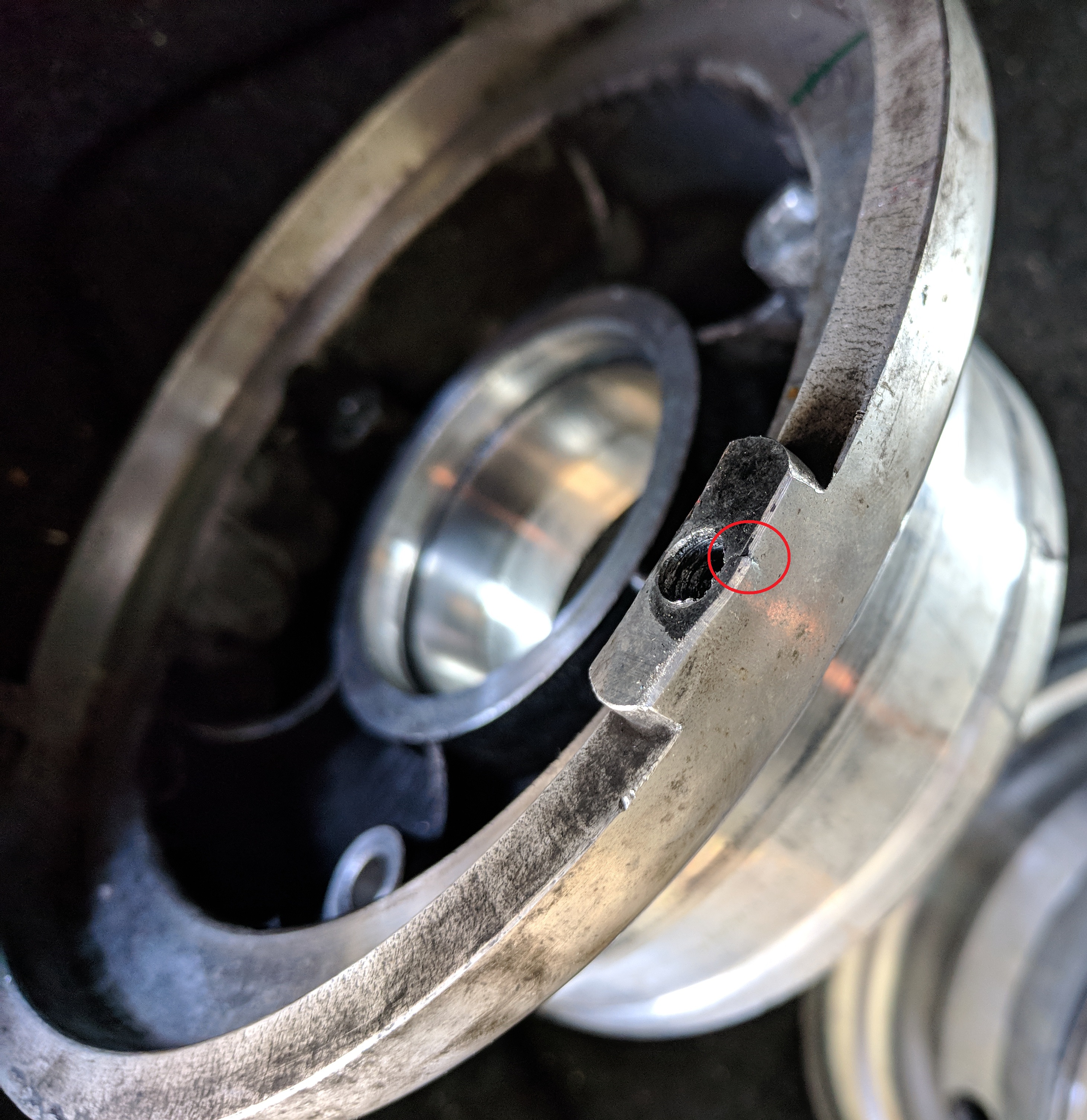
The crack around the hole makes fixing it a non-starter.
When I spoke to Matco, they said that if I sent them the wheel that they would replace the half with the crack for $90.
So off it went.