9.4.1 Fuel Cap Remediation

This entry is part 16 of 18 in the series 09 - Fuel System

I wasn’t present when the fuel cap installation began. When I saw how they were installed, I wasn’t nuts about them but I wasn’t certain that they were not… optimal and didn’t want to make a stink about it. Besides, I figured it would be a real pain to fix anyway. But after looking at planes at Sun-n-Fun and Oshkosh, I knew something had to be done.

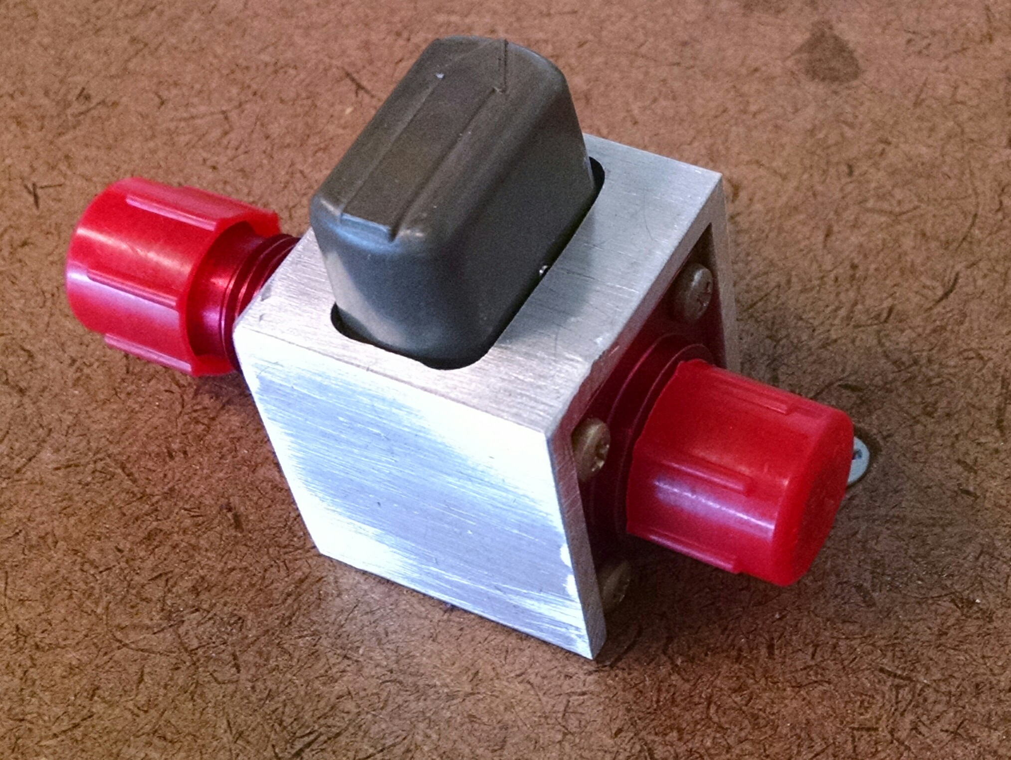
Here’s what the fuel caps look like.

2009-03-29 1748 IMG_8496 2009-03-29 1748 IMG_8495

I wanted a flush installation. I think part of the problem was that these fuel caps aren’t the ones that come from the factory. Those were kind of cheap looking with a fair amount of plastic. So I found a company that makes fuel cell caps for race cars. No plastic, all metal, very high quality.

The first order of business was to cut out the cap. I first cut out just the cap itself. But then I realized that I would need to put a backing plate inside. So I cut the hole into an oval.

2009-08-08 0800 IMG_9129

Here’s the hole with the backing plate.

2009-08-08 0800 IMG_9130

Then I cut a hole into the backing plate and put on a couple coats of Jeffco (fuel resistant epoxy). Once it was dry I mixed up some more Jeffco and added some Cab-o-sil (thickener) and spread it around the edges. Then I put the backing plate inside the fuel tank and pulled it up against the inside of the tank.

Now I had to make a mounting flange. So I clamped the fuel cap collar to a piece of 1/4″ aluminum stock.

   2009-08-08 0802 IMG_9132

Drilled (and tapped) the holes for the collar.

2009-08-08 0810 IMG_9134

Then I marked the center for the BAH (Big Assed Hole).

2009-08-08 0823 IMG_9135

Then I used a hole saw to drill the BAH.

2009-08-08 0903 IMG_9136

Finally I cut out the outside. My 15 year old jig saw really wasn’t up to the task. But the outside cut wasn’t critical.

2009-08-08 0912 IMG_9137

Then using Jeffco with cab-o-sil to thicken it, I secured the flange in place.

The next step was to cover the screw holes with some duct tape. (Here I’ve done all but one) Then fill in any voids with thick Jeffco and cover the whole thing with fiberglass.

 2009-08-08 0800 IMG_9131

Then I cut out the holes, plopped some some thick Jeffco down the screwed down the collar to the mounting flange. Once it cured, I filled and sanded the surrounding area:

2009-08-12 1910 IMG_91392009-08-12 1910 IMG_9140

Much better.

9.7.1 Fuel Line Installation

This entry is part 1 of 18 in the series 09 - Fuel System

Today was a frustrating day. Task # 40 in the flow chart is “construct sump tank”.  Which I did a couple years ago. Then I had to lop off the lower corners because I’m running a Continental engine. There was no specifics on how much to cut off so I looked at what other builders did and duplicated that.

Now that my engine is installed, I discover that the washers for the engine mounts are interfering with the sump.

The sump tank should not be assembled until the engine has been installed. Then the positioning of the sump and the location of the cutouts can be correctly determined. As it is, we had to spend a fair amount of time adjusting the sump to clear the engine mount washers. But once that was done we can start running the fuel lines.

Here the supply lines from the strakes are run to the sump and the vent lines are started.

And a closeup of the copilot side supply line.

9.7.1 Fuel Sump Drain

This entry is part 2 of 18 in the series 09 - Fuel System

The manual calls for the sump drain to be installed in the bottom of the sump. A hole is then cut into the bottom of the fuselage.

Malcolm has a different approach. Install the sump drain remotely. Move it forward and to the pilot side. This approach has two benefits. One; In the event of a gear up or gear collapse, the fuel system will remain intact. Two; It is easier to drain the sump to check for fuel contaminates.

First a pilot hole is drilled through the fuselage close to the whaletail and pilot side wiring duct. Then the hole in enlarged from the outside to accommodate the drain valve.

Then the pilot hole is enlarged to accept the tubing.

Finally, the 1/4″ fuel line is run from the sump, through the gear bulkhead to the drain valve elbow.

9.7.1 Fuel supply line

This entry is part 4 of 18 in the series 09 - Fuel System

The fuel from the sump to the engine will be the next to last of the fuel lines to be run inside the cabin (The vapor return line is the last).  The line runs from the bottom/front of the sump, through a shut-off valve and then to a bulkhead fitting that passes through the firewall.

Here’s the line from the sump to the bulkhead fitting.

and the engine side of the bulkhead fitting.

9.7.1 Fuel vent lines

This entry is part 3 of 18 in the series 09 - Fuel System

The strake fuel tank vent lines that connect to the cross were run a couple days ago. I’m still waiting for one fitting for the fuel return line. But the main vent line can still be run.

This line is a real piece of work. From the cross, up to the roof, then a turn forward to a U-turn. Back to the firewall and down. Then a jog to the co-pilot side and down again. Bump out to clear the spar and back a little to fit in a groove in the sump and out the bottom of the fuselage.

This is the result after a couple hours of bending.

And installed.

9.7 Fuel Shutoff Valves

This entry is part 5 of 18 in the series 09 - Fuel System

The fuel system is rather simple.  There are the two strake tanks (out near the wings) which each feed into a center “sump” tank which in turn has a single line going to the engine.

Unlike most other aircraft which have valves that allow you to select which tank you are supplying the engine with, the Velocity only has a single shutoff valve between the sump tank and the engine. And it’s not controllable from the pilot’s seat.  So basically there is no “fuel management” in a Velocity other than to not run out (of fuel).

To accomplish that, I’ve got fuel gauges that will need to be calibrated. To do that, you add fuel, 5 gallons at a time to one of the fuel tanks while configuring the engine monitor until the tank is full. The problem is that when you add fuel to one tank it goes into the sump and then flows into the other tank. Now there is a method to accomplish this which involves disconnecting the strake-to-sump fuel line and attaching a flexible line to the strake with a shutoff valve.  Then you add the fuel in 5-gallon increments until full and calibrate the fuel gauge.

Then you drain that fuel into 5-gallon jugs and repeat on the other tank.

But I had an idea. Put shutoff valves between the strake and sump tanks. This will allow me you calibrate the fuel gauges and it would also let me isolate the main fuel tanks if I ever need to do maintenance.

Here’s the pilot side strake-to-sump fuel line.

2015-01-20 0948 IMG_20150120_094807767 (Large)

And here’s the valve that I plumbed in.

2015-01-20 1746 IMG_20150120_174622587 (Large)

Still not sure about the whole thing. It adds a bunch of connections (each one being a potential leak) and the only time that I’ll probably ever use it is when I calibrate the fuel gauges.

9.7 Fuel Shutoff Valves

This entry is part 17 of 18 in the series 09 - Fuel System

Back January of 2015 about 6 months before first flight, I picked up some gas valves from Home Depot and installed them between the strake tanks and the sump tank. I was a bit uncertain about the setup because… it just didn’t feel right.

2015-01-20 1746 IMG_20150120_174622587

A couple of days after I put these in, I was talking with Scott at the builders center and he mentioned that someone had put in similar valves and that apparently they didn’t agree with avgas and began leaking.  He suggested checking and making sure the valves were compatible with liquid gas as well as gaseous gas.

I tried but couldn’t verify compatibility so I pulled them out.

Fast forward to Sun-n-Fun 2016.  Walking around the B&B Aircraft Supply tent I ran across these.

2016-04-05 IMG_20160405_1300326712016-04-07 _20160407_093054

They are used in a helicopter, spring loaded in the open position and really small. At $50 each, they aren’t cheap, but they are aviation grade so there’s no question they’ll standup to avgas.

Because the valve is spring loaded, all it takes is the slightest bump and the valve will spring open. So I got some aluminum C channel and make a safety lock to hold them closed.  There’s even a safety wire hole to make sure they stay in place.

2016-05-02 _20160502_1417452016-05-02 _20160502_141729

This week, I borrowed some fuel jugs and defueled enough gas to install the valves. Because the downstream end is a bulkhead fitting, it would have been nice to install them in the gear bulkhead, but it is way too thick for that. So I settled with having the B-nut fitting snugly in the hole in the bulkhead.

Here’s the right side fuel line with shutoff valve installed.

2026-08-25 IMG_20160825_142549213 2026-08-25 IMG_20160825_142625783

9.99 Fuel Imbalance

This entry is part 18 of 18 in the series 09 - Fuel System

One of the things that I’ve noticed on the cross-country flights I’ve made is that the right tank has been running lower than the left tank. Sometimes as much as 10 gallons.

Now in the Cessna, that type of behavior is almost always the result of a misaligned fuel vent for the tank.  But the Velocity doesn’t have fuel vents for each tank.  It has one vent for the entire fuel system.   The other thing that causes it is a bad seal or gasket on the fuel cap.  Since the top of the wing is in a low pressure area, any leaks at the fuel cap will cause the tank to depressurize slightly and draw fuel from the other tank.  The final possible cause of fuel imbalance is if the airplane flies with one wing low.

So I checked the level of the plane in flight.  Perfectly level.

Next, I taped over the fuel cap on the left tank. No change.

Then I started looking more closely at the symptom.  On the ground, the tanks are pretty equal. During the initial climb, they’re equal.  It’s not until I get to level cruise that they start to diverge.  So I graphed out the fuel tank levels with the airspeed. Sure enough, the faster I go, the greater the imbalance.  This is a huge finger pointing at a bad seal around the fuel cap. But I checked that by taping over the cap!

At this point I’m questioning my sanity.

So I started looking at the data again (this is where full flight and engine data monitoring comes in real handy).

Here’s the graph of a flight down to Sebastian and back.

fuel-graph

Notice the fuel levels are within a couple gallons of each other on the ground but as the airspeed increases, the levels diverge (the spikes where they level out is where I was slipping the plane to see if I could balance them out).

But then I noticed something. The left tank level is a relatively smooth line while the right tank level varies about 2 gallons (the sample rate is one second). So now I’m wondering why the left tank varies .1-.2 gallons per second while the right tank is changing 10 times as much.

I called the owner of the company that makes the fuel probes and controller module (who is also one of the owners of Grand Rapids). He said that the controller module averages the readings over about 5 seconds and transmits them engine monitor.  So there’s really no way that the readings should be changing that quickly. He sent me a replacement controller… Which meant that I had to calibrate it. 🙁

After installing and calibrating, I made a test flight.  Fuel levels were never more than 2 gallons apart.  And the graph line looks just like the left tank.

fuel-graph-11-02

So I never had a fuel imbalance problem.  I had an instrumentation problem.

Oh well.