I don’t mean to go off on a rant here…
One of my jobs when I’m not training (the thing that pays for the airplane) is writing training manuals. So I’m a bit more critical of instructional material than your average person and I’m constantly finding areas of this manual that need improvement.
After talking with other builders, this seems to apply to a lot of homebuilt aircraft, not just Velocity’s.
On to the task at hand… From the sequenced flow chart, I need to install the “Pitch Trim Actuator”. Up and down movement of the airplane in flight is done with the elevators. Pull the stick back and the nose goes up. Push the stick forward and the nose goes down. In cruise flight, you don’t want to have to be pushing forward or pulling back just to stay level. So a small electric motor moves a spring to a position that will apply the necessary force so that you don’t have to push or pull the stick to maintain a particular attitude.
This task has to do with mounting this electric motor.
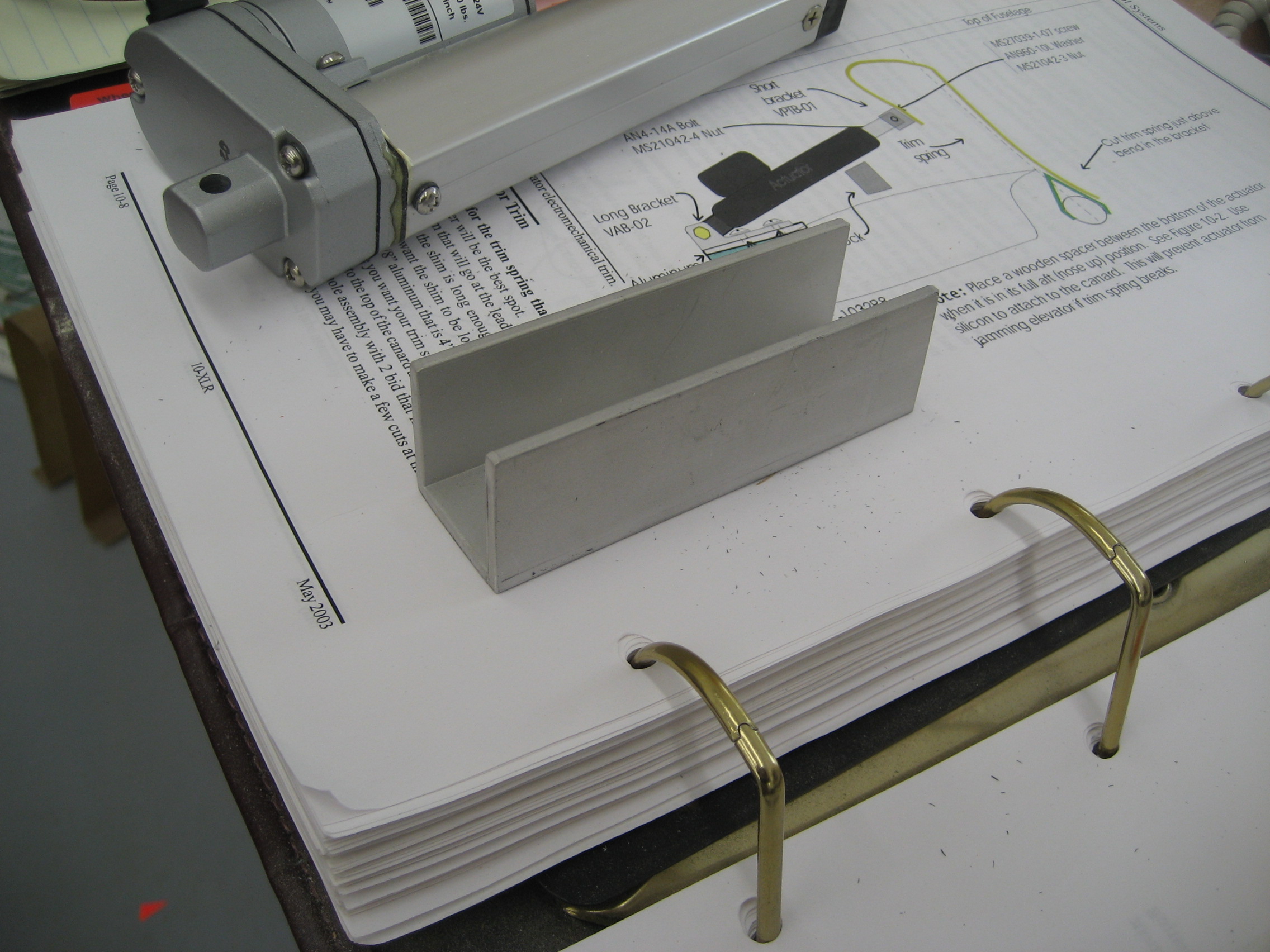
Here’s a page from the manual:

This is looking from the left side. The canard is on the bottom. The large black object is the actuator. On the left is where it mounts to the canard by means of the “Long Bracket” (Part Number VAB-02). The bracket will be connected to the “Aluminum Hardpoint” which will sit on the “Shim”. Seems pretty straightforward.
Here’s the text:
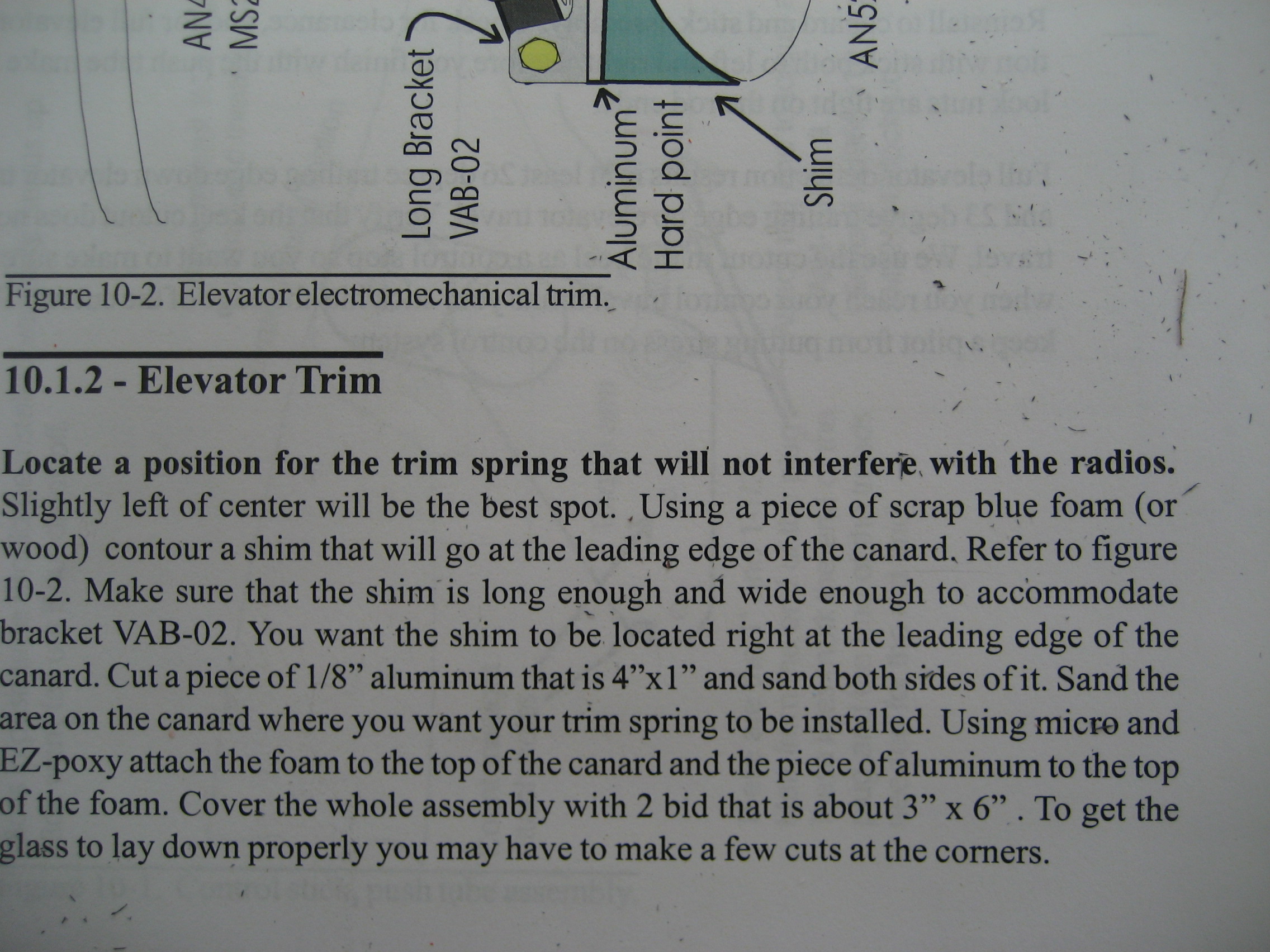
Hmmm. The first sentence is in bold. Must be important, huh? “Located a position for the trim spring that will not interfere with the radios.”?!?!?!
What radios? Installation of the radios is a LONG way away. Heck, I don’t even HAVE the radios. Nor have I even decided what radios or where they’ll be installed. So how do I figure out where to put this thing? I looked at the websites from other builders and looked at their pictures. Hopefully, my location will be fine.
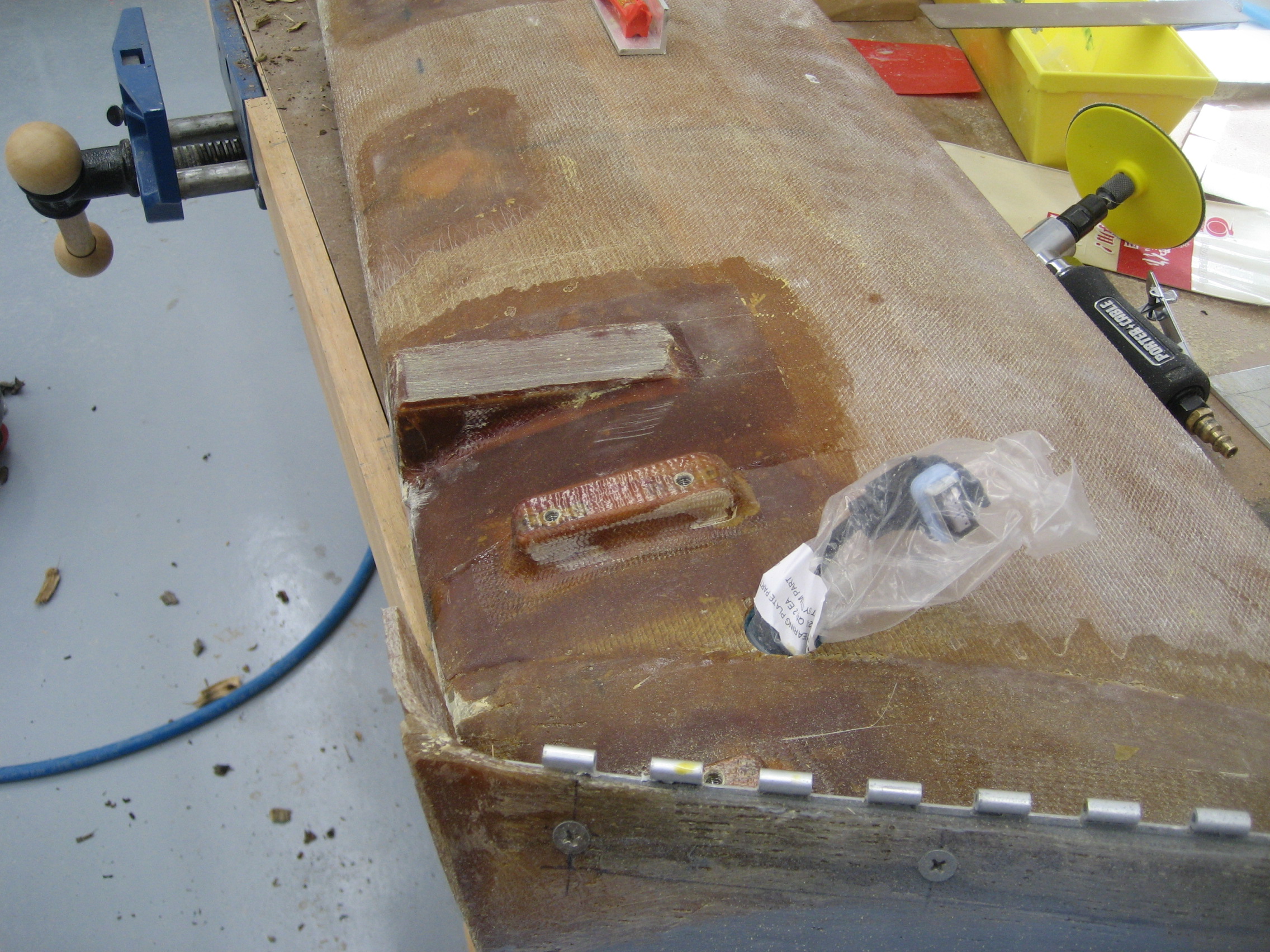
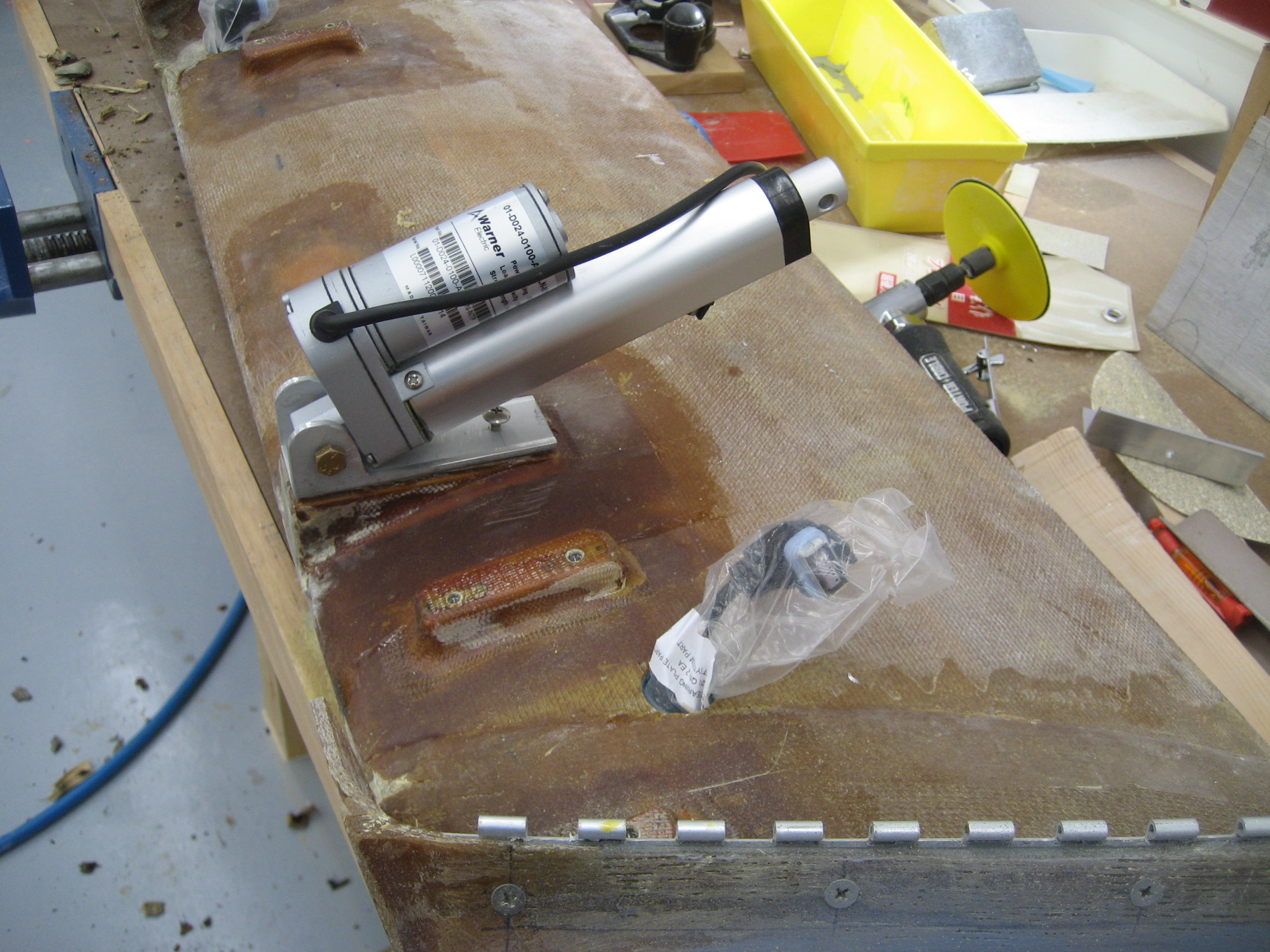
This is the area of the canard where I’ll mount the actuator.
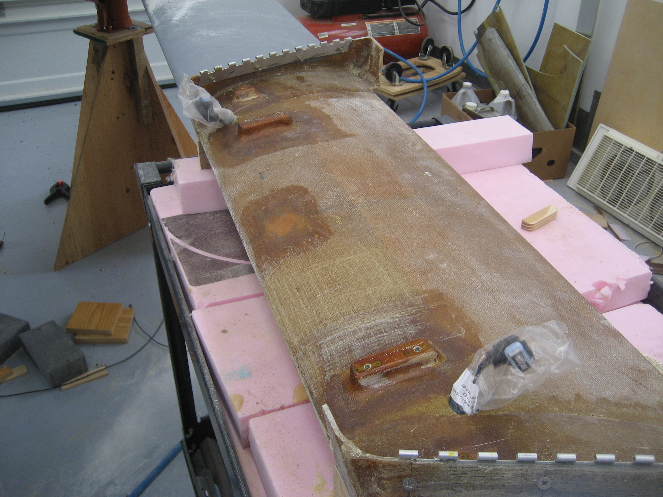
The piece of blue foam cut and formed to the correct shape is the “shim”.

A piece of aluminum cut to size on top.

Everything covered with two layers of BID.
The actuator.

The “Long Bracket”.
Wait a minute… The actuator looks like the picture of the actuator, but the bracket doesn’t look like the bracket. Back to the manual where we see the text “Modify the long bracket (VAB-01) as shown in Figure 10-2 to allow the actuator to move up and down.”
Well this is getting interesting. I’ve got to cut this piece “as shown” in the picture. No dimensions, no template, just make it look like a picture in a Hanna/Barbera cartoon. Okay, that shouldn’t be too difficult, just cut it so the end of the motor will fit.
But wait a minute… In figure 10-2 the “Long Bracket” is part number “VAB-02” but in the text they say “Modify the long bracket (VAB-01)”!
Now what?
So I reread the entire section repeatedly trying to determine exactly what I’m supposed to be cutting. In the end, I come to the conclusion that the text is wrong and the figure is right.
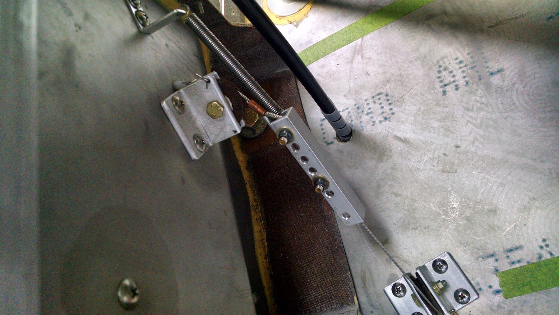
Long Bracket (VAB-02) after modification.

Hardpoint drilled, tapped with Long Bracket (VAB-02) and trim actuator mounted.
If I had to do this task again, I could probably do it in an hour. But with the research on the location, the part number discrepancy and trial and fit for the modification of the bracket, I probably spent the better part of 6 hours on this.
At this rate, I’ll be done in ten years. 🙁