13.5.2 Cabin Lighting

This entry is part 53 of 67 in the series 13 - Electrical / Instruments

First I built my overhead courtesy lights. Click here for a refresher.  I even etched my own circuit boards.

Then I decided to add an “all on” feature which required a circuit board redesign. For version 2, I had the circuit boards etched by a company that specializes in that work.

Then I decided that I wasn’t happy with my dimming choice.  There’s a good chance that I’ll want to dim these lights. My plan was to connect a potentiometer (variable resistor) to the supply side. But LED’s are weird little ducks. With incandescent lights (24 volt, for example), they begin to glow with about 1 volt and get brighter with increasing voltage up to 24 volts. So to dim incandescent lights, you connect a pot (short for potentiometer) that allows you to adjust the voltage going to the lights.  This works just like the dimmer in your house.

But like I said, LED’s are different. First, they’re current driven instead of voltage driven. But to keep things simple, we’ll approach this from the voltage side. The second (and this is what caused my current problem) is there operating range. The LED’s I chose were 3 volt LEDs (I reduced the voltage to the LED’s using a fixed resistor). But here’s where the dimming problem came in. These LED’s don’t start to light until about 2.4 volts. So with the pot installed, you turn it and nothing happens for the first 3/4 of a turn and then the slightest movement of the knob causes a huge difference in brightness for the remaining 1/4 turn.

So I had to educate myself with how to power and dim LED’s. So I started looking for dimmers. I found a guy that makes a bunch of stuff for the experimental aircraft market. He makes a dimmer called EGPAVR (Extraordinarily General Purpose Adjustable Voltage Regulator). With it, you can define the lower and upper voltage levels for your lights. So I picked up a couple and started testing my new design. One other modification I made was to increase the number of LED’s in each fixture. You can always dim or turn them off, but you can’t make them brighter than max brightness.

Here’s my test setup. The LED’s are on the breadboard. The EGPAVR is to the right. A variable resistor used to determine the fixed resistor values is to the right of the EGPAVR and I have two meters to monitor the voltage and current levels.

2010-04-10 1540 IMG_03982010-04-11 1526 IMG_0412

Once I had the values for the fixed resistors determined, I designed my new circuit boards and sent them to be etched. When they came in, I disassembled the old lights and got to work.
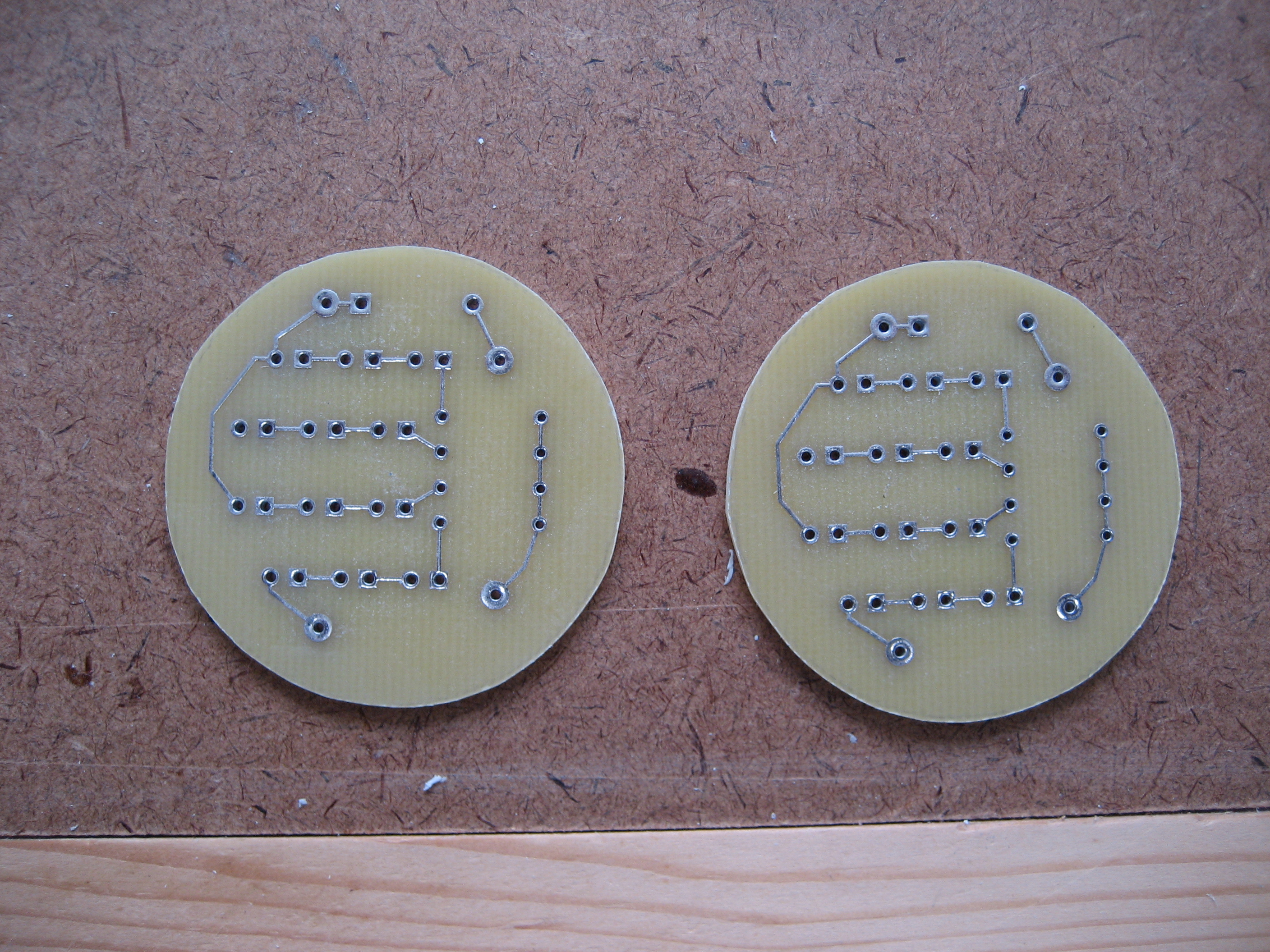
The new PCBs

2010-04-10 1539 IMG_0397              

Each card and circuit boards for two light fixtures.

Marked for cutting.

2010-04-10 1547 IMG_0401

And after cutting.

2010-04-10 1556 IMG_0402

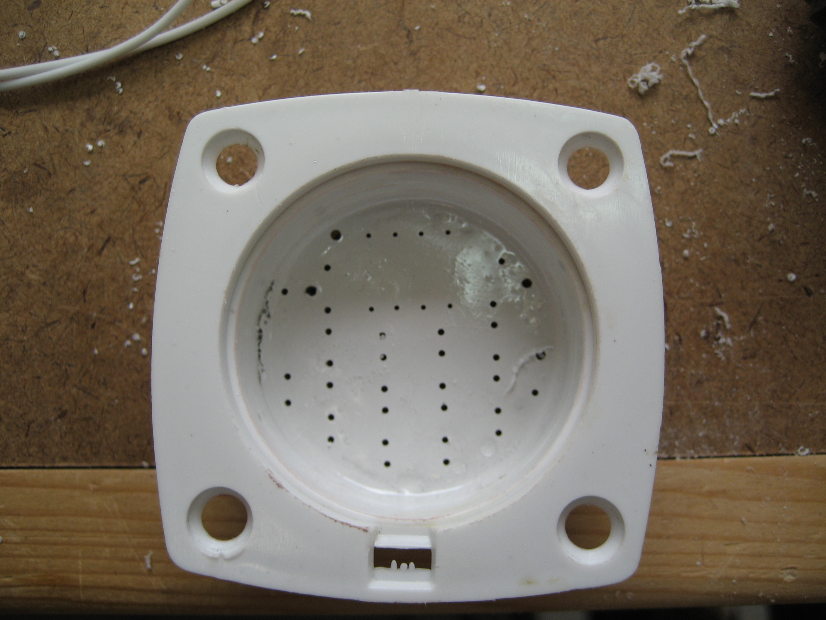
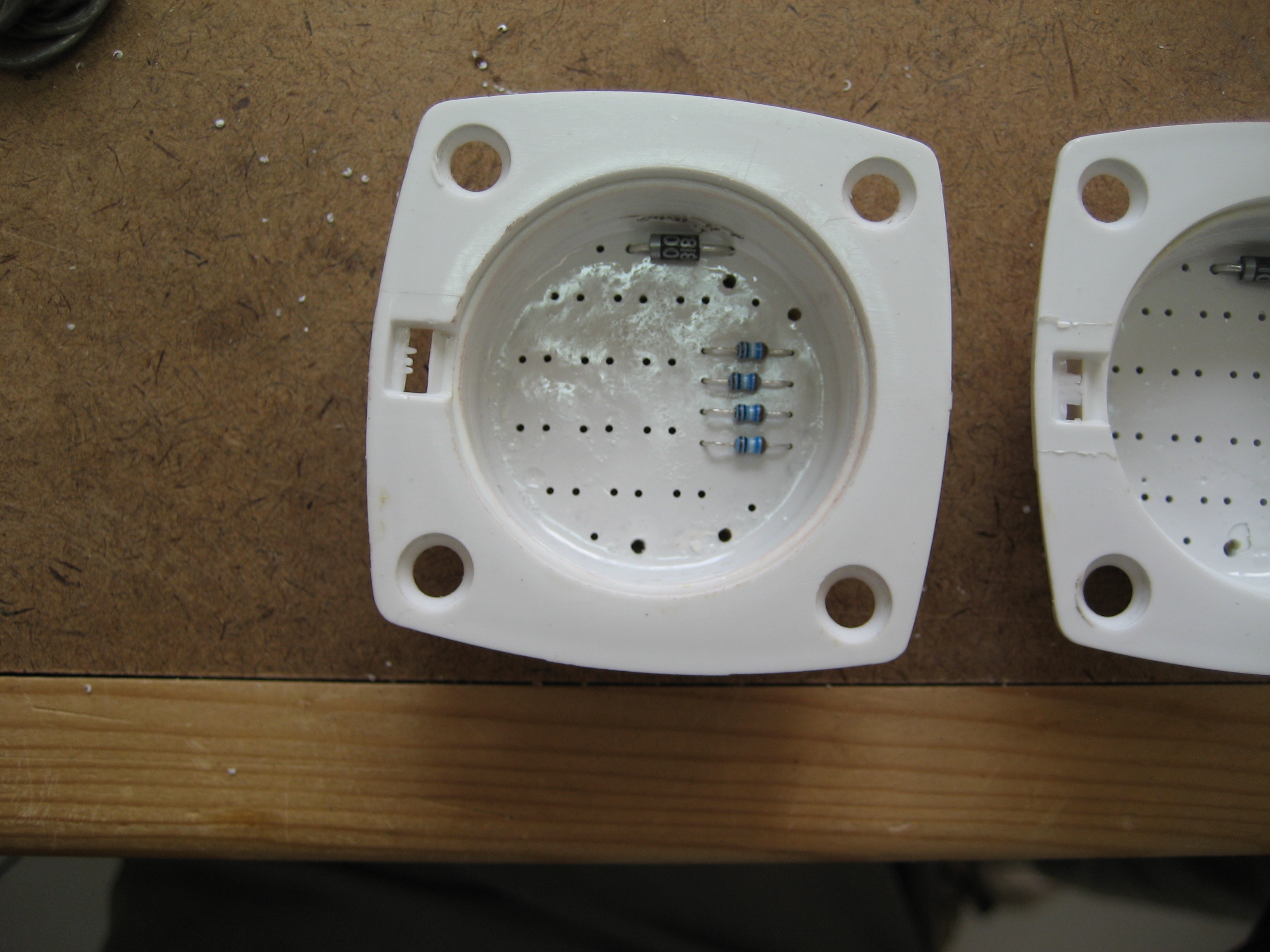
Here the light fixtures ready for assembly.

2010-04-10 1543 IMG_0399

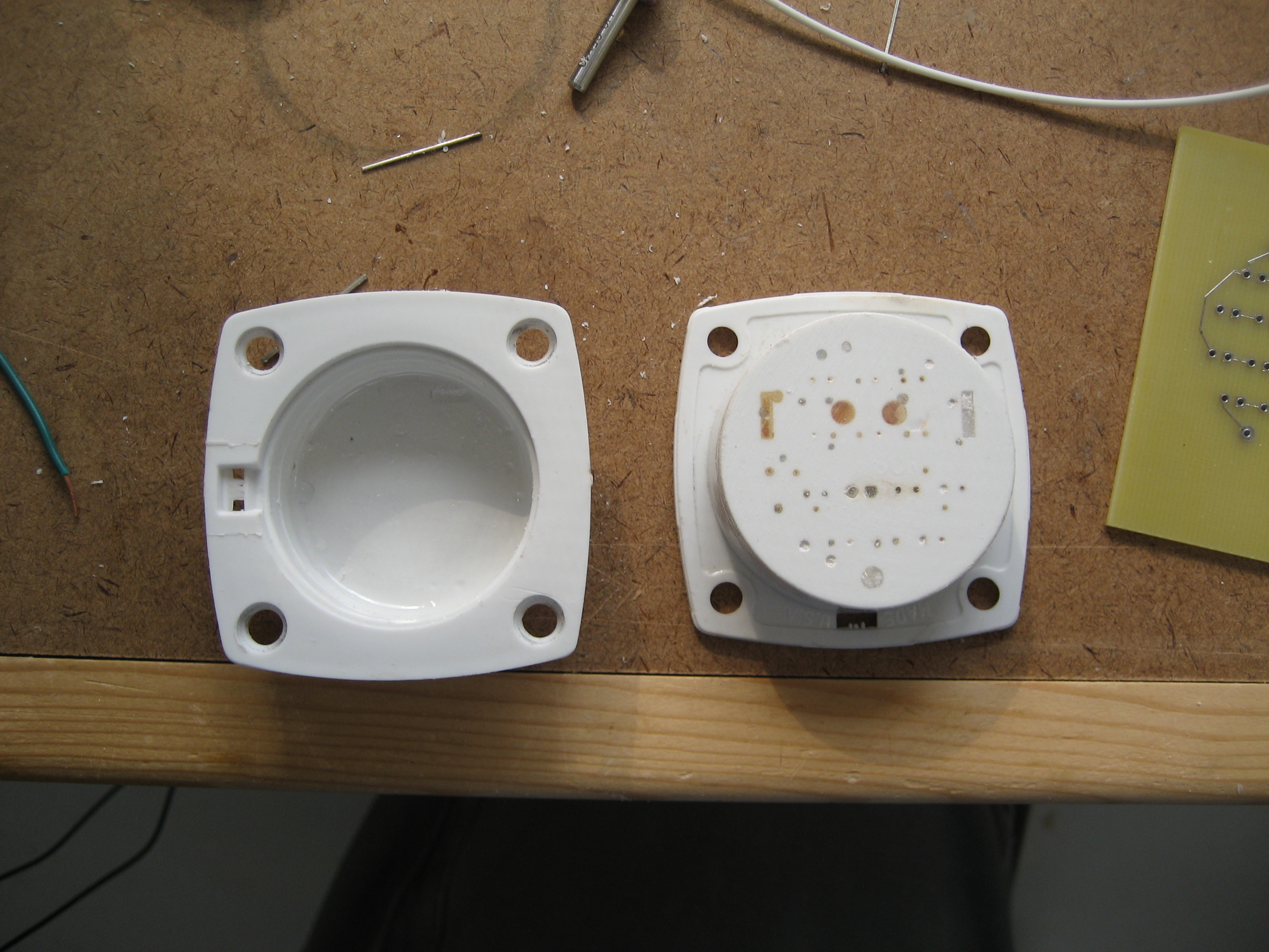
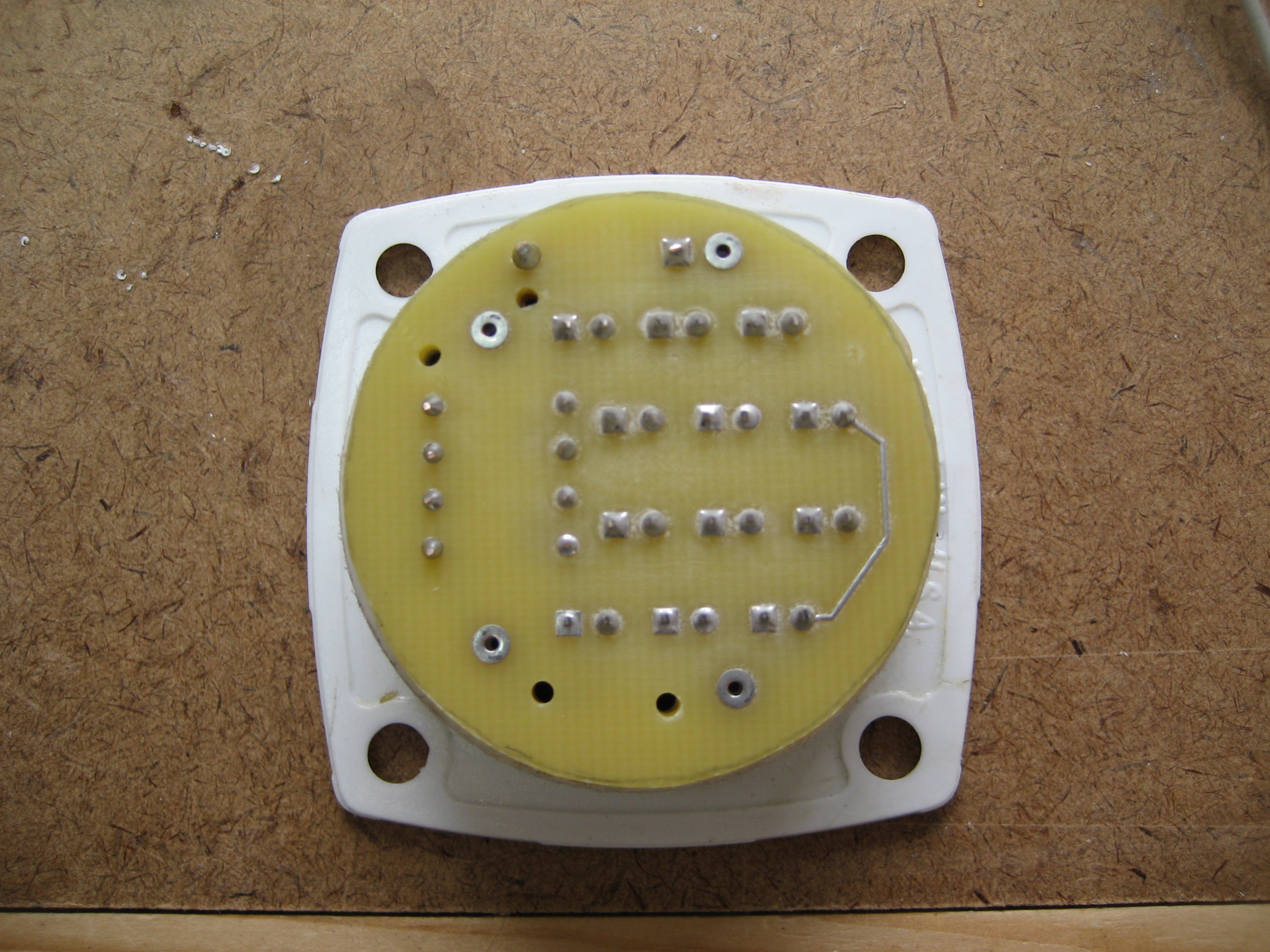
Circuit boards have been mounted to the back and holes drilled.

2010-04-11 1347 IMG_0404

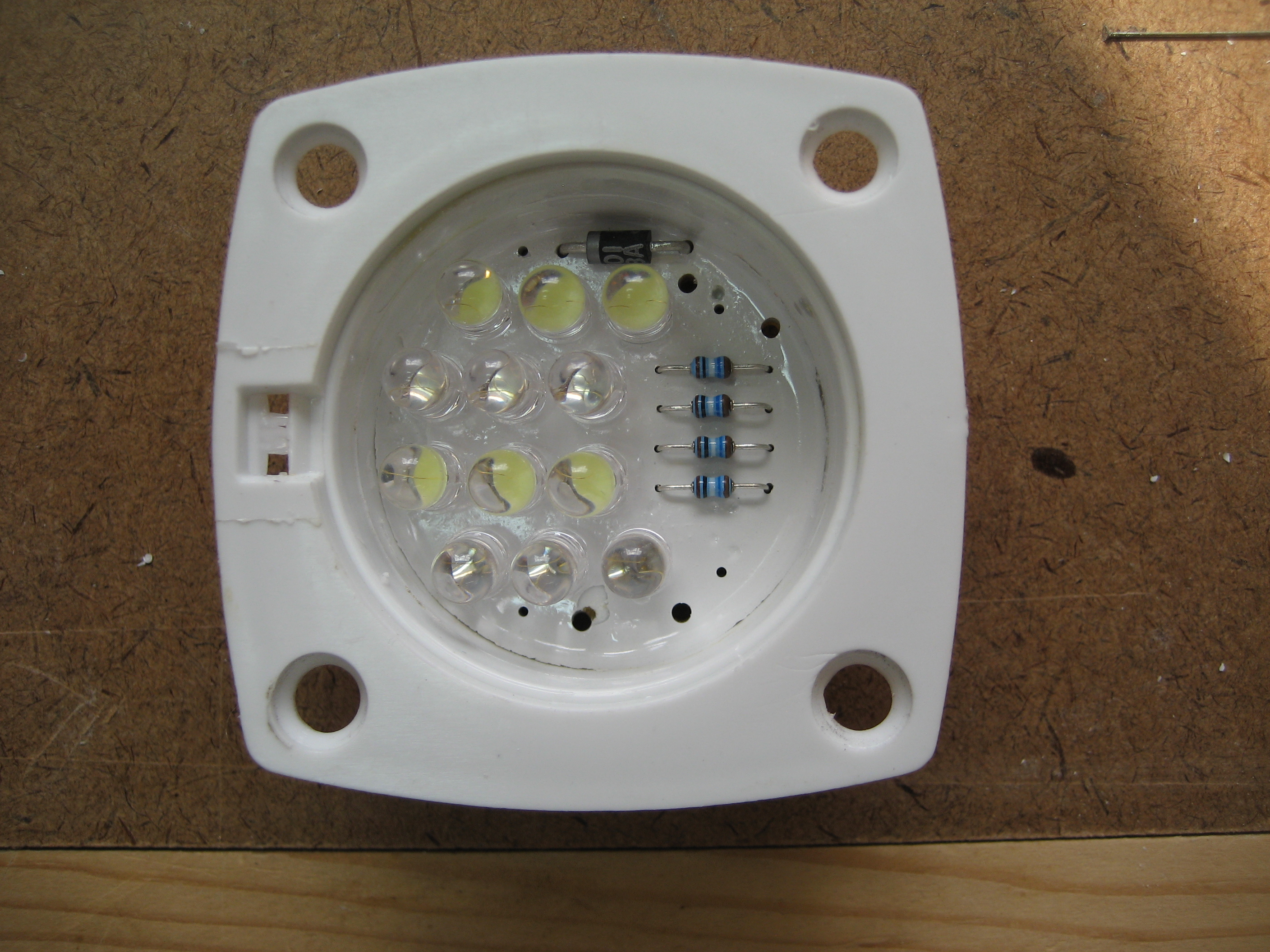
Resistors and diode inserted.
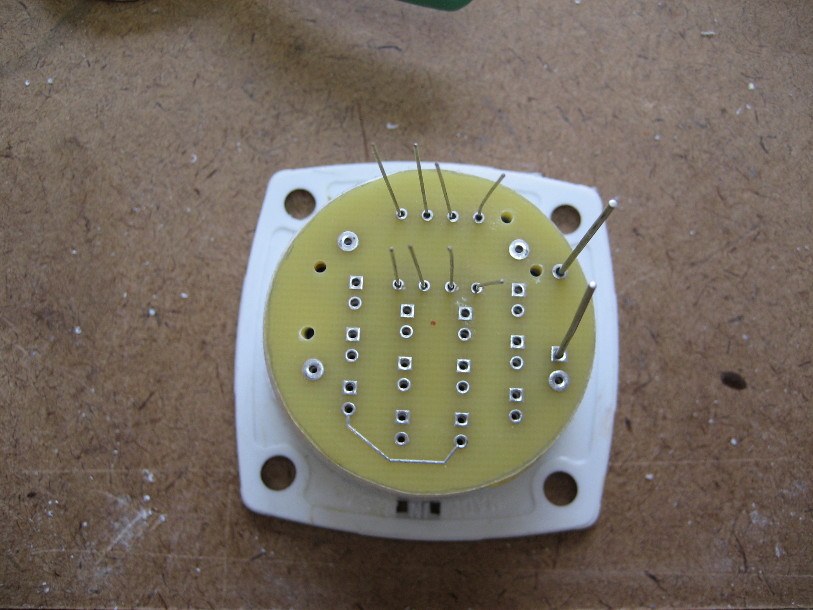
2010-04-11 1406 IMG_04052010-04-11 1415 IMG_0406

LEDs mounted.

2010-04-11 1448 IMG_04082010-04-11 1454 IMG_04092010-04-11 1526 IMG_0411

And finally the wiring harness and connector installed

2010-04-11 1721 IMG_0413


13.1.4 Glideslope Antenna

This entry is part 54 of 67 in the series 13 - Electrical / Instruments

While waiting for the paint (yeah, yeah, yeah. Primer) to fully cure, I build the glideslope antenna. I used the RST Engineering foil and placed it between the bottom of the windshield and the doghouse opening.

Here’s the two pieces of foil that will be the two legs of the antenna.2010-10-16 0755 IMG_0734

And after the coaxial leads are attached and then covered with thickened epoxy and then a layer of BID.
2010-10-16 0848 IMG_0735

Sadly, I would later learn this was a TOTAL waste of time. The Nav radio that I purchased didn’t have an input for the glideslope antenna.  When I asked the manufacture, they told me that they get the signal from the VOR antenna and that almost nobody uses separate glideslope antennas anymore.

13.3.4 Overhead Switch Panel

This entry is part 55 of 67 in the series 13 - Electrical / Instruments

When I’m not in SC, there are still things that I can do at home. Electrical system planning is one. I’ve already designed the courtesy lights. Now I’m working on the Overhead Switch Panel (OSP). The OSP is part of the A-Beam (it goes across the inside of the roof between the A-Pillars) and can have switches or indicator lights. There are many approaches to this. For example:

Andy Millin’s OSP
amillinOSP
Terry Miles’ OSP
2009-12-18 1319 IMG_9598
 I don’t remember who’s this one is
OH1

 Rich Guerra’s OSP
rguerraOSP
 Fred’s OSP
2008-01-18 1225 IMG_5774
 The Factory Demo Plane
IMG_9104

Now Andy has some really sweet lighted and engraved rocker switches! But because My A-Beam has a very low profile, I don’t have enough room for the rocker switches that Andy is using. So I decided to go with traditional toggle switches.

There are a couple issues to be dealt with on this panel.

  1. It’s real easy to reach for one switch and hit some turbulence and end up turning something on or off that you didn’t mean to.
  2. Most of the time when you’re flying, you are either looking outside or at your main instrument panel. If you’re flying IFR (Instrument Flight Rules) then you’re looking only at your instrument panel.

Switching your view from outside (straight ahead) to the main panel isn’t that difficult. You move your eyes a little and refocus. We do that every day when we drive. But looking at the OSP will possibily require moving your head and refocusing your eyes to something less than 12 inches away. This can be very distracting. So it would be nice to not have to ever look at the OSP when flying.

Here’s how I’m going to deal with these.

  1. I’m going to install switch guards on all the switches. That way, it will be almost impossible to “bump” into an adjacent switch. They also give your hand something to rest on when you’re activating a switch.
  2. I will also only use the switches for functions needed during engine start and engine shutdown. This way, I’ll never have to even think about these switches during flight.
  3. The sequence on activating the switches will be left-to-right for engine start and right-to-left for engine shutdown.

I took my aluminum OSP plate and drilled the holes for the switches and switch guards. At this point I’m not 100% certain of the sequence so this is just a temporary switch panel until I can determine which switch goes where.

Here’s the temporary OSP.
2010-11-20 1221 IMG_0805

Once I’ve got the sequence determined, I’ll use a service like Frontpanelexpress to cut, drill and engrave the finished panel. Here’s what I think it will be.
OHP

13.4.3 Pitot Tube Installation

This entry is part 1 of 67 in the series 13 - Electrical / Instruments

The pitot tube is what measures the airflow so that we know how fast the airplane is moving through the air. This sucker was pricey too. Malcolm had some steel stock with the same cross-section as the pitot tube. So I cut a length of it and drilled four mounting holes in it.

The manual calls out the location of the pitot tube as 6.75 inches below the canard and 18 inches forward of the door.

+ marks the spot.

Closer

And the hole is cut out.

The sleeve and pitot tube dry fitted.

Then the structural adhesive is mixed and the sleeve is permanently installed. The alignment is important to insure a correct airspeed indication.

Forward alignment is accomplished using a framing square clamped to the canard bulkhead and visually referencing the pitot tube to the framing square.

And we used a digital level to verify that it’s… level. The tripod is used to hold the position while the epoxy sets.

13.4.2 Static Port

This entry is part 2 of 67 in the series 13 - Electrical / Instruments

While I was waiting for the bolts to arrive, I installed the static ports. The manual calls out 9″ below the canard and 9″ aft of the canard bulkhead. They used to be mounted lower and farther aft but I like the higher/forward position.

Once the location is identified, a .5″ hole is drilled.

The foam is opened up, masking tape is used to cover the static ports, structural adhesive is applied and it’s installed.

13.2.1 Instrument Panel Mounting

This entry is part 3 of 67 in the series 13 - Electrical / Instruments

I mounted the instrument panel a while back. That task involved creating mounting tabs on each side of the fuselage and a mounting tab on the center keel. Then nutplates were riveted to the tabs. It worked fine but the problem is that it will be almost impossible to remove the panel once the engine controls (Throttle, prop and mixture) are installed. There are a couple of approaches to work around this issue. Malcolm’s is to create a sub panel that the engine controls are mounted to and that sub-panel is permanently attached to the fuselage.

First, the location of the engine controls is determined. There’s a bit of guesswork involved since I don’t know what the correct spacing between the controls should be until they’re drilled. So I checked with a couple other builders and came up with 2 – 2.25″ between each control. I went with 2.25″.

This picture shows the left side of the instrument panel with the location of the Throttle, Prop and Mixture controls. I’ve also created the line where EC (Engine Control) sub-panel will be cut away from the main panel.

Partial cuts are made in two places along the two lines. Then structural adhesive is applied to the back of the sub-panel and the whole panel is screwed and clamped into position.

Once the adhesive has cured, the cuts are completed and the main panel is removed leaving the sub panel attached to the inner skin of the fuselage.

Then tape is applied to the front and back of the main panel and a release agent is applied.

The main panel is reinstalled and reinforcing layups are applied to the back of the sub-panel and extended over the back of the main panel. This will create a flange that will be used to connect the main panel and the sub-panel.

View from the back of the panel.

Then holes are drilled through the main panel and flange on the sub-panel and nutplates are installed. After that, the holes for the engine controls are drilled into the EC sub-panel.

Next the EC sub-panel will be painted and the engine controls will be mounted.


13.3.2 Ground Power Plug

This entry is part 4 of 67 in the series 13 - Electrical / Instruments

My good friend Albert, gave me a ground power plug. These are helpful if you ever have a dead battery and need a jump or you want to run the avionics on the ground for testing.

But where to put it? After trying a couple locations, under the battery shelf looks like the best location. So a mounting bracket is needed. I brought the plug home with me after the last trip down so I would have something to do.

I got a foot of 2″x1/8″ aluminum angle and cut it in half. Then I clamped the two pieces together and cut an opening for the plug. Then I drilled the four holes for the mounting  bolts.

Next I pulled the two pieces apart and mixed up some Resin Research epoxy and bonded the two pieces back together.

Finally, I drilled six holes along the top and tapped them. This is how the bracket will be mounted to the underside of the battery tray.

13.6.3 Ground Power Receptacle

This entry is part 32 of 67 in the series 13 - Electrical / Instruments

When the battery in a car is unable to start the engine, you can connect a set of jumper cables to get the engine started.  Many FBO’s aren’t real keen on “jumper cables”. Too much potential for connecting them wrong and doing major damage to the aircraft electrical system. Most 28 volt aircraft have ground power connectors. It allows you to connect the single cable to the aircraft with no chance of connecting things wrong.

Albert gave me a Ground Power Receptacle a while back so now all I have to do is figure out where to put it. I was going to put it under the battery tray but once I looked at the size of the plug I realized that wasn’t going to work.

So I put it in the nose. This way, it’s easy to get to on the ground when the nose gear doors are open. People that use the factory nose landing light can’t do this because the landing light is in the way. Yet another advantage of landing lights in the canard.

13.99 Instrument Panel Lighting

This entry is part 58 of 67 in the series 13 - Electrical / Instruments

I’ve got the glareshield trimmed and fitted. This was a major PITA. Lots of putting it in, figuring out where it was hitting, remove it, trim it, put it back in, mark it, remove it, trim it, put it back in…  I must have installed that glareshied 30 times. Then I made some tabs that will be used to attach the glareshield to the top of the instrument panel.

Now it’s time for the lights. I’m using a strip of blue LEDs. The LEDs are about .5″ apart so they will provide about the same type of light as the electro-luminescent lights.

The strip is about .2″ high and to keep the light out of the line of site, I could either create a raised area behind the strip or simply recess it. I chose to recess the strip of LEDs.

First I marked where the LED strip will be then I made the first cut through the bottom layer of glass.

Then I made the second cut. I made this cut farther forward than necessary so I could slope the the opening.  After the cut was made, I removed the lower layer of fiberglass and cut out the foam. The result is a slot with the rear straight up and down but the front has a gradual slope towards the panel.

To accommodate the wires, I drilled a hole between the top and bottom layers of fiberglass that would be the wiring conduit. I used a long drill bit and started from the front edge and drilled back to the end of the slot on the pilots side. Then I drilled a hole from the bottom into the conduit.

The slot is then covered with a layer of BID. Because of the small area, I used a fiberglass veil (very fine fibers).

Once that cured, I trimmed off the excess and painted on a coat of resin to make a smooth surface. The LEDs have a self-adhesive backing and I wanted a smooth surface for that to stick to. I’m not sure what I’m going to do as far as covering on the glareshield, but for now, I painted the underside flat black.

The LED strip is designed for a 12v system. Since I’m running a 24v electrical system, I had to modify the strip and turn it into a 24v strip. Once that was done, I installed the LEDs (little out of focus).

Then I connected the power.

I wanted to see how it would look installed, so once again, I put the glareshield back in.

I’m not nuts about the unlighted portion of the instrument panel at the very top. Mounting the LED strip on the bottom of the glareshield or increasing the slope would have prevented that. But I think I’ll let it go since there’s nothing in that area that needs to be illuminated anyway.

13.6 Electrical supply lines

This entry is part 31 of 67 in the series 13 - Electrical / Instruments

The way most Velocities are setup is with the master contactor (solenoid) and stater contactor located up front next to the battery. With the starter in the back, this means a fairly large gauge wire running back to the starter. It also means two slightly smaller gauge wires running from the alternators to the front.

Now because I’m running a 24v electrical system, I get to run smaller gauge wires than the 12v guys. So my starter wires will only be 4 AWG instead of 2 or 0 AWG.  This is nice because smaller is lighter, takes up less space and is easier to bend.

Copper wire is used throughout the aircraft. Aluminum is lighter, but there have been numerous documented problems with aluminum wire. One to my “go to” guys for supplies is Eric Jones at Perihelion Design. He’s supplied me with servo controllers, LED dimmers and switch guards. He also has this very interesting cable called CCA (Copper Clad Aluminum). It’s an aluminum cable that is covered in copper. So this wire is light weight (aluminum) and doesn’t have the problem associated with aluminum because it is covered in copper. It’s the best of both worlds. 🙂

Since I’m still in recovery mode, I decided to install one of the terminals on the cable just to see how it went. Normally, wire terminals are crimped on, but a good pair of crimpers for wire this big costs a lot of money and I only have about 6 to install. So it’s done in a McGyver fashion.

First I made a tool to hold the terminal and cable with a hole for a punch. Next I had to make a 5/16″ punch (an old screwdriver fit the bill nicely) Then with the cable and terminal held in position, I used the punch to “dimple” the terminal to “crimp” the cable. Then using a propane torch, I soldered the cable to the terminal. This will create a strong, permanent connection between the cable and the terminal.

Here you can see the dimple and how the solder has completely filled the end of the cable.

Finally, shrink tubing is used to cover the work.

I was able to find some yellow shrink tubing instead of the standard black.