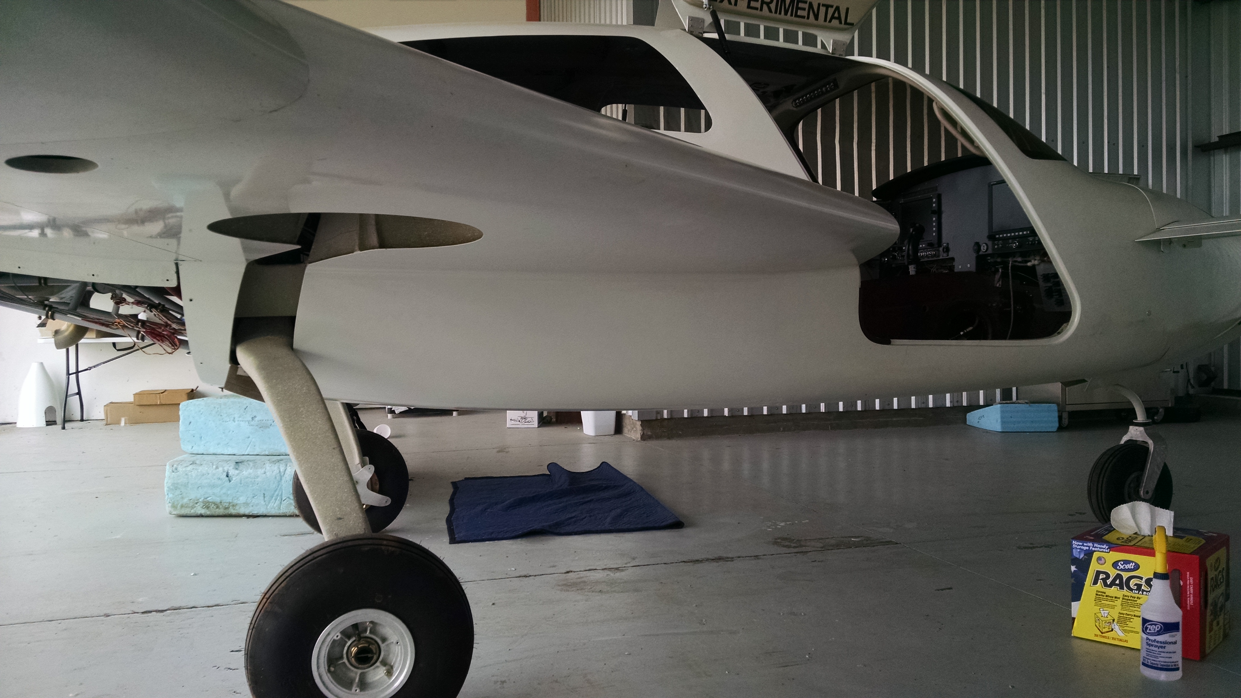
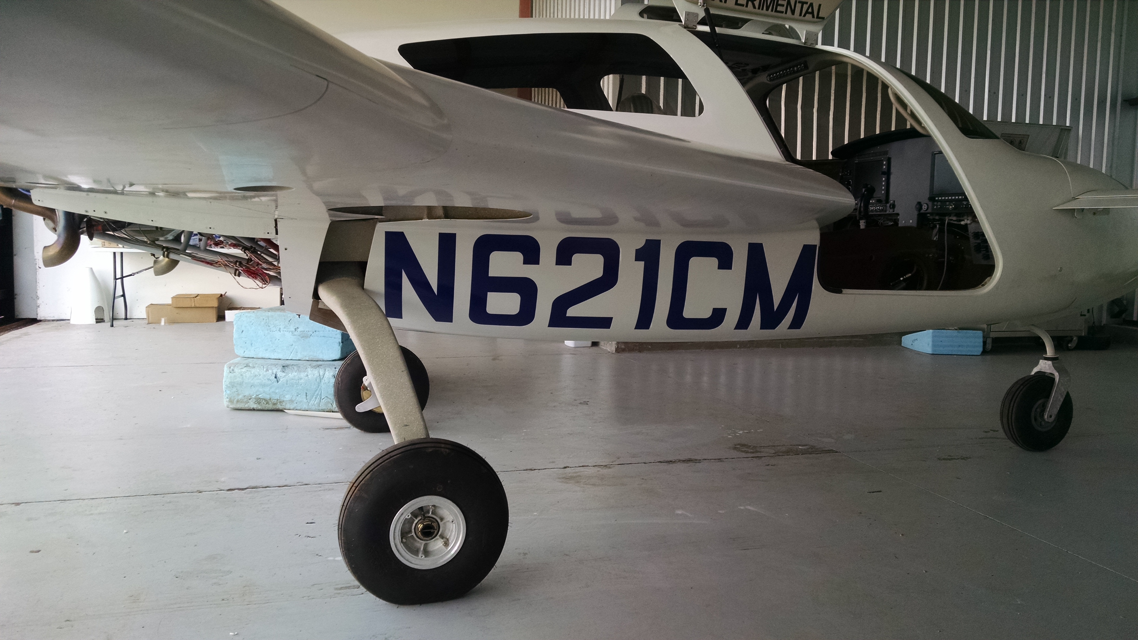
Since I will initially being flying in primer and not paint, there is no reason to go to the trouble of painting on the registration numbers. So I looked for temporary N-numbers. I looked at a couple of suppliers and found Ace Graphics. After exchanging a couple emails with Bruce I placed the order for Royal Blue, Semi Rounded numbers. I chose royal blue because the propeller already has trim paint that looked like royal blue. The N-Numbers arrived while I was down working on the plane.
Before starting to apply them, I hit the area under the strake with some 1500 grit sandpaper to remove any overspray from when we painted the top half.
Once I had a nice smooth surface, I taped the N-numbers to the top of the area under the strake and then cut between each letter/number. Then it was just a matter of peeling the backing paper away and using a spreader to apply the numbers.
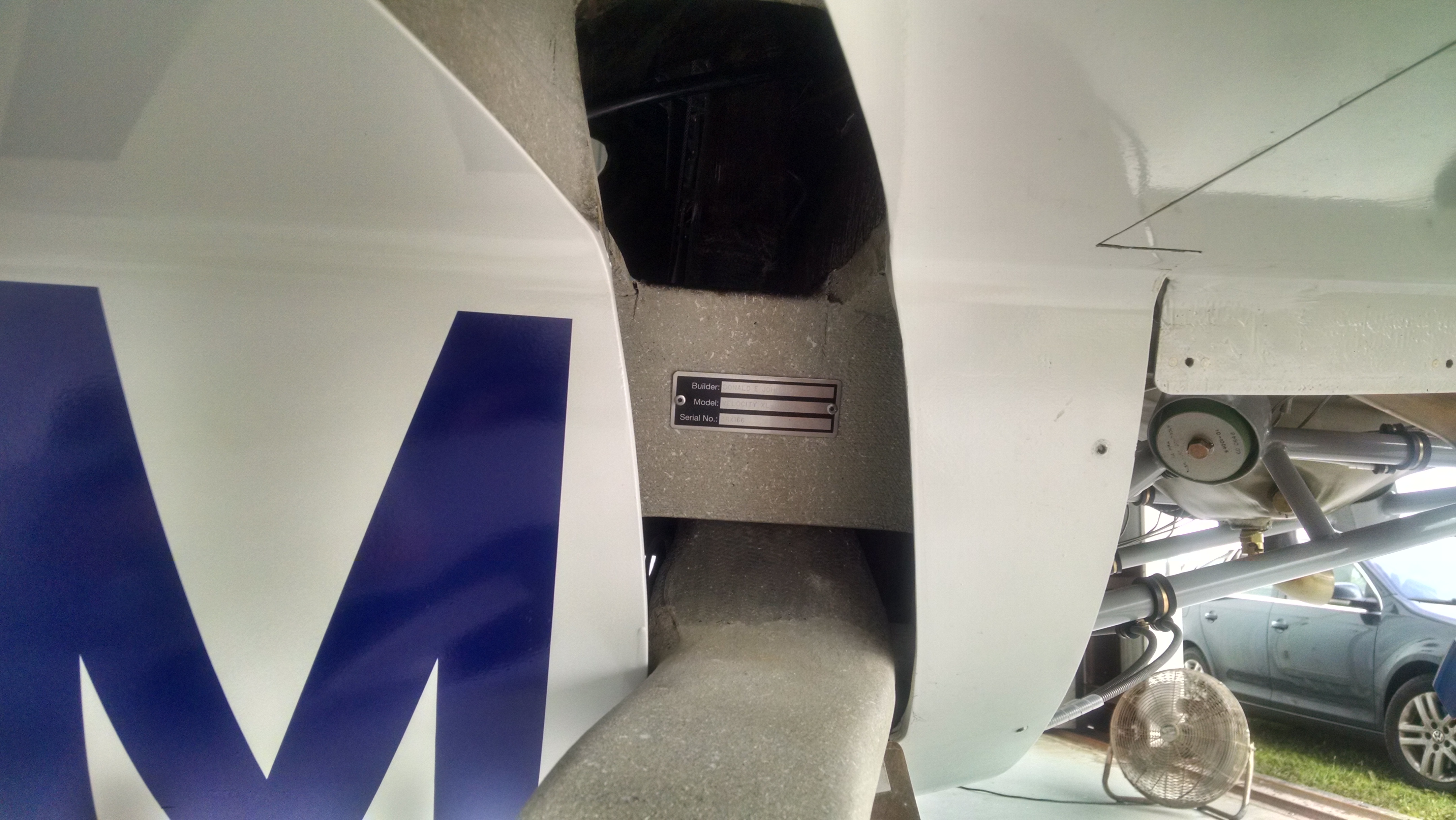
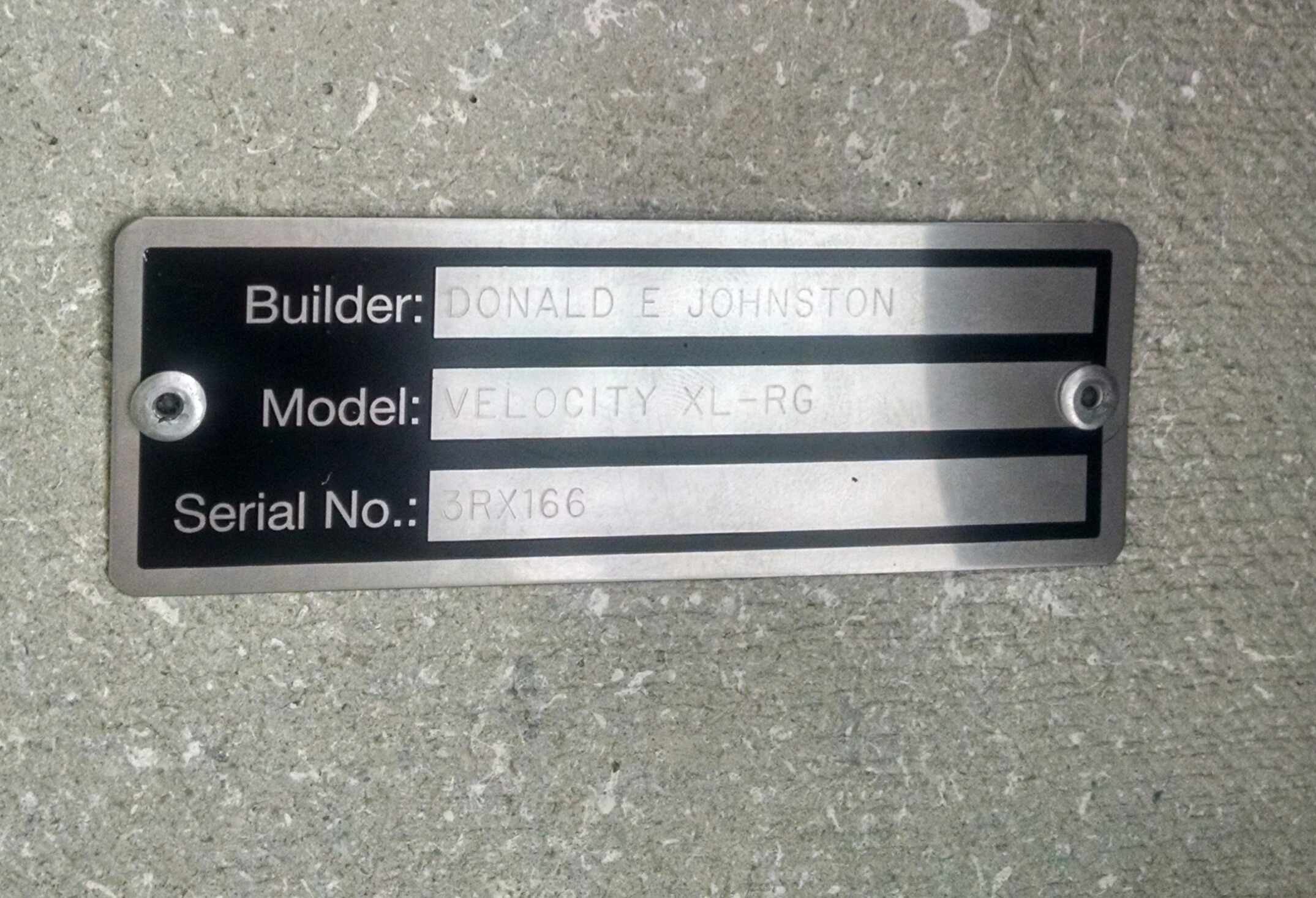
While I was having all the switch panel overlays engraved by Aircraft Engravers, I also had them make my data plate.
Some builders put it on the outside of the fuselage but I put it on the transverse bulkhead. It will be visible on the ground but not be on the fuselage skin.
First flight was scheduled for July 7th. We drove down on the July 4th. Ann came down on this trip (for some reason) :-). The last time she was in Sebastian was when we came down to talk to Velocity and take the demo flight in June of 2007.
I spent the 5th and 6th preparing for the flight by finishing up the various odds and ends that needed to be done. On the 6th, the plane moved for the first time under it’s own power.
I was very pleased with the handling compared to the trainer that I flew a couple weeks earlier. After taxiing around for a while, I picked up Ann and we did a relatively high-speed taxi (~ 50kts). Once again, the airplane tracked very nicely. Then we went over to the compass rose to align the AHRS and magnetometers. Then we put it away for the night.
John Abraham came over around 11am on the 7th and began his preflight. While he was doing that I explained the systems that I thought were unique to my plane. The only thing he found was the main gear cables were a little tight. He wanted a bit more slack in them. So we loosened them. He checked a couple other things and then said “Looks like it should fly… Let’s go see.” 🙂
So we pushed it outside.
John started the engine and we talked for a minute while the engine warmed up. Then he taxied off to runway 06.
Ann had a GoPro running and her iPhone at the same time (not sure how she did that). The GoPro video is going to require some post-production work as the plane is so small that you can even see it. But until then, here’s the iPhone video.
John was up about 20 minutes. During that time he check the control response, slow speed handling, monitored the engine and attempted to check the high-speed handling.
After landing, returning to the hanger and shutting down he explained that a flutter developed at about 160kts which limited the speed on this flight. He said that it seemed to be coming from one of the landing gear doors. The only other issue was a slight left roll tendency.
And with that, the first flight was over.
Now, in addition to being an “airplane” on FAA paper, it is also one in reality.
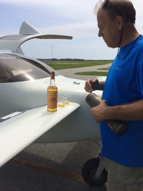
This calls for a celebration!
I’ve been holding my last bottle of Glenmorangie in reserve. I had to do this because the sixteen men of Tain decided to sell their distillery to the French (YGBSM!) a few years ago. The current product, by the way, is barely acceptable for cleaning toilets. But we’ll leave that discussion for another time.
So I brought along my last bottle on this trip. I pulled out a couple of mixing cups because it seems appropriate that the cups which were used to mix the epoxy for this airplane be the preferred container for the celebratory drink.
After the first flight, the first order of business was to get the flutter which was suspected of coming from the gear doors. Since I was having to head up to Illinois and pack up the remaining furniture, I had Malcolm handle those tasks.
When the plane was jacked up and the gear retracted, the nose gear doors weren’t fully closed so Malcolm adjusted those. The left main gear door was hanging down about a 1/4″ so that was adjusted as well. He checked the incidence of the wings to try and determine if that was the cause of the left roll tendency. Both wings were perfectly set. Although the right wing did have some wash-out. But if that was a factor, it would have had the opposite effect. So the roll issue was deferred (for now).
John went up for the second flight on 7/14. The flutter from the gear doors was gone. But now there’s a flutter from the right rudder. The plan was to shim out the rudders and see what that did. The roll tendency toward the left is still there. John and Scott Swing both feel that shimming a wing was overkill and that if I had roll trim it could easily be dialed out.
So before going any further, let’s discuss my decision to skip the roll trim mechanism. First, I wasn’t keen on the factory supplied mechanism. Basically, it was a DC motor with a string wrapped around it a few times. One end of the string attached to a spring and then to the aileron bellcrank while the other end went around an idler pulley and attached to a spring and then to the other side of the aileron bellcrank. Here’s a picture where the string/spring attaches to the bellcrank. Since the motor has continuous rotation, if it turns too far, the string will begin to slip. That slippage also allows the pilot to overcome the position should the motor or motor control fail.
Click here for a picture of a dash-5 roll trim on Jorge A. Bujanda’s build site.
Well this string idea didn’t sit well for me. Geoff Gerhardt came up with a great idea of using a cog belt. So I ordered a drive pulley for the existing motor, an idler pulley and a length of cog belt. Started making the parts and pretty soon I had a good working roll trim mechanism. As I was about to get everything wired up, I started thinking…
I’ve never flown (nor heard of) a single engine piston airplane that had roll trim. I asked around and every A&P and IA that I spoke with said the same thing. Which was, if you’re using roll trim in a light single, you’re fixing a symptom while you should be fixing the problem of why it’s not flying straight. This is what’s known as “rigging” an airplane. I had this done on the Cessna years ago. It involves adjusting the control linkages, setting the incidence of the wings and then flying it. If it doesn’t fly straight, you adjust linkages and wing incidence to get it flying straight. So I decided that this roll trim thing is just a shortcut to properly rigging the plane in the first place.
And with that, I took all the roll trim parts off and put them in a box. No plane that I built was going to have roll trim so that I don’t have to get it properly rigged!
Then I got taken to school by Ken Baker. I hadn’t considered dihedral. All those other single engine airplanes have dihedral built into the wings. Dihedral is where the wings are angled up when looking at the plane from the front (or back). With dihedral, when the plane is level, both wings a producing the same amount of lift. But if the plane rolls to one side, then the lower wing generates more lift and the higher wing generates less which causes the plane to level out… all by itself. So if one side of the plane is just a little heavier (maybe because there’s more weight on side), this dihedral will help the plane fly level.
Guess what Velocity aircraft don’t have?
That’s right, dihedral.
Which means that when they roll just a little, instead to dihedral basically self-correcting the unwanted roll, they actually roll even more. Which is why even minute weigh imbalance or a small difference in the wing shape can create a roll to the left or right.
So the roll trim box is going to have to get opened back up. But that will have to wait until I get back down to Sebastian.
Scott did the third flight. Malcolm shimmed both rudders. At around 165, the flutter developed in the right rudder and caused the entire winglet to begin oscillating. Very disturbing. When they looked at the rudders, instead of the outside surface being slightly concave (or scalloped) or even flat, they were convex (rounded out). This was causing the rudders to “hunt” for a neutral. Which means flutter. That movement transmits to the winglet causing it to start moving as well. If left unchecked it could cause the winglet to depart.
Here’s a main wing oscillation on a Hawker. (Warning: NSFW for language)
So it looks like my rudders were not properly constructed.
Malcolm removed them and began making them right.
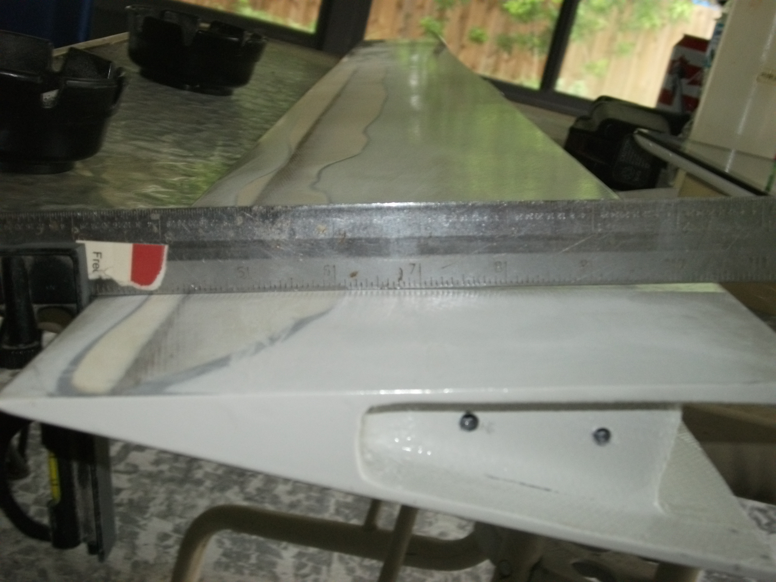
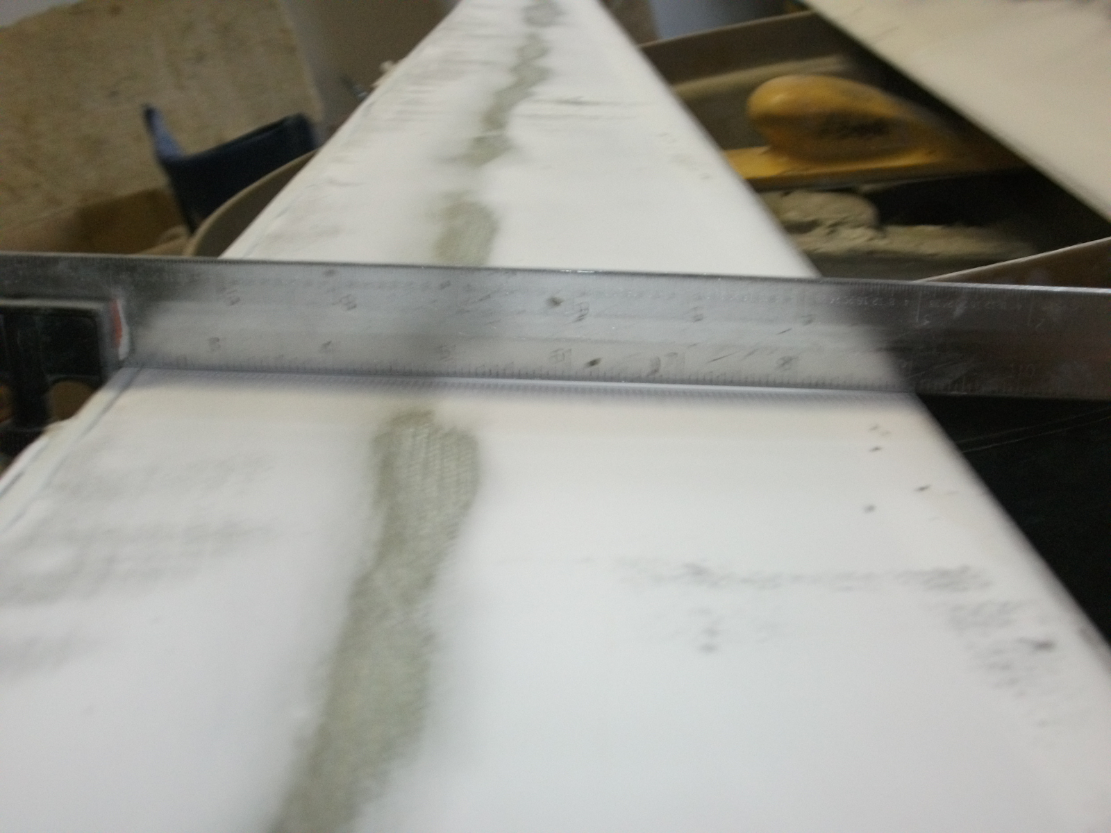
Here’s the outside surface of the right rudder. You’ll notice that it’s not concave or even flat. In fact, there’s a pretty good outward curve on that surface.
After removing all the filler, it’s still not right.
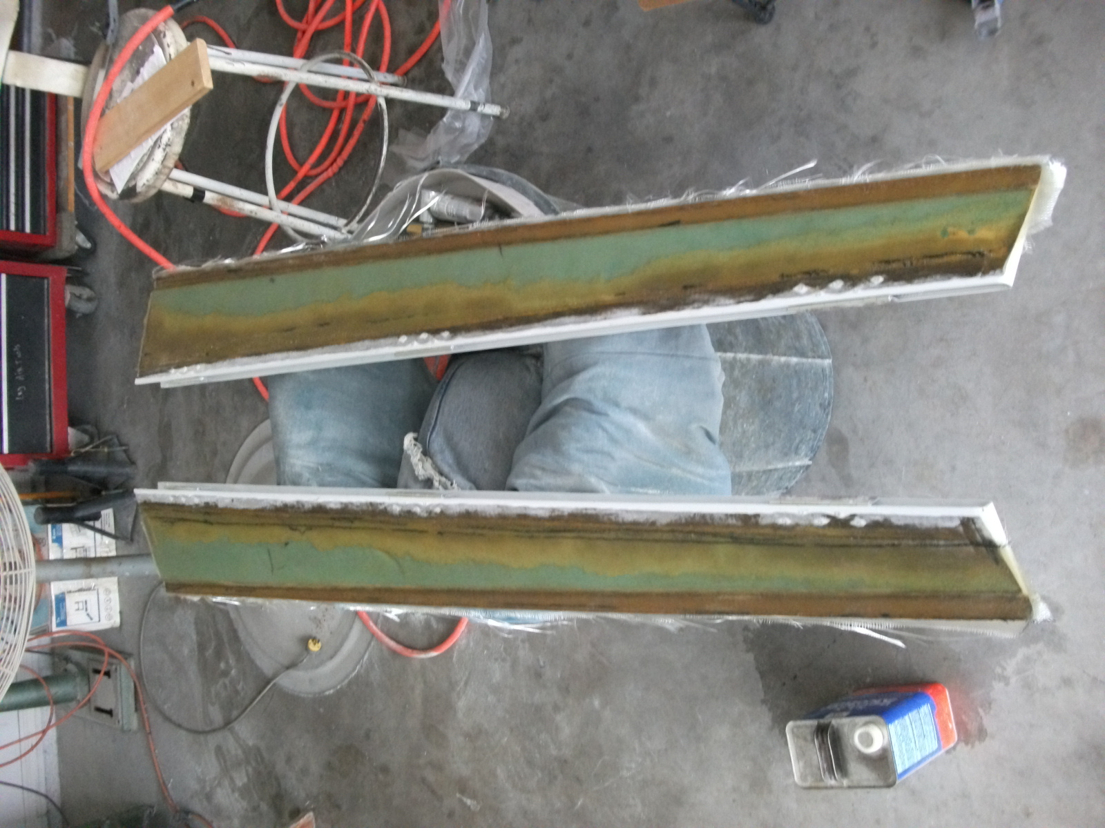
Here’s the rudder that was causing the flutter.
Eventually, Malcolm ended up sanding deep into the foam before the he could get the correct shape.
Covered with uni.
With filler. We now have a low spot on the outside surface.
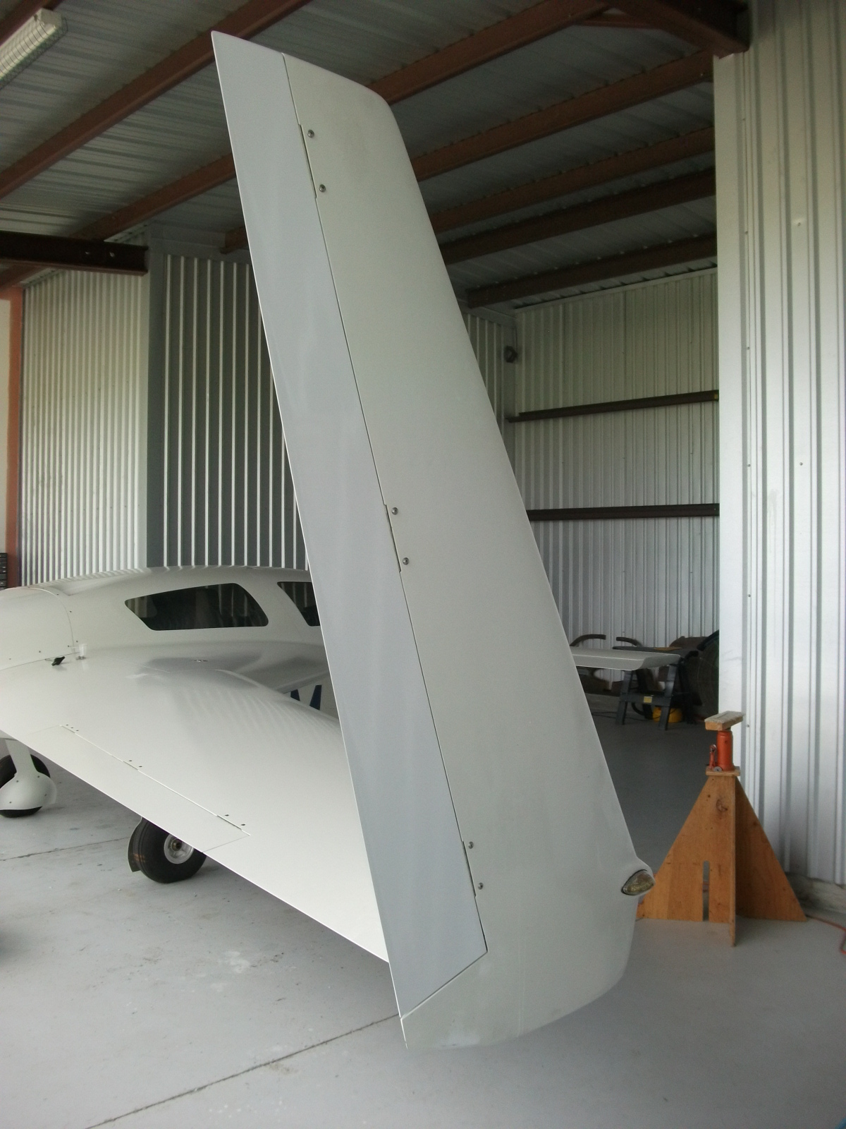
Painted and installed.
I didn’t want to try and install the roll trim because I wasn’t sure when Scott was going to be able to make another test flight.
On the Friday the 31st, Scott made test flight #4. The plane accelerated through 165kts with no flutter. He said that he got it up into the “170’s”, but the data log showed a max speed of 180kts. There was some scary weather approaching so the flight was cut short.
The next day, I installed the roll trim.
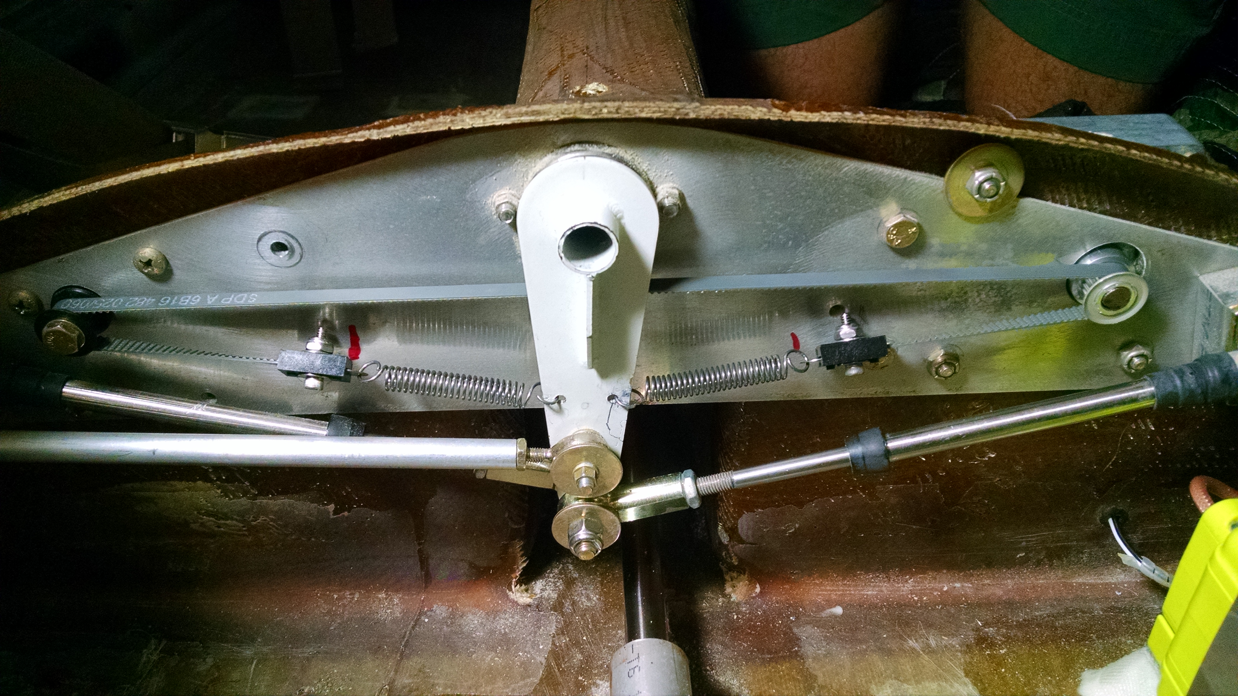
Here’s my roll trim mechanism.
Since I had originally intended to install roll trim, I had pulled all the wires, I just had to terminate them. Now for the pitch trim, I went with the TCW Technologies Safety Trim controller. I did this for a couple of reasons. The primary reason was that the Vertical Power VP-X trim driver is designed for low power RC Allen trim motors and is limited to 1amp. They don’t recommend using it to drive Velocity trim motors. The other reason I used the Safety Trim controller is that it has some really nice features:
Dual speed; it will drive the motor faster at lower airspeeds when large changes in trim are needed quickly while at high airspeeds, it drives the motor slower to prevent trim overshoot.
Runaway prevention; If the pitch trim switch should fail in the closed position, the trim motor will not continue to run. The controller will only allow the motor to run for about 3 seconds at a time. If you need more trim, you release the switch and then press it again.
Reversible; If the switch gets stuck, you can disable and reverse the motor with a switch on the panel.
So when I realized that I had to install the roll trim, I was thinking that I was going to have to buy and install another trim controller. But fellow builder Bob Holtaway did some testing and determined that the pitch trim pulled significantly less current that expected. And since the roll trim has much less load than the pitch trim, I decided to go that route instead.
Everytime I work with the VP-X, I’m amazed. Just about every aspect of it is well thought out and easy to use. Once I connected the wires, it took about 10 seconds to configure the VP-X to drive the roll trim motor. I had the trim motor wires reversed so it ran backwards. It took about 2 seconds to correct that in the VP-X configuration.
So at this point, the gear door flutter, rudder/winglet flutter and left roll have been resolved. I’m hoping that I don’t discover another surprise that rears it’s head at 190kts.
Lots of things going on. Because we sold our Chicago area house and bought a house in Panama City (literally on the same day), and said Panama City house needed a LOT of work before the planned move in date of 9/5, I haven’t had much time for airplane related activities. I did run down and get the roll trim installed but that’s about it.
Because I’ve only got 25 hours to fly off, I was planning on doing that in one trip. And to handle the transportation, my good friend Rody (who was in the plane when I had the nose gear collapse on the 182-RG in Greensboro, NC) suggested that I just rent a car and drive down then drop it off there if I can fly off the hours in one trip. Thanks Rody!
So I got a car from Enterprise (only nationwide car rental company with an office in Sebastian) and drove down on Sunday, September 13th. Then I got John Abraham to go up with me for a couple of quick take off and landings. Remember, I only have 5 hours in Velocities and that was the small trainer that’s fixed gear.
So we hopped in the plane and took off.
Holy crap, this this is FAST! Rocketed down the runway, lifted off and before I knew it the we were at 130kts and climbing… rapidly. Then the “Low Oil Pressure” light started flashing. A quick check of the gauges showed the oil pressure was reading right where it should. So we stayed in a tight pattern just in case. After a minute, the light went out. It turned out that I had inadvertently set the alarm (which drives the “Low Oil Pressure” light) to indicate for low oil pressure and if a cylinder head temperature exceeded 400 degrees. Oops.
The two landings were far from impressive. Long with lots of over-corrections.
Then I was up on my own. I decided to fly south to Stuart (the south end of my test area) and then back north to Sebastian. This takeoff was even more… exhilarating. With just me in the plane it accelerated like a sports car. In no time I was at 1,500 feet and climbing in excess of 1,500 feet per minute.
Lots of challenges here. First is staying in front of the plane. I ran into this challenge when I moved from flying fixed gear Cessna 172’s to my 182-RG. Lots more power and lots more speed. Eventually you start thinking far enough ahead that you’re playing “catch up” all the time.
The other challenge is migrating from “steam gauges” to a glass panel.
Here’s the panel I’ve been flying behind for the past 16 years.
If you’re not a pilot, it may seem daunting, for me it’s been home for the last 16 years. Airspeed? Top left. I haven’t really looked at anything other than the needle position for a long time. When I’m on base leg, the needle is about 3 o’clock. Over the runway for landing, 2 o’clock. Vertical speed? directly over the yoke. Hard to miss being level or in a 500fpm climb. Altitude? Directly above the VSI. It’s second nature.
Now…
So now when I need to know how fast, there’s no needle. Just to the left of center is a vertical tape with (in this case) 165 in the middle. That how fast I’m going (indicated, not actual). Altitude? To the right of center. I’m at 6,510 feet. Vertical speed? On the left side of the altitude tape are some hash marks that angle up and down. If I was climbing at 1,000fpm, the area from the middle to the “1” would be shaded. For a non-pilot that hasn’t been looking at the old six-pack or steam gauges, this probably makes perfect sense. But I’ve been flying behind those old gauges for so long that this will take some getting used to.
Yesterday, I arrived at my home field with the Velocity. Seven and a half years after making the first fiberglass layup.
Weather was tricky as there were showers and clouds between Sebastian and Orlando that I had stay clear of (there is currently no weatherstripping and the plane is not certified for IFR). But once past Orlando is was a clear shot to Panama City.
Two highlights were having Tampa approach pointing me out to a passing Delta flight (“Delta 123, you have a Velocity off your right at 6,500”). I couldn’t figure out why a 767 would be so low or why they never called my to tell me about the Delta flight. Then I noticed they were at about 18,000′. That was cool.
Then I passed a Skylane like it was standing still. That was fun.
Arriving at my home field it was empty. I figured Ann would be waiting for me so I gave her a little show. I did a low approach and overflew the runway. I had to pull the power way back because it was really bumpy.
I had been wondering how visibly the flashing landing lights would show up. She said that she could see me coming for a long way off.
Video of the low approach and landing (apologies for the portrait mode… what are you gonna do?).
I’ve got some other posts that precede this one but I wanted to get this up ASAP.
One of the tasks during Phase I flight testing is to determine the significant flight speeds. Things like Vx (best angle of climb), Vy (best rate of climb) and Vso (stall speed in landing configuration).
Stall speed is easy… especially in the Velocity. Just keep going slower and slower until the canard stalls.
The climb speeds were a bit of work though. Basically you pick a starting altitude (I chose 4,000′) and then get into a full power climb at a defined airspeed before hitting that starting altitude. Then hold that airspeed for one minute and see how much altitude you gained.
Repeat for at least four airspeeds. I chose 70, 80, 90 and 100kts. Then take those results and plot them on a graph. On most conventional aircraft you end up with a pretty bell curve. The peak of the curve is your best rate of climb. Then you draw a line from 0/0 to where it just meets the curve and the point it touches is your best angle of climb.
Normally, it looks like this:
It this example, Vy would be about 86kts and Vx would be 80kts.
But the Velocity is anything but normal.
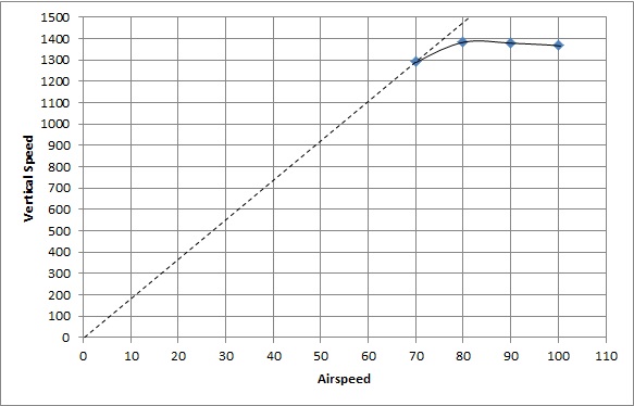
Here’s the chart I ended up with:
Not exactly what you would call a bell curve, huh?
For Vy, 80kts gave me the best rate of climb at 1,386fpm. But there’s almost no forward visibility at 80kts since it feels like you’re looking straight up. And it’s about 20kts above the canard stall. And finally, 90kts is only 10 feet per minute slower. 100kts is only 4fpm slower than 90kts. So I like 90kts as Vy.
Vx is real tough. I could run another flight test and see where 60kts comes in on the graph, but I don’t think I would like the deck angle or being that close to the stall speed at that angle. So I would be happy saying that Vx is 70kts.
Except that I don’t like the idea of flying at that angle. And because I have all the data being recorded, I was able to determine the deck angle and the distance covered during the climb. The deck angle really isn’t significant since what you’re really trying to do is get as high as possible over a given distance. What I discovered is that the distance covered for 1,000 feet of altitude gained is:
While 70kts is obviously a better climb angle, 80kts provides the same altitude gain with only an additional 80 feet of distance.
So for me, 80kts is now the official Vx.
And if I’m ever in a situation where I REALLY need to get higher in the shortest possible distance, I know that 70kts will get me over that mounding pile of zombies. I just need to watch the CHT’s and make sure I don’t get any slower.
Even though this was done during Phase I Flight Testing, I wanted to lay the groundwork for some recent testing.
Foreflight recently added a feature where it draws a line around the plane that shows how far you can glide (it factors in terrain and winds). In order to use this, you have to know the glide ratio. During Phase I, I figured the best glide speed (basically, minimum sink rate), but didn’t know what the glide ratio was.
I did some research and discovered what glider guys have known for years. The Polar Glide Chart. Basically, this is the same chart that I used to determine the climb speeds. It’s just inverted. Now the glider pilots take this way deeper than I need to go, but the concept is the same. Pick a starting altitude, fly a decent at a constant speed, then after 1 minute record the altitude lost. Go back up and repeat at another three airspeeds. I used 5,000′ as my starting altitude and 100, 90, 80 and 70KIAS for airspeeds. Like I did with the climb tests, I did all the descents in the same direction in roughly the same place, this way I could use the flight data recorder to also determine distance.
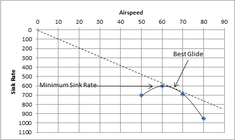
Here’s what a chart would look like for a traditional airplane:
Here we can see the airspeed which gives you the minimum sink rate (or most time in the air) is about 62kts. The airspeed which would provide the greatest distance looks to be about 65kts. I can’t find any official designations for these airspeeds. I’ve found Vld which is supposedly the best “Lift to Drag ratio” so that sounds like minimum sink rate. And I’ve seen some references to Vbg which is supposed to be “Best Glide”. So I’ll use those. If anyone knows the official terms, please let me know.
Now for the results of my recent testing.
Not very different from the climb chart.
In this case, the sink rate decreases the slower you fly but starts to flatten out at about 70 knots. But it’s not about staying in the air longer. You also need to cover ground.
For distance, it looks like about 88kts would give the best glide distance at 12.15:1.
So in the interest of simplicity, I’m going to call 90kts Vbg.
Now in the real world, if the engine ever stops, the glide ratio will increase since there will not be the drag from the windmilling prop. Not sure how much it will improve the ratio, but more is usually better, right?