
- 6.5.2 – Rudder Pedals
- 6.7.1 – Spar Positioning
- 6.1.5 Keel Hardpoints
- 6.8.1 – Canard Reinforcements
- 6.1.3 Keel Access Holes
- 6.2.3 Front Seats
- 6.3.1 Assemble Rudder Pedals
- 6.3.1 Brake Lines
- 6.3.1 Brake lines
- 6.3.1 Brake Lines
- 6A.3.1 Toe Brakes
- 6A.3.1 Parking Brake
- 6.6.2 – Install Landing Gear Selector
- 6.2.2 Safety Harness Hardpoints
- 6.9 Overhead Fresh Air Plenum Modification
- 6.9 Overhead Fresh Air Plenum Installation
- 6.3.7 Keel Installation (prep)
- 6A.3.1 Rudder Pedal Assembly
- 6.3.7 Keel Installation
- 6.7.2 Main Spar Installation
- 6.7.3 Main Spar Triax Layups
- 6.2.1 Seat Hardpoints
- 6.1.2 Keel Access Cover Flanges
- 6A.3.1 Rudder Pedal Installation
- 6.6.2 Install Instrument Panel
- 6.2 Assemble Seats
- 6.8 Doghouse Edge Finishing
- 6.8 Canard Reinforcements
- 6.8.2 Doghouse Attach Points
- 6.5.4 Install Nylaflow Tubing for Rudder Cables
- 6.3.7 Install Aft Keel Section
- 6.9 Overhead Plenum Lights
- 6.0 Aft Carbon Beam (Remediation)
- 6.9 Overhead Fresh Air Plenum
- 6.9 Overhead Fresh Air Plenum Painting
- 6.0 A-Pillar Beam (Overhead Switch Panel)
- 6.3.2 Front Seat Assembly
- 6.3.2 Front Seat Rails
- 6.3.2 Seating modifications
- 6.2.2 Safety Harness Replacement
- 6.2.2 Safety Harness Replacement
- 6.3.2 Seat rails and hardpoints
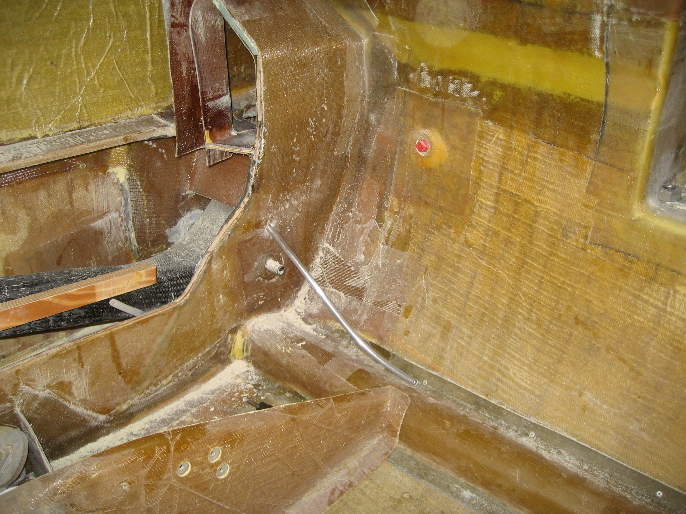
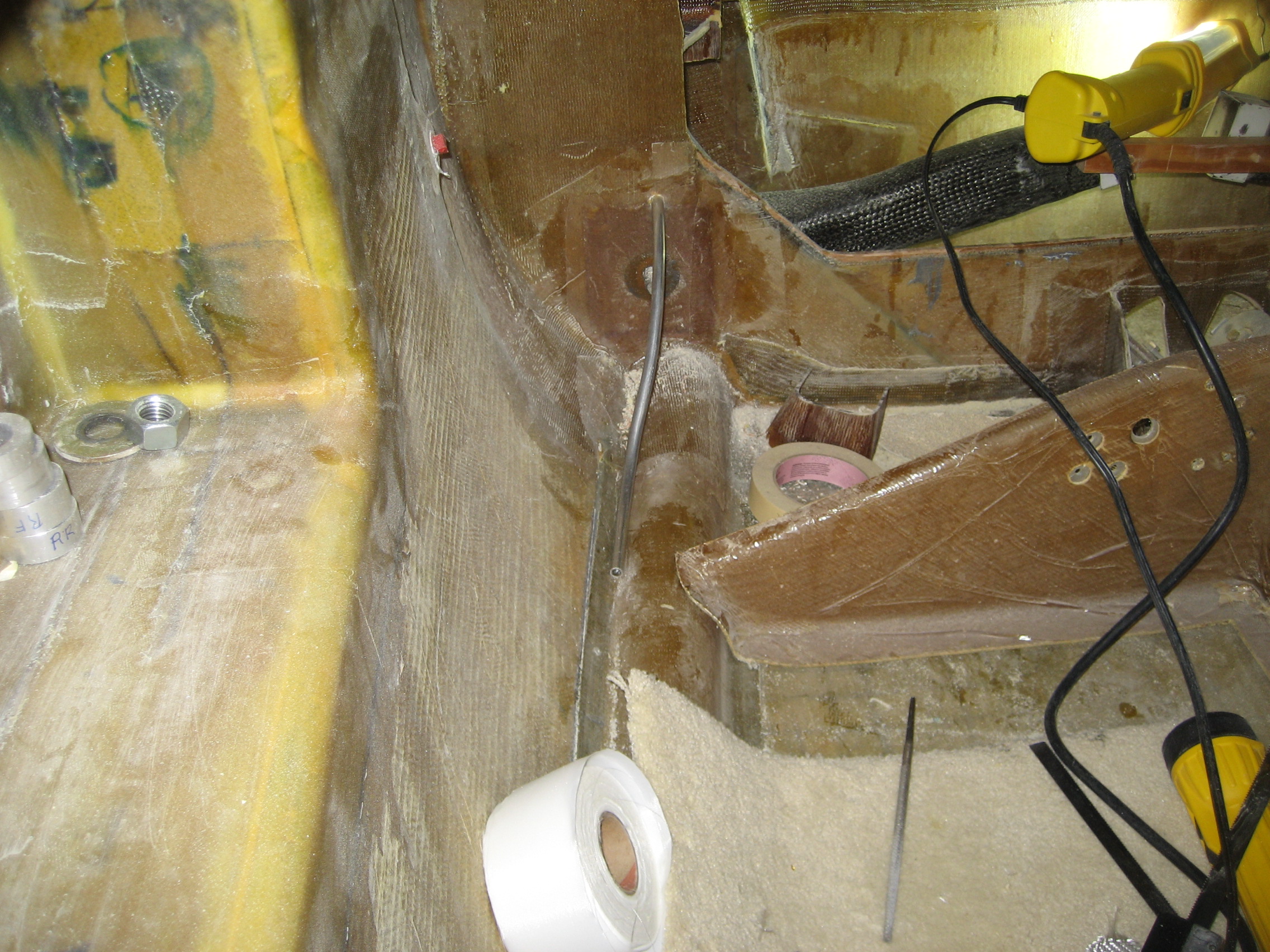
The rudders (one of each winglet) are activated by cables that go from the rudder pedals to the back of the fuselage and then out the wings to the winglets on the end of the wings. On my Cessna those cables get from the pedals to the rudder by means of numerous pulleys. On the velocity, the cables go through a nylon tube (Nylaflow) down each side of the fuselage near the floor. The tubing is glassed in place. But at the rear of the fuselage, it has to transition from the floor to penetrate the gear bulkhead about 12″ above the floor. During operation, this unsupported tubing can flex and make for slop in the feel of the rudders. Another Hangar 18 solution is to support the nylafow tubing between the floor and the gear bulkhead by putting inside a short length of aluminum tubing.
Here’s the tubing on the left side. I haven’t pulled the nylaflo yet but it will go inside the aluminum tubing.
Right side
And here’s the finished product. nylaflo tubing installed and covered with a layer of BID.

Closeup of the aluminum tube where the nylaflo goes in.
