- 6.5.2 – Rudder Pedals
- 6.7.1 – Spar Positioning
- 6.1.5 Keel Hardpoints
- 6.8.1 – Canard Reinforcements
- 6.1.3 Keel Access Holes
- 6.2.3 Front Seats
- 6.3.1 Assemble Rudder Pedals
- 6.3.1 Brake Lines
- 6.3.1 Brake lines
- 6.3.1 Brake Lines
- 6A.3.1 Toe Brakes
- 6A.3.1 Parking Brake
- 6.6.2 – Install Landing Gear Selector
- 6.2.2 Safety Harness Hardpoints
- 6.9 Overhead Fresh Air Plenum Modification
- 6.9 Overhead Fresh Air Plenum Installation
- 6.3.7 Keel Installation (prep)
- 6A.3.1 Rudder Pedal Assembly
- 6.3.7 Keel Installation
- 6.7.2 Main Spar Installation
- 6.7.3 Main Spar Triax Layups
- 6.2.1 Seat Hardpoints
- 6.1.2 Keel Access Cover Flanges
- 6A.3.1 Rudder Pedal Installation
- 6.6.2 Install Instrument Panel
- 6.2 Assemble Seats
- 6.8 Doghouse Edge Finishing
- 6.8 Canard Reinforcements
- 6.8.2 Doghouse Attach Points
- 6.5.4 Install Nylaflow Tubing for Rudder Cables
- 6.3.7 Install Aft Keel Section
- 6.9 Overhead Plenum Lights
- 6.0 Aft Carbon Beam (Remediation)
- 6.9 Overhead Fresh Air Plenum
- 6.9 Overhead Fresh Air Plenum Painting
- 6.0 A-Pillar Beam (Overhead Switch Panel)
- 6.3.2 Front Seat Assembly
- 6.3.2 Front Seat Rails
- 6.3.2 Seating modifications
- 6.2.2 Safety Harness Replacement
- 6.2.2 Safety Harness Replacement
- 6.3.2 Seat rails and hardpoints
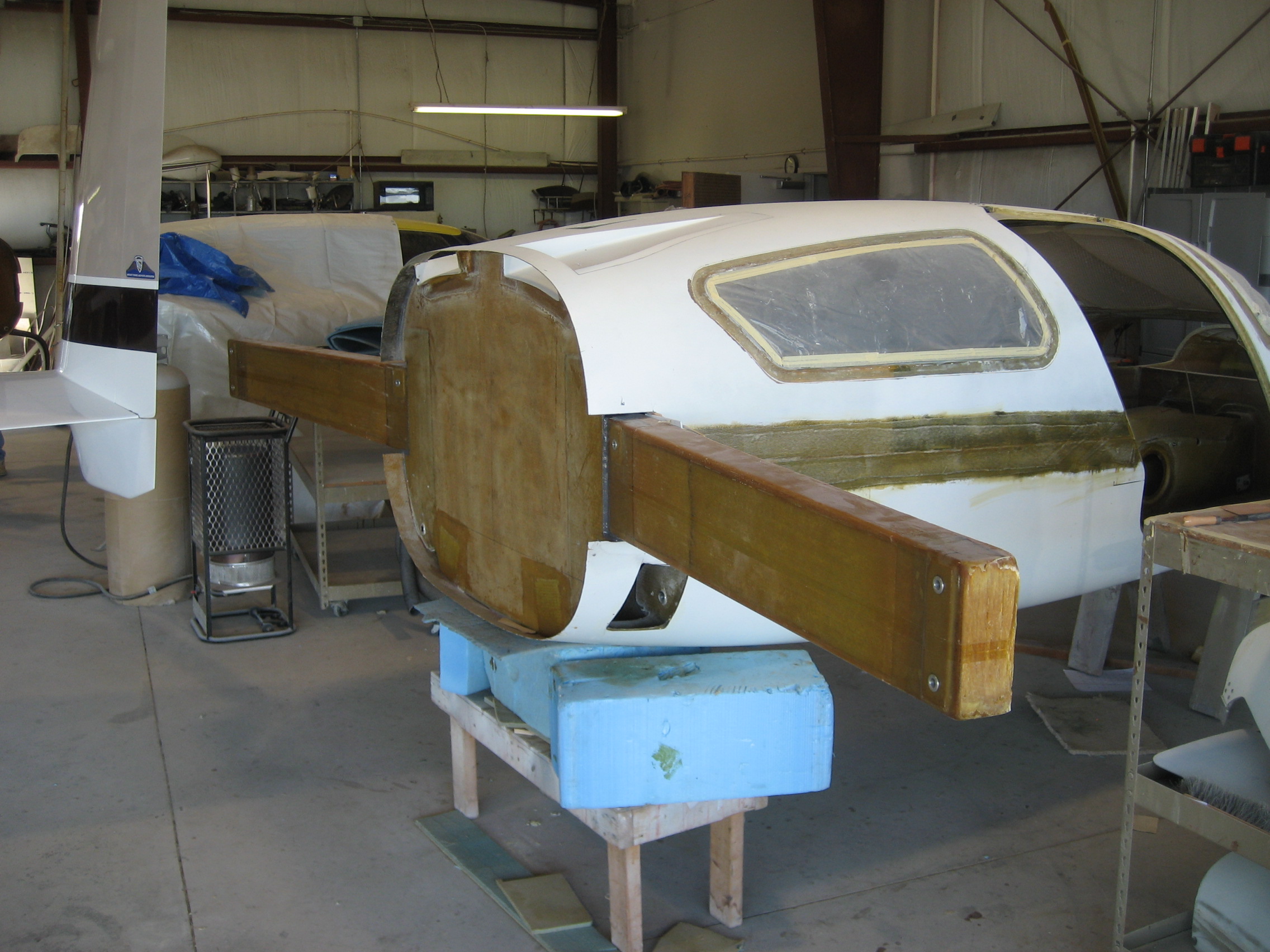
Prior to installing the spar, the airplane is leveled (precisely) side-to-side and front-to-rear.
Normally, the spar is installed before the top fuselage is mated to the bottom. But in a fastbuild, the factory joins the two fuselage parts. This makes installing the spar… challenging. I had previously cut holes in the rear of the fuselage to accept the spar. First the spar is slid through the fuselage to check the position. Since the wing is mounted to the spar, the position of the spar is CRITICAL. First it is checked for center. It must extend out the fuselage equally on both sides (you wouldn’t want one wing longer than the other, right?). This is pretty easy; just measure each end to the center of the firewall. A nudge, measure, a nudge, measure, etc. Then it is checked for level left-to-right. In this case a small shim was needed on the right side. Then the spar is checked for level front-to-rear. The spar was perfectly level in this direction. Finally, the spar is measured for perpendicular to the centerline. This is done by measuring from the nose of the plane to the left end of the spar and comparing it to the right. Both dimensions were identical! This is starting to make me real nervous. This have been about the forth thing that usually requires a bit of adjusting to make it true.
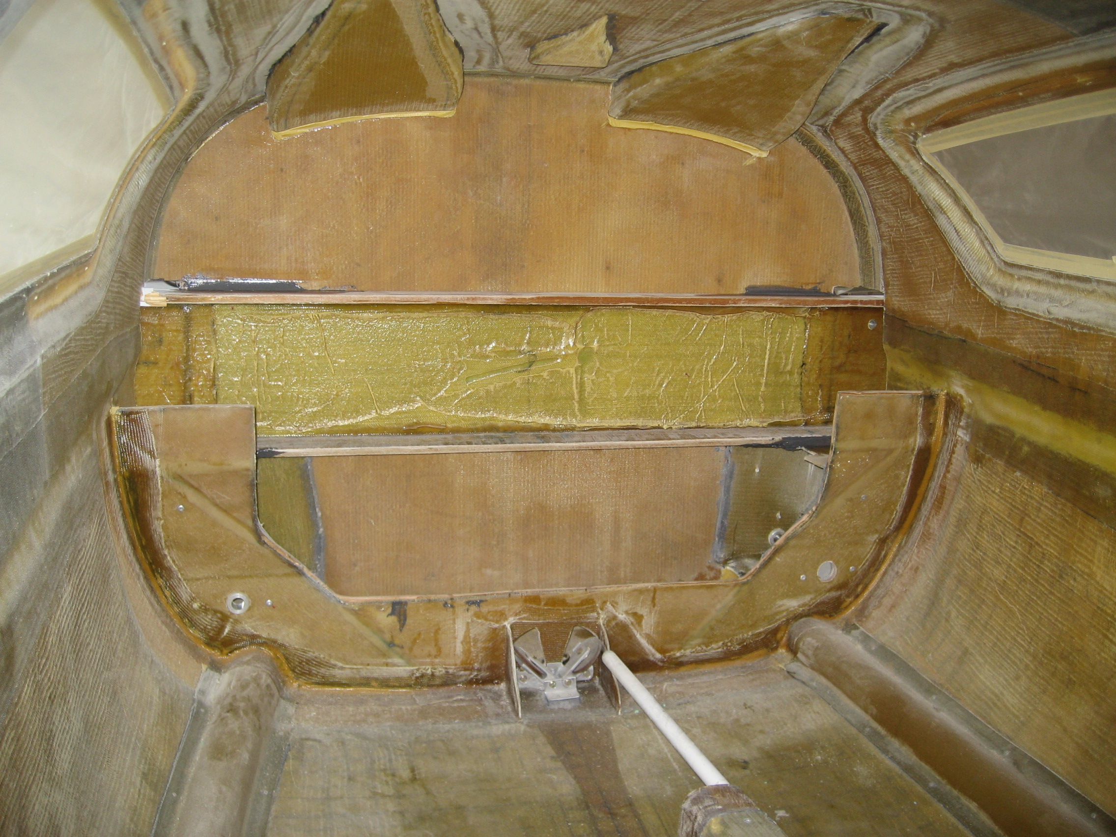
Then the spar is marked for position and removed. Structural adhesive is thickened and liberally applied. Then we slid the spar back in trying to not smear it all over the place. Once it was back in place we had to recheck all the measurements. It only required a couple of tweaks to get it back in the correct position.
Then it’s left to cure overnight.