
- 6.5.2 – Rudder Pedals
- 6.7.1 – Spar Positioning
- 6.1.5 Keel Hardpoints
- 6.8.1 – Canard Reinforcements
- 6.1.3 Keel Access Holes
- 6.2.3 Front Seats
- 6.3.1 Assemble Rudder Pedals
- 6.3.1 Brake Lines
- 6.3.1 Brake lines
- 6.3.1 Brake Lines
- 6A.3.1 Toe Brakes
- 6A.3.1 Parking Brake
- 6.6.2 – Install Landing Gear Selector
- 6.2.2 Safety Harness Hardpoints
- 6.9 Overhead Fresh Air Plenum Modification
- 6.9 Overhead Fresh Air Plenum Installation
- 6.3.7 Keel Installation (prep)
- 6A.3.1 Rudder Pedal Assembly
- 6.3.7 Keel Installation
- 6.7.2 Main Spar Installation
- 6.7.3 Main Spar Triax Layups
- 6.2.1 Seat Hardpoints
- 6.1.2 Keel Access Cover Flanges
- 6A.3.1 Rudder Pedal Installation
- 6.6.2 Install Instrument Panel
- 6.2 Assemble Seats
- 6.8 Doghouse Edge Finishing
- 6.8 Canard Reinforcements
- 6.8.2 Doghouse Attach Points
- 6.5.4 Install Nylaflow Tubing for Rudder Cables
- 6.3.7 Install Aft Keel Section
- 6.9 Overhead Plenum Lights
- 6.0 Aft Carbon Beam (Remediation)
- 6.9 Overhead Fresh Air Plenum
- 6.9 Overhead Fresh Air Plenum Painting
- 6.0 A-Pillar Beam (Overhead Switch Panel)
- 6.3.2 Front Seat Assembly
- 6.3.2 Front Seat Rails
- 6.3.2 Seating modifications
- 6.2.2 Safety Harness Replacement
- 6.2.2 Safety Harness Replacement
- 6.3.2 Seat rails and hardpoints
The overhead switch panel is the beam which joins the A-pillars across the top. Just like the B-pillar beam, I added a couple BID of carbon fiber inside and out to increase the strength. Next, I had to decide how to join it to the A-Pillars. Here you can see that it doesn’t quite line up.
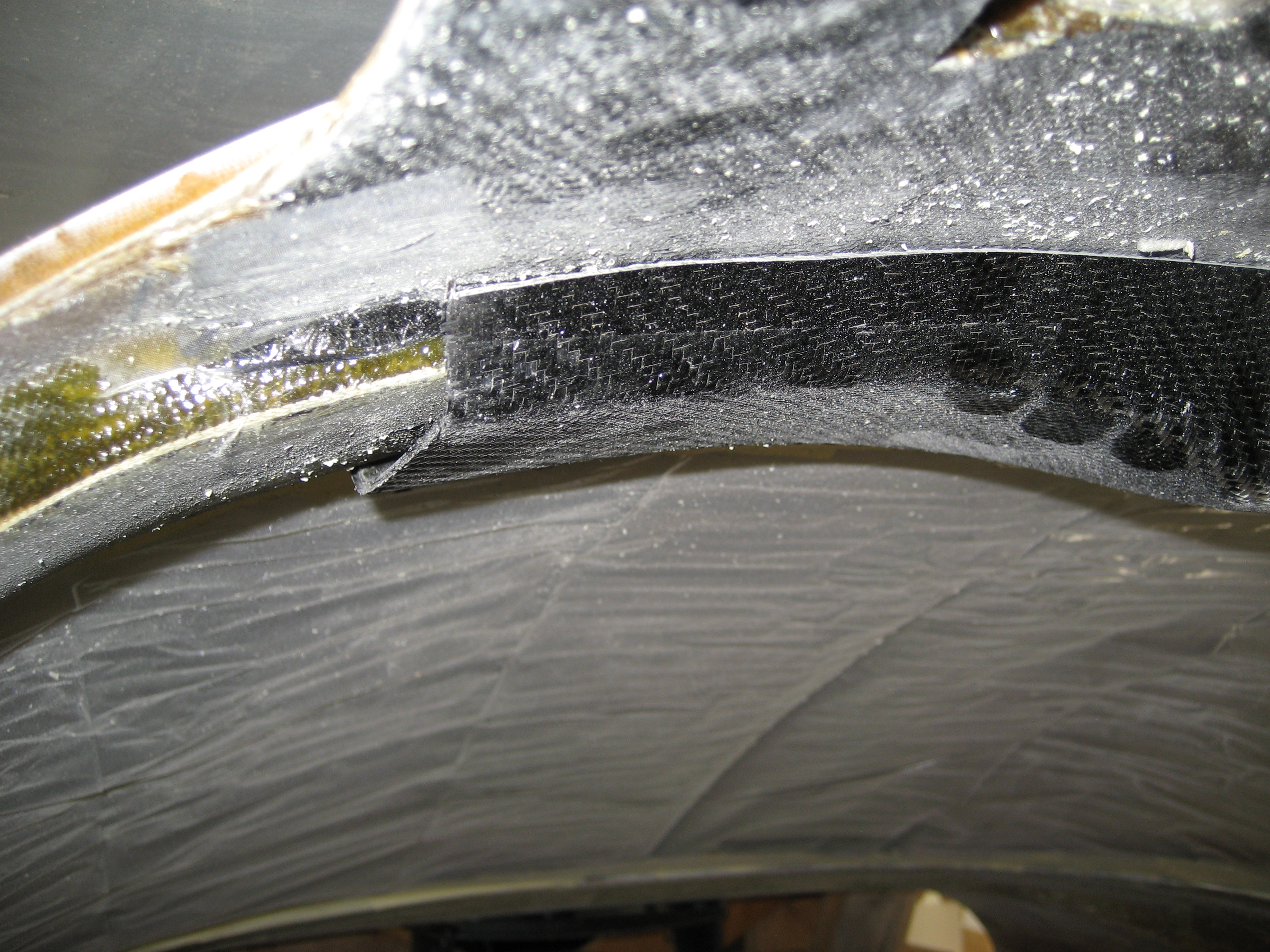
I could mount it as is and transition it or I could cut it down. As I’m taller than the average person, leaving it as is mean that it hangs lower. This COULD become a visual obstruction. It also means a bunch more work where it transitions to the A-pillar. On the down side to cutting it to fit is that I’ll have less room to work with when installing switches.
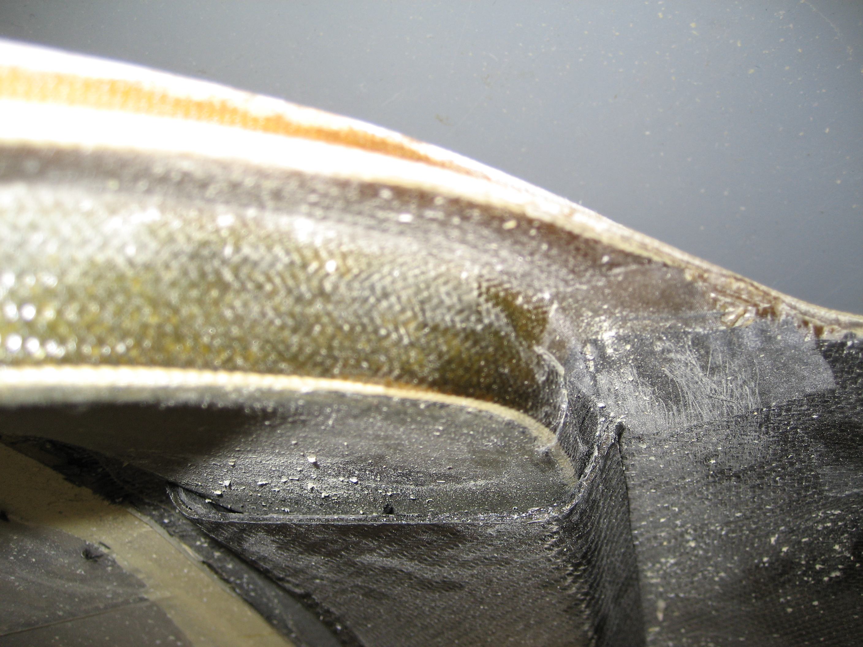
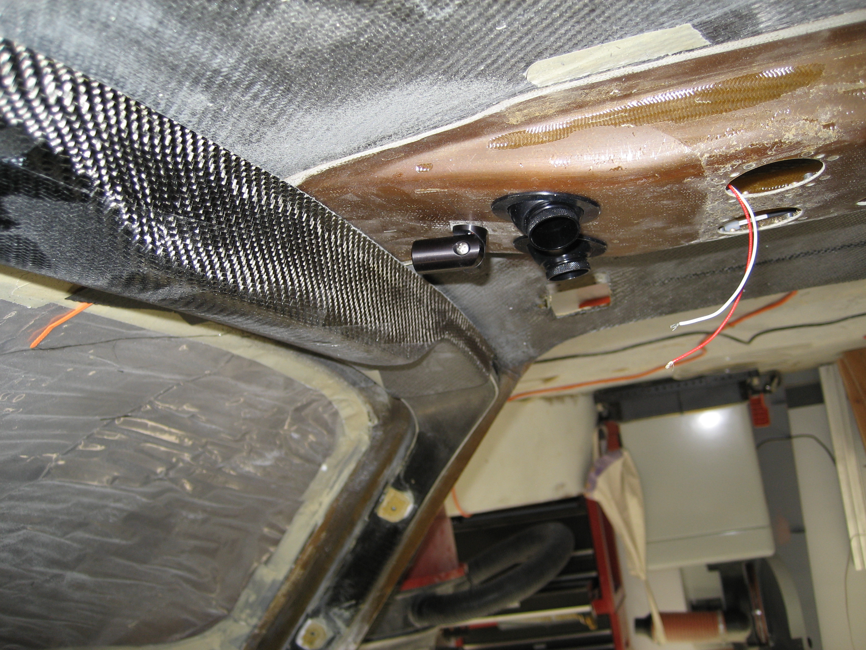
So I cut it down until if was even with the A-pillars. Then like I did with the B-pillar beam, I made a flange out of carbon fiber uni using the foam rubber trick. Here’s the result on the pilot side (the nylon tube is for routing wires).

Before permanently installing the beam, I needed to cut an opening and create a flange for where the switches would go.
Once again, here’s the beam before the opening:
And here it is after:

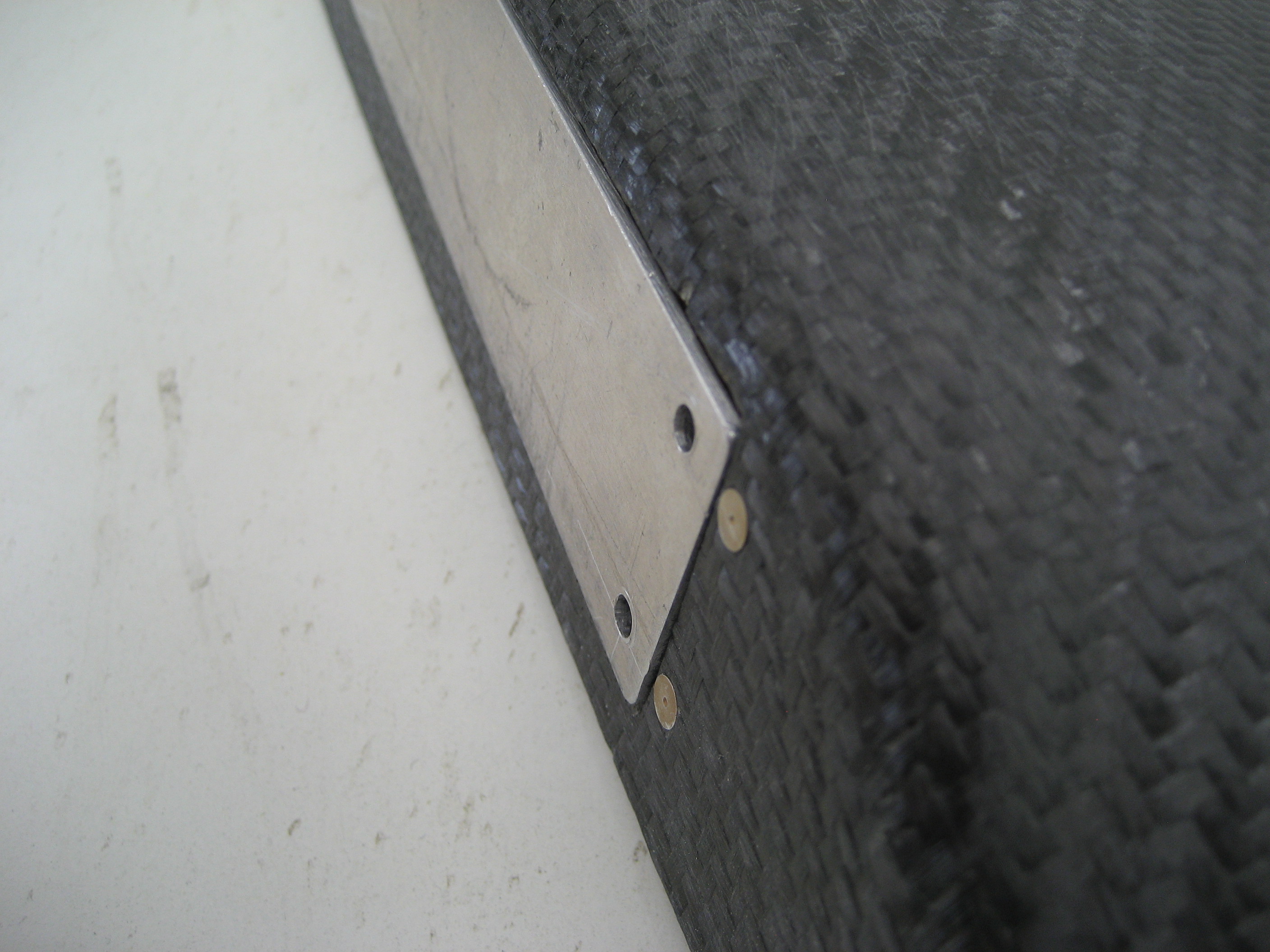
Closeup of the flange and nutplates:

With a blank aluminum panel in place:

Closeup of the panel:
To mount the beam, I used structural adhesive on the inside and a couple layers of carbon fiber uni on the outside of the seam and BID along the front and rear.
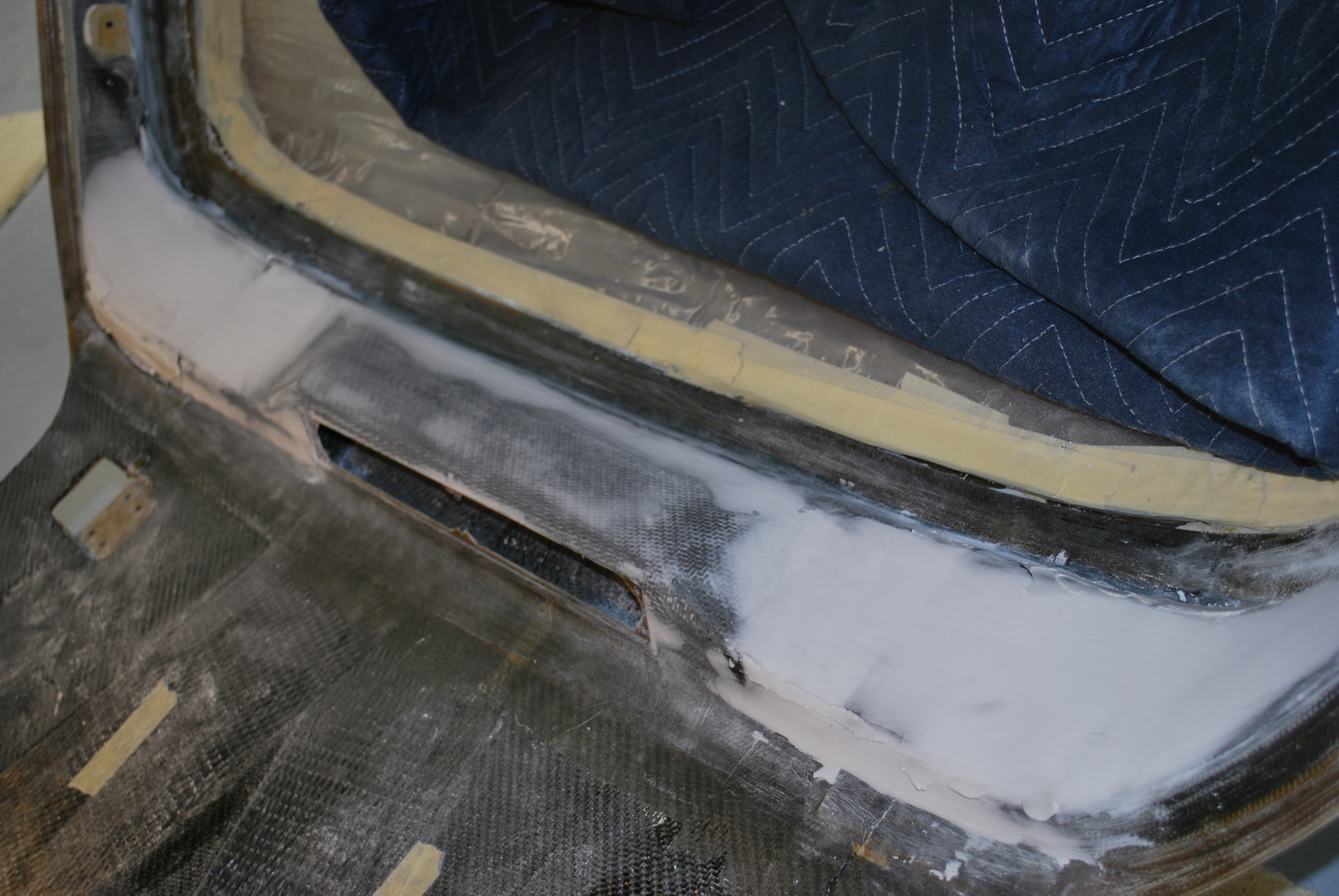
This is the beam after mounting and during filling.
Stuff you don’t think of until it’s (almost) too late.
Andy Millin came up with an absolutely brilliant thought. Rather than run the wiring for the plenum lights all the way from the front to the aft wall of the cabin, then up to the plenum, then forward to the lights; Why not create a tunnel between the inner and outer skin of the roof from the switch panel to the plenum? It’s only 4 inches instead of 20 feet! He did his BEFORE installing the overhead beam. But where there’s a will, there’s a way.
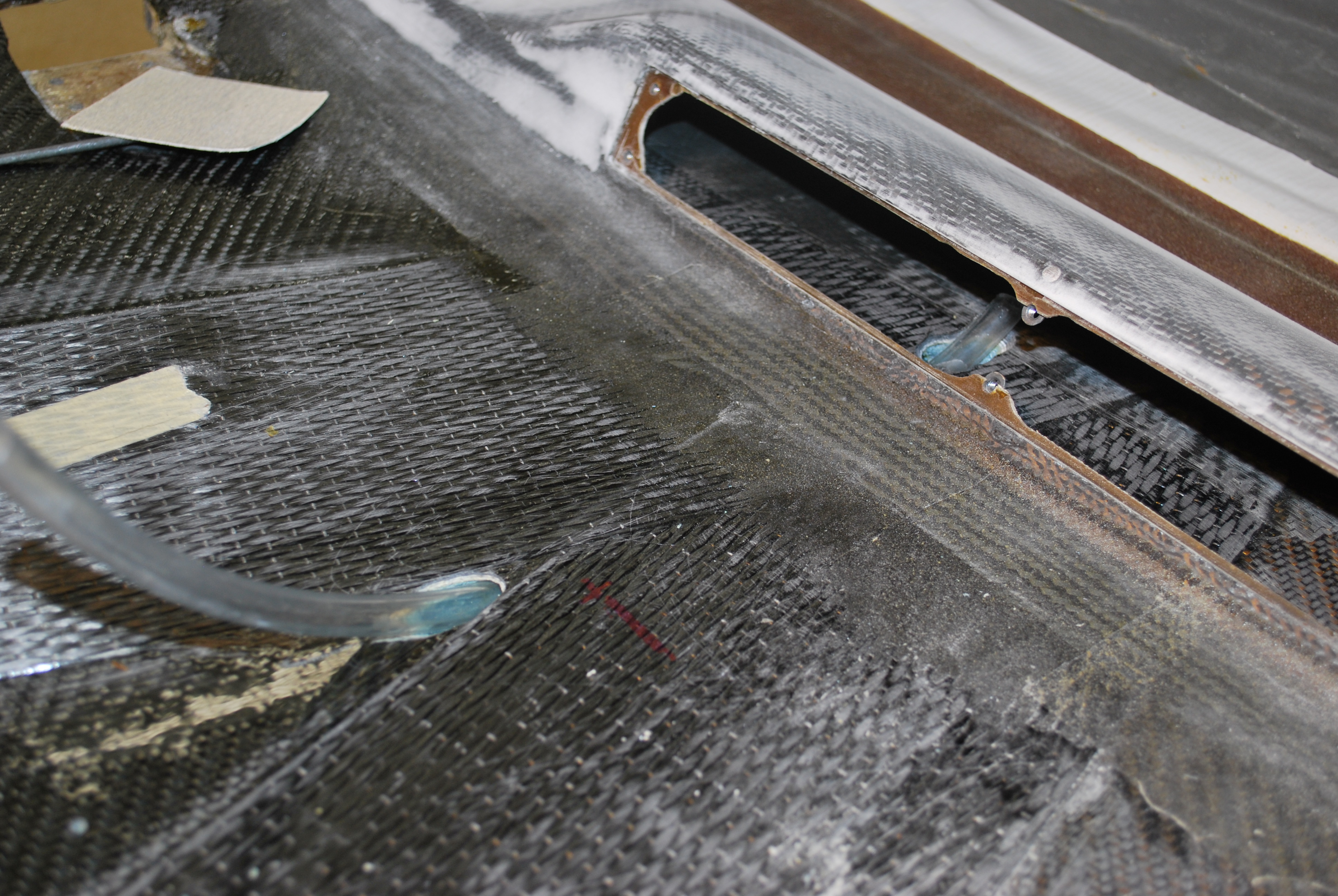
I drilled two holes; one where the forward edge of the plenum will be and the other behind the switch panel.
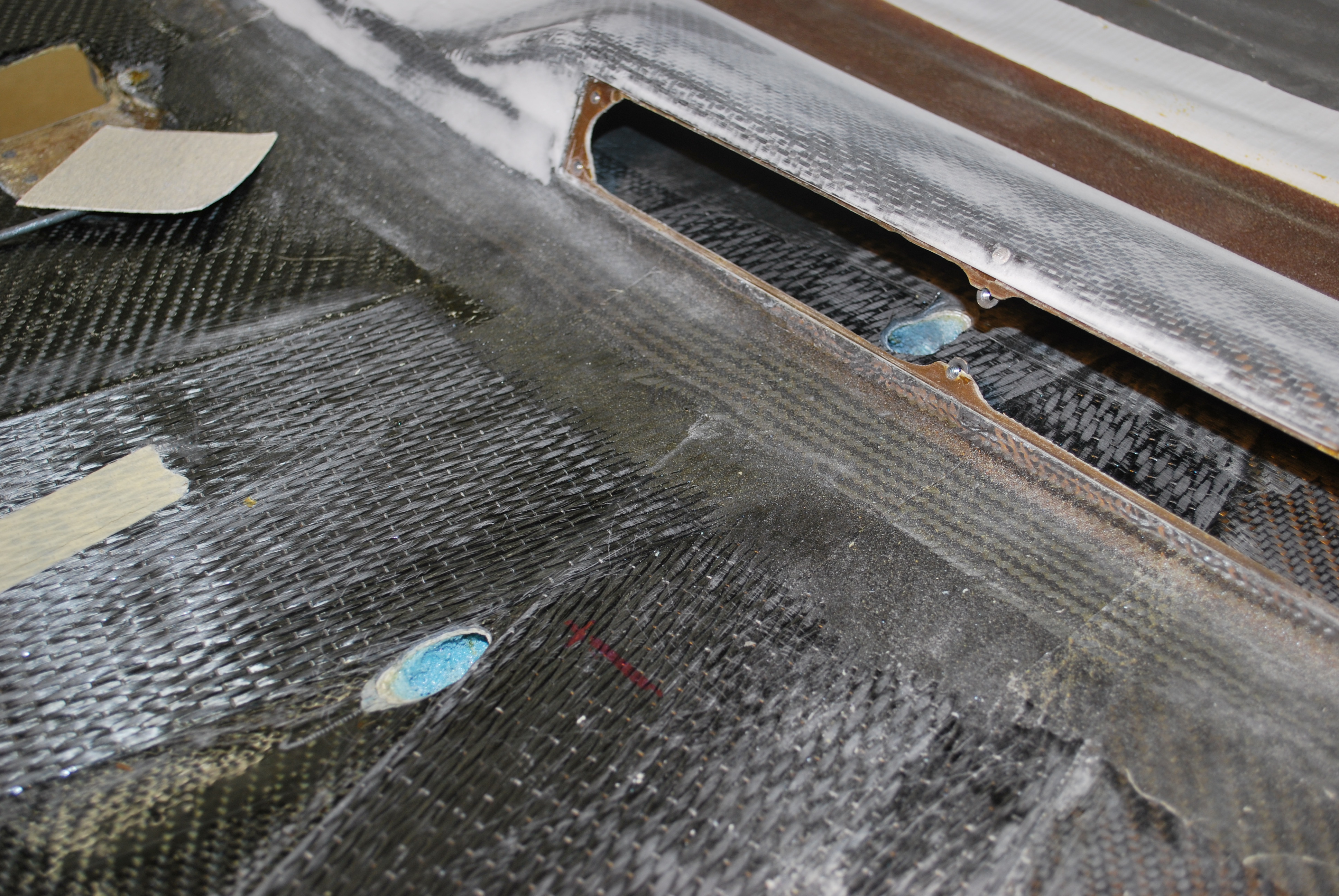
Then I started tunneling. Using a sharpened clothes hanger and some other MacGuyver-type tools, I was able to break though. Then I inserted at length of nylon tubing.
Then I filled the area around the tube with epoxy/micro.


Once the micro cured, I cut the tubing flush.