Nose gear spring replacement

This entry is part 37 of 39 in the series 07 - Landing Gear

Bouncing along on a amusement park ride.

That’s what one of my landings felt like. But it wasn’t my fault!  Runway 05/23 at Sebastian is not a very smooth runway.  Lots of dips.  On the above referenced landing, I hit one of these dips and got catapulted into the ceiling.  Now even with my seat and rail system modified, I don’t have much headroom… so at least I didn’t develop much momentum.

I think it was the day after that landing I was rolling up to the builders service center and Scott was watching me taxi up.  He had a very concerned look on his face.  Which was causing me to get a very concerned look on mine.

I shut down and got out and said “What?!?!”. He said “Something’s not right with your nose gear strut.”  Then he walked over and with one hand pushed down on the nose. When he did, the nose when down and the nose wheel sprung forward.  Then he said “This spring is too weak.  I shouldn’t be able to compress the spring at all.”

Normally, it would take a putting the weight of your whole body on the nose to begin to compress the spring.

At some point in the past, Velocity had some weak-ass springs. Scott asked what color my nose gear spring was. I told I wasn’t sure but I would check tonight. He said it felt like one of the white ones.  So I put the airplane away for the night and once back at the hotel, I looked through my pictures.

From January 25, 2008…

2008-01-25 1026 IMG_5873

Uh-oh.

The next morning, I taxied over to the Builders Service Center.  Scott was waiting.  “Well?” he asked.  I just shook my head.  He was visibly unhappy. “I thought that we found everybody that had a white spring and replaced them.”

He said the biggest danger is that when the spring compresses enough, the top of the gear is not supported against side loads.

Here’s a diagram that shows the nose gear assembly from the left side.

Nose Gear

This is showing the “Down and Locked” position. At the bottom of the nose gear is the wheel (out of the diagram, bottom left). At the top is the spring (in red). The blue “captivator” is a U-shaped steel bracket which prevents the top of the assembly from moving left to right. When weight is put on the nose of the plane, the spring compresses, the wheel moves up (and forward) and the top of the assembly moves back. If it’s just a little, it’s not a problem. If the top moves back enough, the top is no longer in the captivator.

The big problem with my weak-ass spring is that with just my weight in the pilot seat, the spring was already compressed some. Any bump (or another person in the front seat) and the spring is compressed enough so the top of the gear assembly is now out of the captivator. Which means a nose gear collapse is just a matter of time.

Scott then asked about my takeoffs. I told him the plane stays firmly on the ground until I pull up. He nodded and said “Yep. That’s what I figured.”  With the pitch trim set for takeoff but the spring compressed, the canard was not at the normal angle of attack. So it’s not creating any lift.  But once I pulled back on the stick just enough, the spring would uncompress, and the canard would then generate lift and the plane leaps off the ground.

So now what?

Scott said it’s not too bad of a job to pull the shock out.  So I started by removing the canard. Then it’s just the two bolts at either end of the shock.  It took me about an hour.

Then we rode over to the machine shop where Scott had already pulled a new (red) spring. With a special fixture for the press, the old spring was removed and the new one installed in about 3 minutes. Without a press, that would have taken me a whole day to figure out how to do that.

Another hour to put everything back together and Charlie Mike was ready to go. Total time, about 2.5 hours. That right there made the numerous trips back and forth between Panama City and Sebastian worth it.  If I hadn’t been there, Scott wouldn’t have noticed it. And I wouldn’t have since I didn’t have enough Velocity time to know that is was too soft.

The next takeoff was so much nicer. The plane literally flew off the runway. And the landing was so much better as well.

Static Port Conundrum

This entry is part 60 of 67 in the series 13 - Electrical / Instruments

The static port serves two primary functions: 1) It provides the ambient air pressure which the altimeter uses to determine the altitude. 2) It provides a reference pressure for the pitot tube to determine the airspeed.

The static port called out in the manual is built entirely by the builder.  I elected to purchase a pair of static ports from Aircraft Spruce similar to the static ports on my Cessna 182-RG.  The reason for having two is to correct the static pressure when the airplane is in a slip or skid. If the airplane is in a slip or skid and you have only one static port, then it could be in either a high pressure area or a low pressure area.

When I flew my plane (solo) for the first time, I was elated at the indicated and true airspeed. Indicated (IAS) is what the airspeed indicator shows and true airspeed (TAS) is your actual speed through the air.  To determine true airspeed, you take the indicated airspeed and compensate for temperature and altitude. The bottom line is that I was hauling ass!

But then I noticed my groundspeed. Normally when you’re flying, there’s either a headwind or a tailwind. If your true airspeed is 190 knots and there’s a 10 knot headwind, then you’ll only be traveling 180 knots over the ground.  But when I looked at my groundspeed while traveling south, it was showing about 20 knots slower than my TAS. Okay, I’ve seen 20 knot headwinds more times than I can count. After I turned around, my groundspeed was still about 20 knots slower than my TAS.

Now that’s peculiar.

The next couple of flights, I did a tests of the airspeed. This is accomplished by flying at least three different headings (usually greater than 90 degrees), noting the groundspeed on each heading and by using a formula you can determine your actual TAS along with the current wind speed and direction. What I discovered is that at cruise speed, the airspeed was reading about 25 knots faster than I was actually traveling.

But the slower I got, the closer the TAS got to the actual airspeed.

Now if it were reading slower than actual, that would point to a leak in the pitot system. But faster?!?!

After a lot of thought, I came to the conclusion that the static port must be drawing a vacuum. Since airspeed indication is a result of the pressure of the air being forced into the pitot tube compared against the static air pressure, it seemed likely that if the static pressure were less, the airspeed would read high.

I talked this over with Scott and Rick at the builders center. Scott said that he’s had to put “trip strips” in front of the static port to disrupt the air because it was pressurizing the port but he’s never had a static port effectively de-pressurizing before. He suggested putting a small piece of stir stick behind the port. This should stop the vacuum by pressurizing the port. Once it’s determined that was the problem, then the thickness could be adjusted.

So I taped over one of the ports (easier to test with one port), hot-glued a short length of stir-stick behind the static port and went for a flight.

Now the airspeed is reading about 15 knots low at cruise. This would seem to prove the concept.

But… if the static port were drawing a vacuum, then altitude would be showing higher than actual altitude (less pressure the higher you fly). And if the static port were being pressurized, then the altimeter would be indicating lower than actual.

This caused the hair to stand up on the back of my neck.  Because if I’m flying along at what I think is 6,500′ (westbound VFR altitude) and the static port is being pressurized, then I could actually be flying at 7,000′ (eastbound IFR altitude). But air traffic control would keep me from bumping into someone else, right?  Nope.  ATC thinks I’m at the altitude that my transponder is sending… which is what my static port pressure says it is… which is wrong.

So I got back on the ground to figure this out.

After talking with Rick and Dale (sounds like a 60’s surfer rock duo, doesn’t it?), I decided to build a manometer. AKA, pressure sensitive water level. So I removed the stir stick and hooked up my home made manometer.

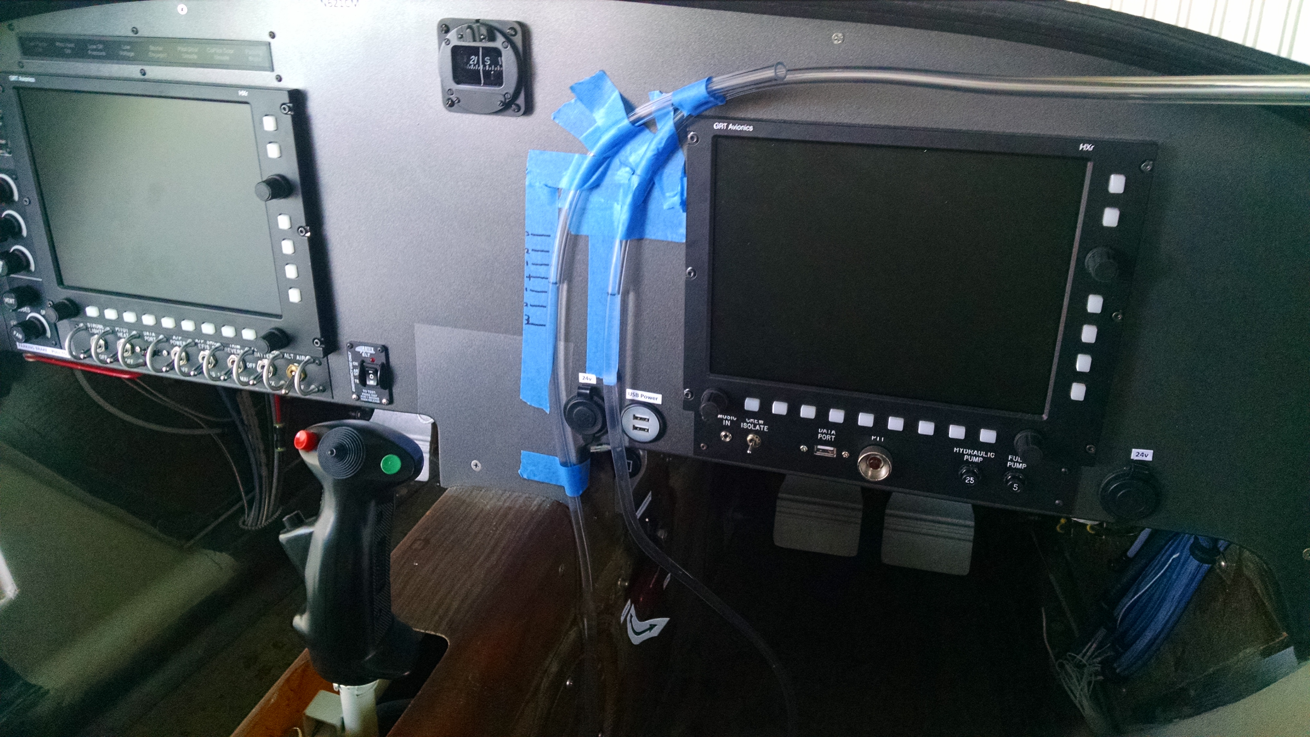
Here you go. Tell me that doesn’t scream “Experimental”.

IMG_20150925_132935362

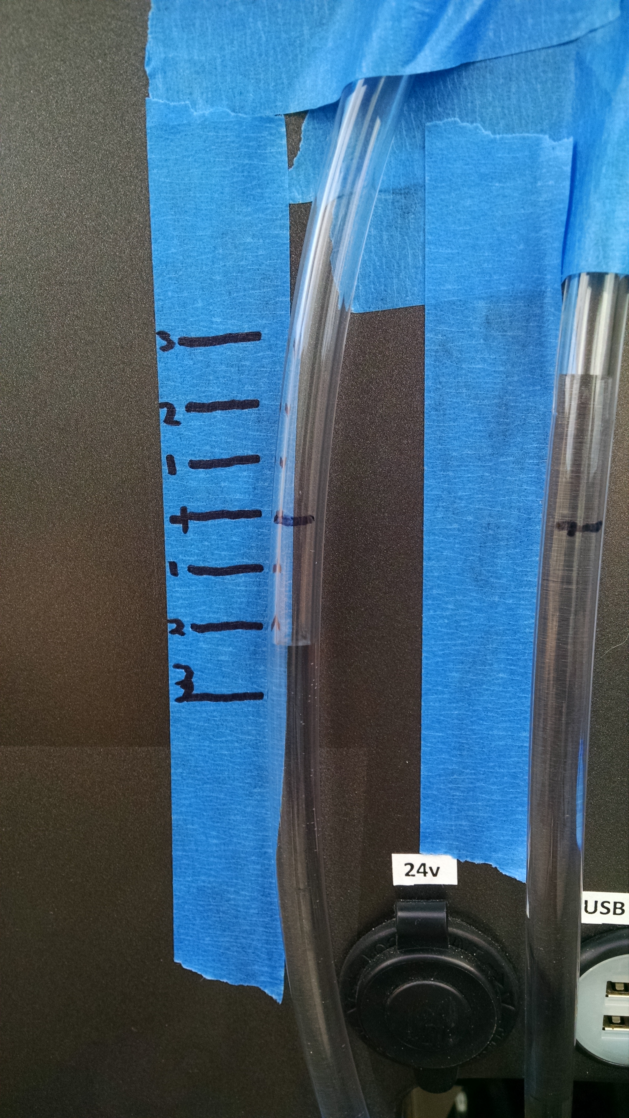
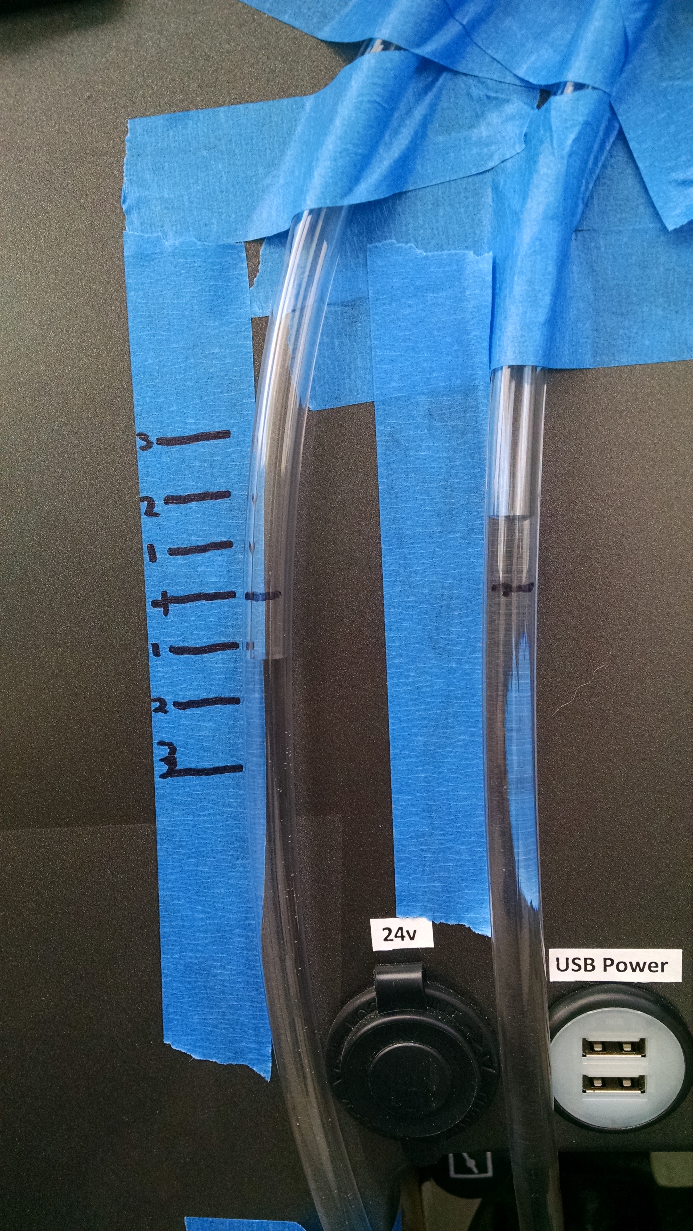
One end is connected to the static port (right tube), the other is open (if you already see the problem, you’re way ahead of me. But I figured it out at Sandy’s Grill over a cider that night).

Sitting on the ground, I made marks to show level and a few other reference marks. When air moves over the static port, if the water level in the left tube goes down, then the port is in a vacuum. If the level goes up, it’s being pressurized.

So here I am at 196 knots and 160 knots over the ground.

IMG_20150924_160551176IMG_20150924_161110900

Vacuum!!!

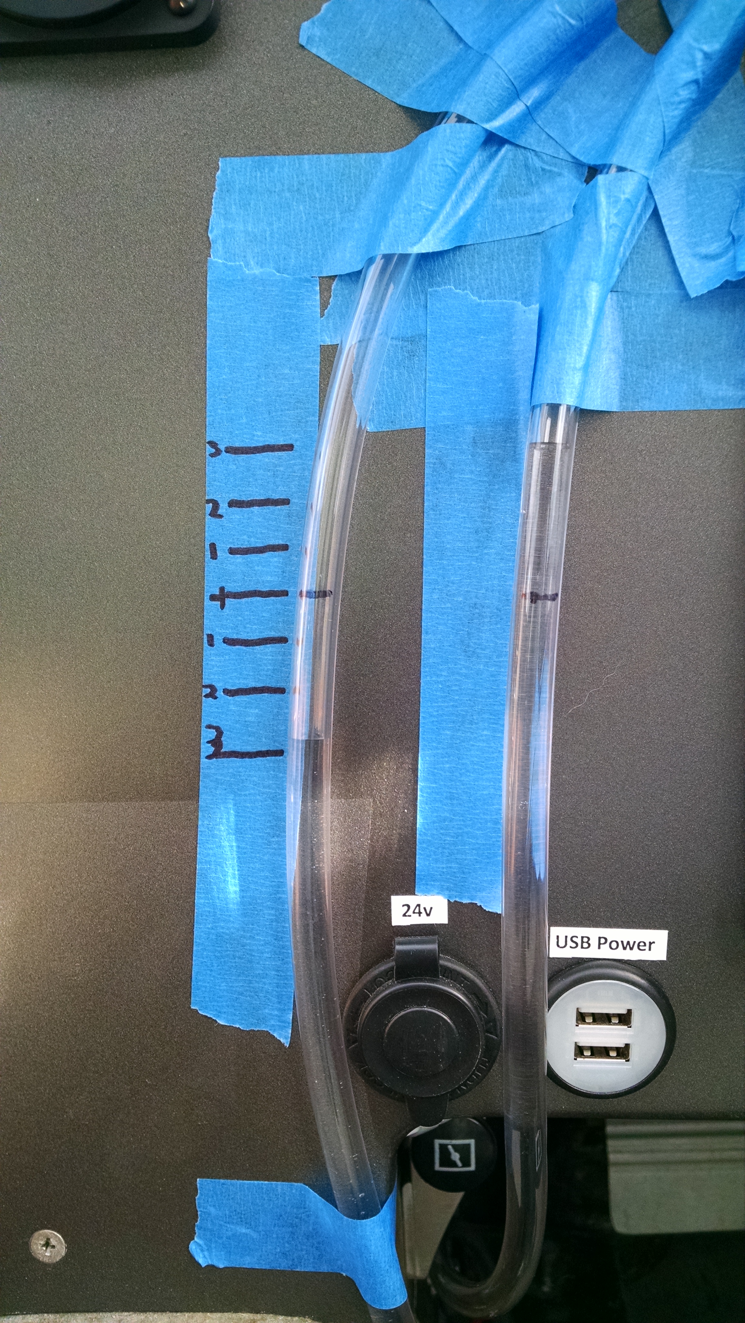
So I decided to change the shape of the static port from a flat disc to a dome (I’m obviously getting tired at this point) and went up again.

IMG_20150924_173357074

Even more of a vacuum!?!?

That’s when I decided to call it quits.

Because it was Thursday night, I went to Sandy’s Grill (Thursday is steak night there). While I was there thinking about things over a steak ka-bob and an apple cider, I had a couple epiphanies. The problem with the manometer is that it was measuring the static pressure relative to the pressure in the cabin. Which is typically lower than the outside ambient pressure to begin with and at this point is a completely unknown variable. Which means that was a pretty useless experiment to begin with.  The only way a manometer reading could be valid is if I could locate a true undisturbed ambient pressure location for the other end of  the tube.

Second was the modification to the static port. But making it domed shape, I effectively created an airfoil. Like the top of the wing. Which is a low pressure area. Which means it would be creating a vacuum. That is why it showed an even greater vacuum.

So I decided to approach it as simply as possible. There are two primary sensing instruments based on the pitot/static system: altitude and airspeed. If there are no leaks and the instruments are calibrated, then the only variables are the static port location and the pitot tube location. I was careful to locate the pitot tube where the manual specifies which obviously leaves the static port position as the problem.

So all I need to do is get one of those two instruments reading correctly and the other will have to be correct. Because I can’t determine my altitude with any accuracy (without something like a radar altimeter), then I’ll just have to tweak the static port until the airspeed reads correctly. Once the airspeed is showing the correct speed, the altimeter would have to be accurate as well.

Now this makes some pretty big assumptions. I didn’t skimp when I purchased the pitot tube (it cost me about $500) so I’m comfortable it should be creating the correct ram air pressure. I checked the system for leaks so I know that’s good. The last variable is whether the GRT Air Data Computer/Attitude/Heading Reference System (AHRS) is correctly computing the airspeed. The AHRS is a rather complicated piece of electronics and at this point I have to trust it’s doing it’s job.

And finally, since the changes I’ve made to the static port created variations that are expected predictable, then I’m confident that’s where the adjustments need to be made.

So I removed the static port, got a file and started filing down the leading part of the port. I only took able 1/16″ of an inch off (right is facing the front of the airplane).

IMG_20150924_183745396

Then I hooked it up and went flying.

When I crunched the numbers, the indicated airspeed was about 15 knots high.  I made a couple more passes with the file and did another flight. Now it was reading about 10 knots high.

So next I’ll make a couple more passes with the file and try again… and again… and again.  Basically sneaking up on it because I don’t want to go to far. When I get it to where the TAS equals the groundspeed (compensated for winds aloft), then the altimeter should be reading correctly as well. The only way that I can think of to test that is to make a high-speed low pass at the airport. If I do that at a visual height of 50 – 100 feet, then the altimeter should show that I’m flying at the field elevation plus 50-100 feet.

But for now, that will be one of the first things I do when I get back to Panama City.


First Flight! (for me)

This entry is part 6 of 7 in the series 16 - Flight Testing

Lots of things going on.  Because we sold our Chicago area house and bought a house in Panama City (literally on the same day), and said Panama City house needed a LOT of work before the planned move in date of 9/5, I haven’t had much time for airplane related activities. I did run down and get the roll trim installed but that’s about it.

Because I’ve only got 25 hours to fly off, I was planning on doing that in one trip.  And to handle the transportation, my good friend Rody (who was in the plane when I had the nose gear collapse on the 182-RG in Greensboro, NC) suggested that I just rent a car and drive down then drop it off there if I can fly off the hours in one trip. Thanks Rody!

So I got a car from Enterprise (only nationwide car rental company with an office in Sebastian) and drove down on Sunday, September 13th.  Then I got John Abraham to go up with me for a couple of quick take off and landings. Remember, I only have 5 hours in Velocities and that was the small trainer that’s fixed gear.

So we hopped in the plane and took off.

Holy crap, this this is FAST!  Rocketed down the runway, lifted off and before I knew it the we were at 130kts and climbing… rapidly. Then the “Low Oil Pressure” light started flashing.  A quick check of the gauges showed the oil pressure was reading right where it should. So we stayed in a tight pattern just in case.  After a minute, the light went out. It turned out that I had inadvertently set the alarm (which drives the “Low Oil Pressure” light) to indicate for low oil pressure and if a cylinder head temperature exceeded 400 degrees. Oops.

The two landings were far from impressive.  Long with lots of over-corrections.

Then I was up on my own.  I decided to fly south to Stuart (the south end of my test area) and then back north to Sebastian. This takeoff was even more… exhilarating.  With just me in the plane it accelerated like a sports car. In no time I was at 1,500 feet and climbing in excess of 1,500 feet per minute.

Lots of challenges here.  First is staying in front of the plane. I ran into this challenge when I moved from flying fixed gear Cessna 172’s to my 182-RG.  Lots more power and lots more speed. Eventually you start thinking far enough ahead that you’re playing “catch up” all the time.

The other challenge is migrating from “steam gauges” to a glass panel.

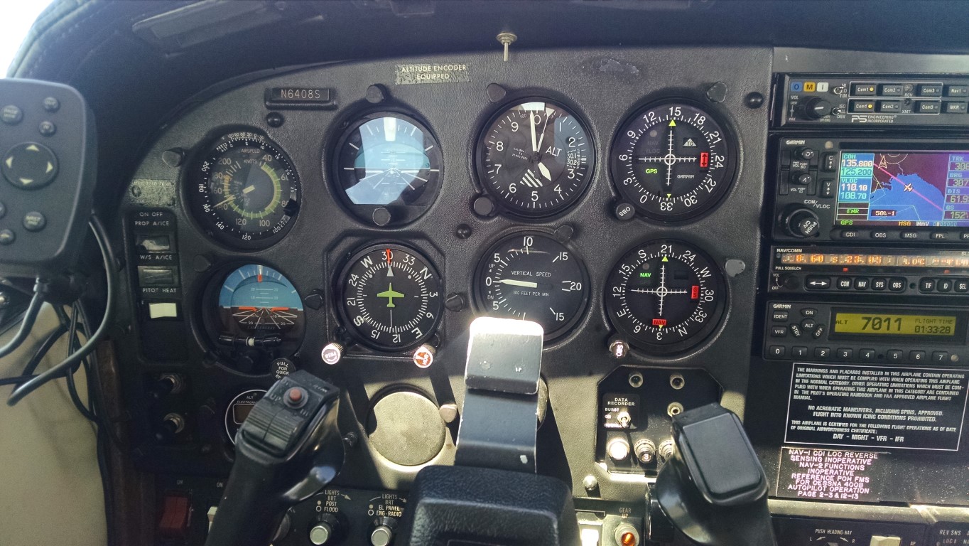
Here’s the panel I’ve been flying behind for the past 16 years.

6408S Panel 2 (low-res)

If you’re not a pilot, it may seem daunting, for me it’s been home for the last 16 years. Airspeed? Top left.  I haven’t really looked at anything other than the needle position for a long time. When I’m on base leg, the needle is about 3 o’clock. Over the runway for landing, 2 o’clock.  Vertical speed? directly over the yoke. Hard to miss being level or in a 500fpm climb. Altitude? Directly above the VSI.  It’s second nature.

Now…

IMG_20150923_092939328

So now when I need to know how fast, there’s no needle. Just to the left of center is a vertical tape with (in this case) 165 in the middle. That how fast I’m going (indicated, not actual). Altitude? To the right of center. I’m at 6,510 feet.  Vertical speed?  On the left side of the altitude tape are some hash marks that angle up and down. If I was climbing at 1,000fpm, the area from the middle to the “1” would be shaded.  For a non-pilot that hasn’t been looking at the old six-pack or steam gauges, this probably makes perfect sense.  But I’ve been flying behind those old gauges for so long that this will take some getting used to.

Gear doors, rudders and roll trim

This entry is part 4 of 7 in the series 16 - Flight Testing

After the first flight, the first order of business was to get the flutter which was suspected of coming from the gear doors. Since I was having to head up to Illinois and pack up the remaining furniture, I had Malcolm handle those tasks.

When the plane was jacked up and the gear retracted, the nose gear doors weren’t fully closed so Malcolm adjusted those.  The left main gear door was hanging down about a 1/4″ so that was adjusted as well. He checked the incidence of the wings to try and determine if that was the cause of the left roll tendency. Both wings were perfectly set. Although the right wing did have some wash-out.  But if that was a factor, it would have had the opposite effect.  So the roll issue was deferred (for now).

John went up for the second flight on 7/14.  The flutter from the gear doors was gone.  But now there’s a flutter from the right rudder.  The plan was to shim out the rudders and see what that did.  The roll tendency toward the left is still there.  John and Scott Swing both feel that shimming a wing was overkill and that if I had roll trim it could easily be dialed out.

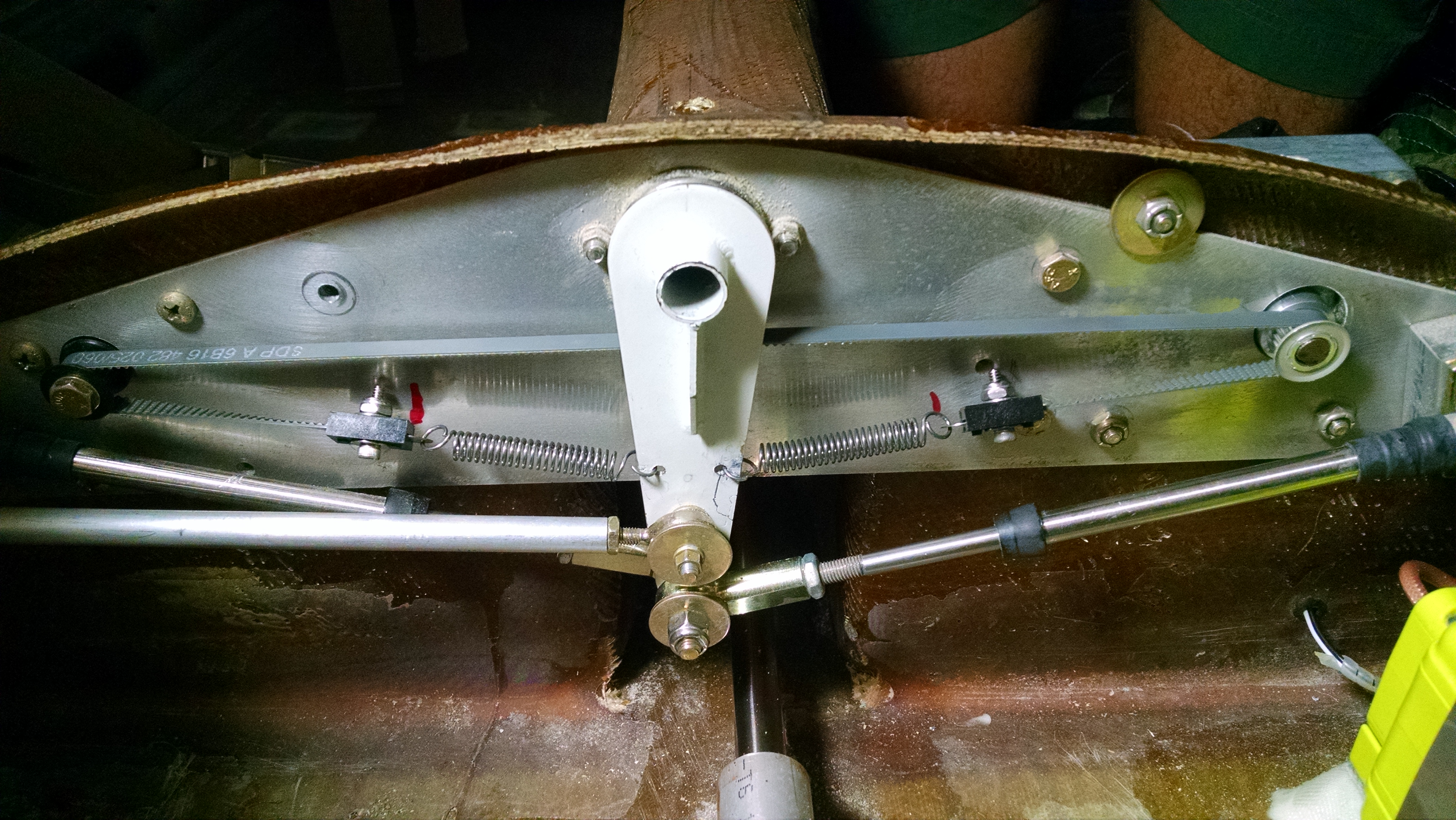
So before going any further, let’s discuss my decision to skip the roll trim mechanism. First, I wasn’t keen on the factory supplied mechanism.  Basically, it was a DC motor with a string wrapped around it a few times. One end of the string attached to a spring and then to the aileron bellcrank while the other end went around an idler pulley and attached to a spring and then to the other side of the aileron bellcrank. Here’s a picture where the string/spring attaches to the bellcrank.  Since the motor has continuous rotation, if it turns too far, the string will begin to slip.  That slippage also allows the pilot to overcome the position should the motor or motor control fail.

Click here for a picture of a dash-5 roll trim on Jorge A. Bujanda’s build site.

Well this string idea didn’t sit well for me. Geoff Gerhardt came up with a great idea of using a cog belt. So I ordered a drive pulley for the existing motor, an idler pulley and a length of cog belt. Started making the parts and pretty soon I had a good working roll trim mechanism. As I was about to get everything wired up, I started thinking…

I’ve never flown (nor heard of) a single engine piston airplane that had roll trim. I asked around and every A&P and IA that I spoke with said the same thing. Which was, if you’re using roll trim in a light single, you’re fixing a symptom while you should be fixing the problem of why it’s not flying straight.  This is what’s known as “rigging” an airplane. I had this done on the Cessna years ago. It involves adjusting the control linkages, setting the incidence of the wings and then flying it. If it doesn’t fly straight, you adjust linkages and wing incidence to get it flying straight.  So I decided that this roll trim thing is just a shortcut to properly rigging the plane in the first place.

And with that, I took all the roll trim parts off and put them in a box. No plane that I built was going to have roll trim so that I don’t have to get it properly rigged!

Then I got taken to school by Ken Baker.  I hadn’t considered dihedral.  All those other single engine airplanes have dihedral built into the wings. Dihedral is where the wings are angled up when looking at the plane from the front (or back).  With dihedral, when the plane is level, both wings a producing the same amount of lift. But if the plane rolls to one side, then the lower wing generates more lift and the higher wing generates less which causes the plane to level out… all by itself.  So if one side of the plane is just a little heavier (maybe because there’s more weight on side), this dihedral will help the plane fly level.

image3no

Guess what Velocity aircraft don’t have?

Velocity-side-Gear-Up DJ

That’s right, dihedral.

Which means that when they roll just a little, instead to dihedral basically self-correcting the unwanted roll, they actually roll even more. Which is why even minute weigh imbalance or a small difference in the wing shape can create a roll to the left or right.

So the roll trim box is going to have to get opened back up. But that will have to wait until I get back down to Sebastian.

Scott did the third flight. Malcolm shimmed both rudders. At around 165, the flutter developed in the right rudder and caused the entire winglet to begin oscillating.  Very disturbing.  When they looked at the rudders, instead of the outside surface being slightly concave (or scalloped) or even flat, they were convex (rounded out). This was causing the rudders to “hunt” for a neutral. Which means flutter. That movement transmits to the winglet causing it to start moving as well. If left unchecked it could cause the winglet to depart.

Here’s a main wing oscillation on a Hawker. (Warning: NSFW for language)


So it looks like my rudders were not properly constructed.

Malcolm removed them and began making them right.

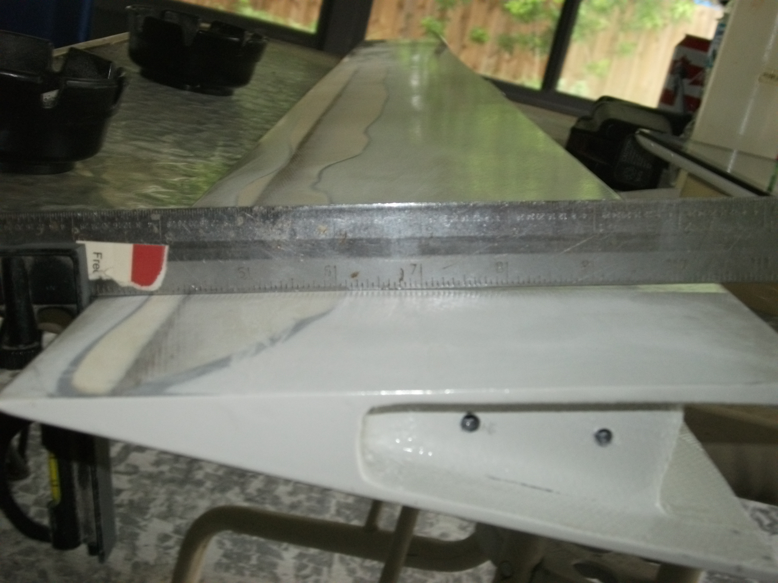
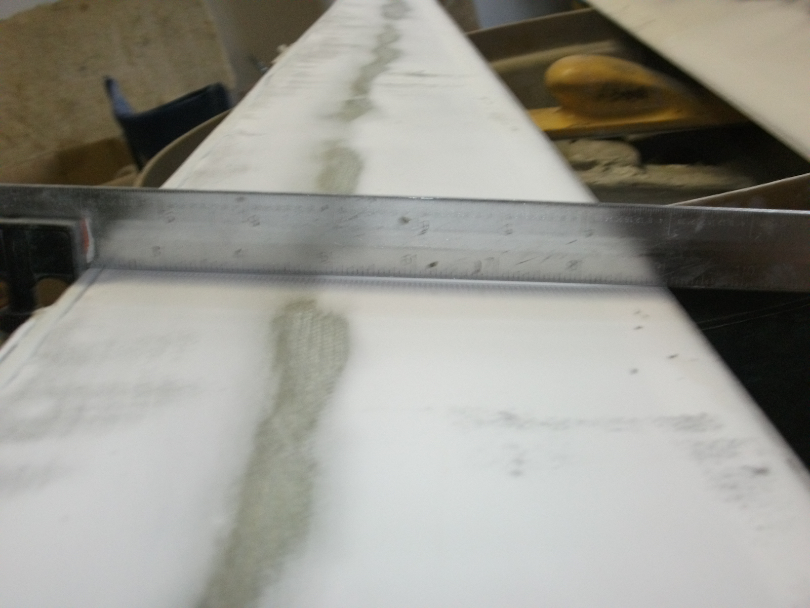
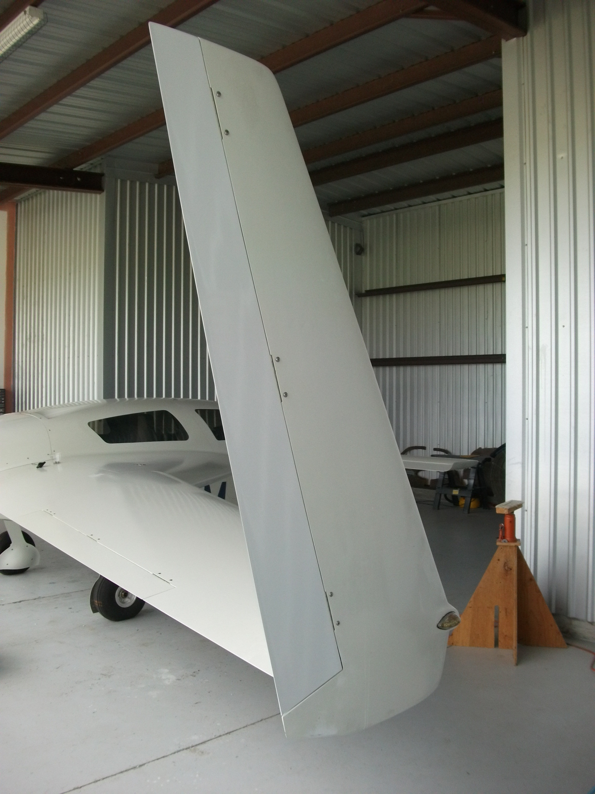
Here’s the outside surface of the right rudder. You’ll notice that it’s not concave or even flat. In fact, there’s a pretty good outward curve on that surface.

2015-07-15 Left rudder

After removing all the filler, it’s still not right.

2015-07-15 Right 1

Here’s the rudder that was causing the flutter.

2015-07-15 Right rudder

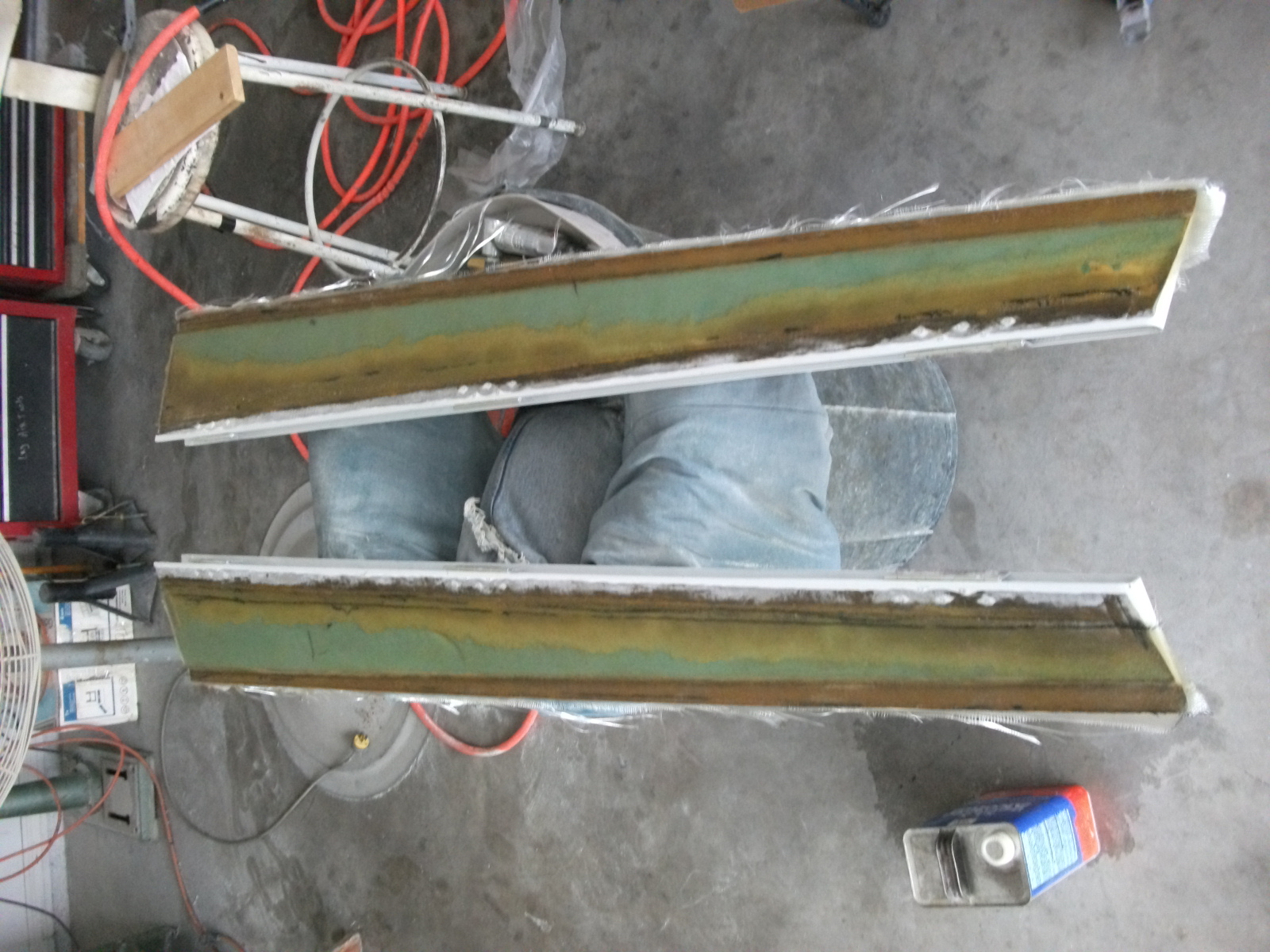
Eventually, Malcolm ended up sanding deep into the foam before the he could get the correct shape.

2015-07-16 Both

Covered with uni.

2015-07-17 003

With filler. We now have a low spot on the outside surface.

2015-07-22 009

Painted and installed.

2015-07-26 006

I didn’t want to try and install the roll trim because I wasn’t sure when Scott was going to be able to make another test flight.

On the Friday the 31st, Scott made test flight #4. The plane accelerated through 165kts with no flutter.  He said that he got it up into the “170’s”, but the data log showed a max speed of 180kts. There was some scary weather approaching so the flight was cut short.

The next day, I installed the roll trim.

Here’s my roll trim mechanism.

2015-08-01 IMG_20150801_135619526

Since I had originally intended to install roll trim, I had pulled all the wires, I just had to terminate them.  Now for the pitch trim, I went with the TCW Technologies Safety Trim controller. I did this for a couple of reasons.  The primary reason was that the Vertical Power VP-X trim driver is designed for low power RC Allen trim motors and is limited to 1amp. They don’t recommend using it to drive Velocity trim motors. The other reason I used the Safety Trim controller is that it has some really nice features:

Dual speed; it will drive the motor faster at lower airspeeds when large changes in trim are needed quickly while at high airspeeds, it drives the motor slower to prevent trim overshoot.

Runaway prevention; If the pitch trim switch should fail in the closed position, the trim motor will not continue to run.  The controller will only allow the motor to run for about 3 seconds at a time.  If you need more trim, you release the switch and then press it again.

Reversible; If the switch gets stuck, you can disable and reverse the motor with a switch on the panel.

So when I realized that I had to install the roll trim, I was thinking that I was going to have to buy and install another trim controller. But fellow builder Bob Holtaway did some testing and determined that the pitch trim pulled significantly less current that expected.  And since the roll trim has much less load than the pitch trim, I decided to go that route instead.

Everytime I work with the VP-X, I’m amazed. Just about every aspect of it is well thought out and easy to use. Once I connected the wires, it took about 10 seconds to configure the VP-X to drive the roll trim motor.  I had the trim motor wires reversed so it ran backwards. It took about 2 seconds to correct that in the VP-X configuration.

So at this point, the gear door flutter, rudder/winglet flutter and left roll have been resolved.  I’m hoping that I don’t discover another surprise that rears it’s head at 190kts.


16 First Flight

This entry is part 3 of 7 in the series 16 - Flight Testing

First flight was scheduled for July 7th. We drove down on the July 4th.  Ann came down on this trip (for some reason) :-). The last time she was in Sebastian was when we came down to talk to Velocity and take the demo flight in June of 2007.

I spent the 5th and 6th preparing for the flight by finishing up the various odds and ends that needed to be done. On the 6th, the plane moved for the first time under it’s own power.

I was very pleased with the handling compared to the trainer that I flew a couple weeks earlier. After taxiing around for a while, I picked up Ann and we did a relatively high-speed taxi (~ 50kts). Once again, the airplane tracked very nicely.  Then we went over to the compass rose to align the AHRS and magnetometers. Then we put it away for the night.

John Abraham came over around 11am on the 7th and began his preflight.  While he was doing that I explained the systems that I thought were unique to my plane.  The only thing he found was the main gear cables were a little tight. He wanted a bit more slack in them. So we loosened them.  He checked a couple other things and then said “Looks like it should fly… Let’s go see.” 🙂

So we pushed it outside.


John started the engine and we talked for a minute while the engine warmed up. Then he taxied off to runway 06.


Ann had a GoPro running and her iPhone at the same time (not sure how she did that).  The GoPro video is going to require some post-production work as the plane is so small that you can even see it. But until then, here’s the iPhone video.

John was up about 20 minutes.  During that time he check the control response, slow speed handling, monitored the engine and attempted to check the high-speed handling.

After landing, returning to the hanger and shutting down he explained that a flutter developed at about 160kts which limited the speed on this flight. He said that it seemed to be coming from one of the landing gear doors. The only other issue was a slight left roll tendency.

And with that, the first flight was over.

Now, in addition to being an “airplane” on FAA paper, it is also one in reality.

This calls for a celebration!

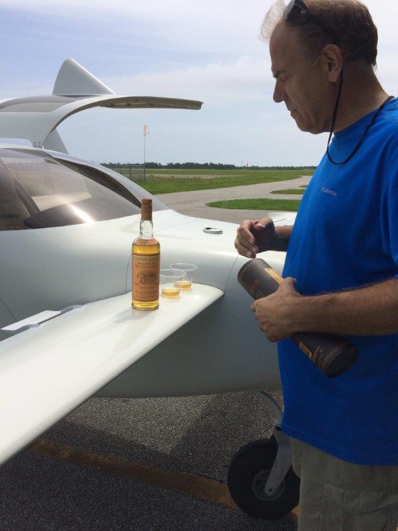
I’ve been holding my last bottle of Glenmorangie in reserve.  I had to do this because the sixteen men of Tain decided to sell their distillery to the French (YGBSM!) a few years ago. The current product, by the way, is barely acceptable for cleaning toilets. But we’ll leave that discussion for another time.

So I brought along my last bottle on this trip. I pulled out a couple of mixing cups because it seems appropriate that the cups which were used to mix the epoxy for this airplane be the preferred container for the celebratory drink.

2015-07-07

Now that’s how you finish an airplane.

13.4 Pitot/Static Remediation

This entry is part 59 of 67 in the series 13 - Electrical / Instruments

Prior to having the airworthiness inspection done, I was planning on getting the pitot/static/transponder check done. Friend and fellow builder Bob (who’s V-twin had a first flight 2 days after mine!) suggested checking the system for leaks prior to the check.

When I checked, it leaked like a sieve.  Couldn’t hold the altitude and airspeed for less than a second.  I pulled the panel (no small feat) and tightened all the fittings and still leaked. I isolated parts of the system and still had leaks. Spent a whole day trying to fix this and had to cancel the test, reassemble everything for the inspection, and come up with a plan B (actually, Plan A since the current system is a Plan B).

This brings us to our lesson for the day.  When learning to fly, you’re told that when a loss of power occurs, that you select a suitable landing spot (within gliding range) and stick with it!  Too often, as people descend, they see another spot that looks much better.  But when they try to make that spot, they run out of altitude. Now obviously, there are exceptions. But the idea of “Make a plan and stick to it” has merit.

This also applies to building. With the pitot/static plumbing, I researched all the different choices for tubing and fittings. What I decided on was “quick connect” system sold by SteinAir. I came across these when I was looking for a alternate static valve that had a toggle switch control.  The parts weren’t the cheapest (at least I thought), but it looked like a good choice.

Then someone told me that you can get “the exact” same type of fittings from Home Depot.  Early on, I made the decision not to use non-aviation parts unless I was absolutely certain that it either didn’t impact safety or that I could determine that the part was as good or better than the traditional aviation grade part. I could not make that determination with the Home Depot grade parts so that idea was dismissed.

Then I heard “Why are you going to use those fancy, expensive parts? Cessna, Piper, Beech have been using plain old NyloSeal parts for years and they work just fine.”  Well, I didn’t have a good answer for that. So I ordered a bunch of NyloSeal fittings and tubing from Aircraft Spruce. I mean, if it’s been working for everyone else, right?

Before ordering, I drew up a diagram:

Pitot-Static Diagram

Once all the parts were in, I hooked everything up and secured the fittings and tubing where necessary.

Here’s a picture after I installed the tubing and put the panel in place.  The arrows are pointing a various tubes and fittings.

2015-07-06 IMG_20140528_084725635

Not the prettiest installation, but it’s behind the panel and with all those fittings, there’s only so much you can do.

Once I discovered that the system was leaking and I couldn’t get it to not leak, I decided to go back to my original plan.

So I made up a new diagram. In the process, I decided to eliminate the “test points” in the system. I had asked the shop that’s been doing the pitot/static checks on the Cessna about what they like to see in a pitot/static system and he told me “test points so I don’t have to tap into a line.”  But it occurred to me that a single test point adds three connections to the system.  After I redesigned the system, for the new hardware, between eliminating the test points and having a 5-port manifolds, I reduced the number of connections from 44 to 28.

Old Pitot-StaticNew Pitot-Static

I also used the “banjo” elbows for attaching to the static ports on the sides of the fuselage. These fittings are very low profile which means that the interior trim will fit closer to the fuselage. Here’s a picture of a standard elbow (left) and the “banjo” elbow (right).  Oh yeah, another huge benefit is that both elbows are full 360 degree swivel.  Which means you don’t have to worry about “clocking” the fittings to get them pointed in the right direction.

2015-06-25 _20150625_143049(1)

The end result is a much neater installation that had no leaks. I also used red tubing for the pitot side and clear tubing for the static side to make it easier to identify the two different lines.

2015-07-06 IMG_20150706_081241770_HDR 2015-07-06 IMG_20150706_081249678_HDR

This is what I removed.

2015-07-07 IMG_20150707_120757151

14.99 Airworthiness Inspection

This entry is part 35 of 38 in the series 14 - Final Assembly / FInishing

Over the past 7 years, there have been many “milestones”.

Finishing all the filling and sanding and getting the plane in shiny white primer.

Hanging the engine.

2011-10-07 DSC_0071

Retracting the landing gear.

Powering up the electrical system.

2014-05-31 IMG_20140531_193001095 (Small)

Starting the engine.

2015-03-06 1633 Image0053

But those are all, what I would call, building milestones. They are events that I conside significant. There’s nothing that I’ve done which warrants the attention of the FAA.

That changed today.

This morning at 9am, the FAA DAR (Designated Airworthiness Representative), paid me a visit. First we went over the paperwork to make sure that everything was in order.

I had a momentary panic attack when he mentioned that my builders name (Donald E Johnston) and registered owner name (Johnston Donald E) were not the same. This isn’t a problem, but the data plate permanently attached to the fuselage MUST show the builders name. And I couldn’t remember what name I had engraved on the data plate. So I had to check and sure enough it was correct. Whew!

Once the paperwork was deemed correct, he began looking over the airplane. He asked to see a landing gear retraction so I jacked up the plane, retracted the gear and then lowered it. Then he looked over the electrical system. He asked who did the wiring. I said “That would be me.”  “All of it?, he asked. “Yes sir” was my response. I got a “Very nice” with an approving nod.  I get the feeling that this particular DAR doesn’t throw those comments around very often. Made me feel real good.

Then he wanted to see the electrical system powered up. Once all the screens were up, he wanted to see the nav and strobe lights function.

After that, he looked inside the nose and pointed to an oil fitting on the nose oil cooler and said: “It’s not required, but it would make this DAR happy if you were to put an indicator on that fitting so you would know if it rotates.” I pulled out a tube of torque seal and marked it as requested.

After that we sat for a while going over more paperwork. He explained that I would have a 25-hour phase I test period since I’m running a non-experimental, approved engine/prop combination. Otherwise, I would have a 40-hour phase I test period. During phase I test flights, no passengers can be carried and all flights have to be done relatively close to Sebastian. I got a pretty decent sized test area.

Phase I map

After that, she can come home with passengers.

Then I got a piece of paper seven years in the making.

_20150619_101342

10.1.3 Aerodynamic Trim (Sparrow Strainer)

This entry is part 11 of 11 in the series 10 - Control Sytem

With the airworthiness inspection in two days, I’m down to the final tasks. Not everything is required to be done for the inspection, but I would rather do things which aren’t required than not get a certificate because I missed something that was required.

The sparrow strainer is not a required item, but it’s something that needs to be done, so I’m doing it.

Using the same process as used to attach the vortilons, I marked the area where the sparrow strainer attaches. Then I masked off the area both on the elevator and mounting arms. A thin film of clear silicon adhesive is applied and then the strainer is pushed into position.

To keep it from slipping off I used a bunch of tape to hold it in position. Then I cleaned up the joint and put a nice radius on it.

2015-06-17 IMG_20150617_171334600

6.3.2 Seating modifications

This entry is part 39 of 42 in the series 06 - Fuselage

In preparation to doing the weight and balance, I need to get the seats in. The back seats I just put in the back. But I bolted down the front seats. That’s when I noticed something… With the co-pilot seat installed, it’s really difficult getting in and out of the back.  It’s doable, but not easy.

I think it’s because I mounted the seat pretty far aft on the bracket to give Ann some legroom (that girl has some long legs!).

So now the question is: How do I get that seat to move farther forward? Seemed easy to me.  Fit some seat rails that have more travel. The current ones have only about 6″ of front to rear travel.

I Googled, called, emailed every vendor I could find that makes seat rails. Zilch, nada, zip. Every single one that I found will only move about 7″ max.  I found this surprising since about every car I’ve driven for the past 20 years has seats that can move at least 12″.

At this point, I can only come up with two possible options.

1) Hit the auto salvage yards and see if I can find a low profile seat rail that will work.

2) Get a second seat rail and mount it between the seat and the bracket. That way the whole assembly can be moved forward and then the seat itself can be moved forward another 7″.

The good news is that it doesn’t have to be done right away since I’m the only one that will be in the plane for the first 25 hours and after that, there probably won’t be anyone in the back seats for a while.

Dodging weather

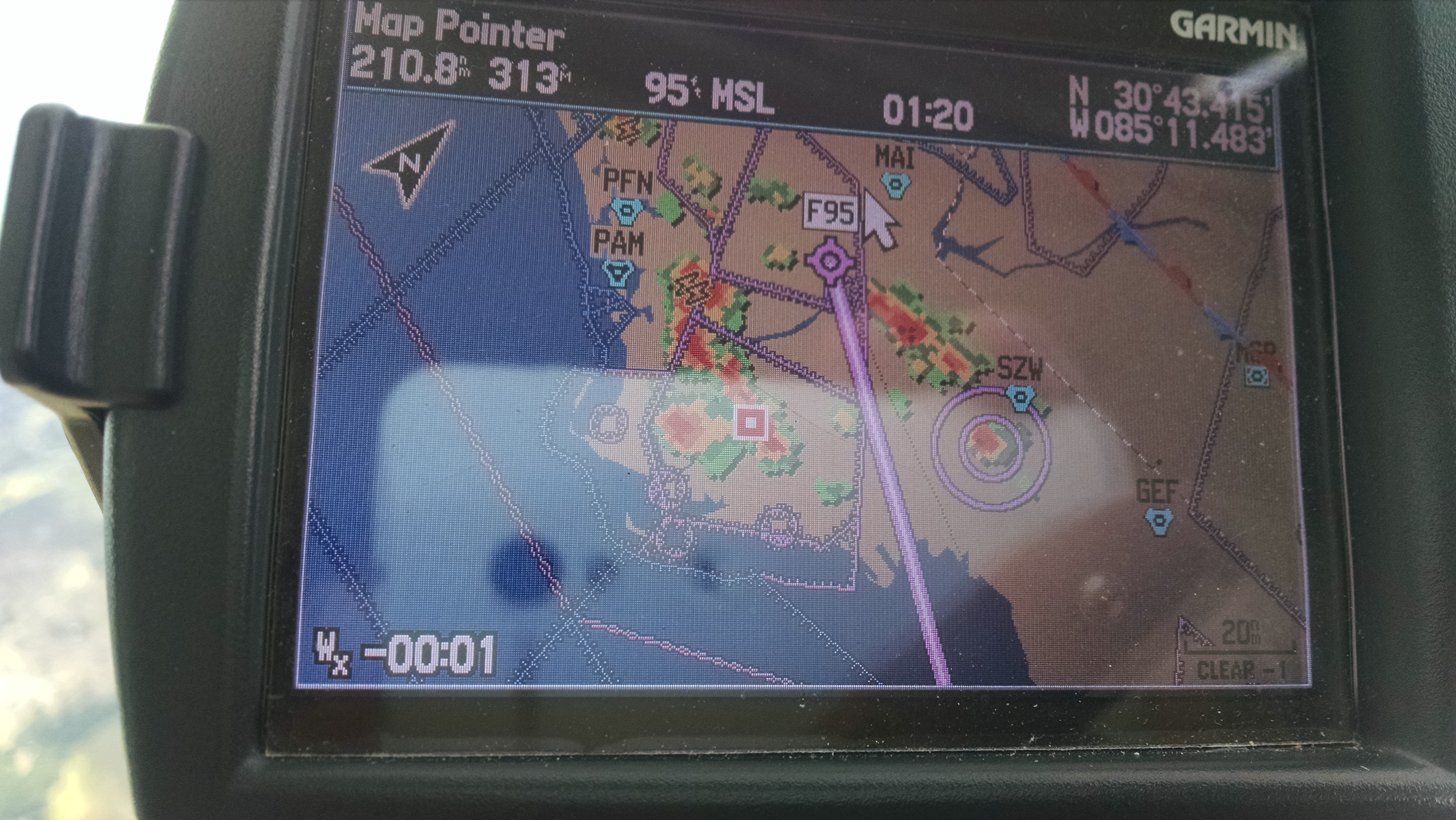
I flew down for this trip.  Instead of 7 hours each way, it’s only 2.  Of course I have to deal with weather if I fly.

Approaching the home field on the return, I had to contend with the typical afternoon thunderstorms. At first it looked like I would be able to sneak in.

2015-06-04 IMG_20150604_153654532

But then the opening between the two buildups closed and I had to loop around to the north and come in from the Northwest.

Oh well, flying in Florida.