14.99 Weight and Balance

This entry is part 34 of 38 in the series 14 - Final Assembly / FInishing

One of the final tasks before having the airplane inspected is to perform the weight and balance.

Before the airplane can be weighed there are a couple tasks that need to be performed.

First, anything that will be in the plane for flight has to be installed. No problem there. About the only thing that hasn’t been installed is the interior trim and that’s not “required for flight” and it’s not going in until after I flown off the required test flight hours anyway. But the spinner has never been installed so that has to be done.

2015-06-04 IMG_2053

Second, all usable fuel has to be removed. Arrgh!  Back over to the factory building to borrow a bunch of 5 gallon fuel cans and then siphon out the fuel.

Finally, rather precise measurements need to taken. On the Velocity, the datum point is the nose. This is a reference point that is used to identify where the weight is located. (on many single engine production aircraft, the datum point is the firewall). So I used a plumb-bob to mark the floor where the nose is. Then the distance to the center of the nose wheel axle and main gear axles is located. This is used to determine the balance part of the weight & balance which is then used to determine the CG (Center of Gravity).

Now it’s weighing time. The factory has digital scales so I borrowed them (being in Sebastian has it’s advantages).

To get the plane on the scales, I had to jack up the plane. But my (homemade) jacks didn’t have enough travel to clear the jacks so I had to raise the plane. put some wood under the wheel, lower the plane, adjust the jack and repeat (fortunately, only once). The nose was easy since all I had to do was lift it up by hand.

Checking the weight

2015-06-04 IMG_2055

And the verdict is:

2015-06-04 IMG_20150604_113345026_HDR

1,919 pounds.

Now there’s still fuel left in the strake tanks and sump. But that can be subtracted to give the true empty weight.

I was surprised at the weight on the nose. I was given to understand that around 80-90 pounds was typical and I’m at 102 pounds. If I had to guess, I would say the 24v battery and ground power receptacle are adding at least 6 pounds to the nose weight. And at least I’m not going to have to worry about hauling around bags of shot to keep the nose down when I’m not in it.

I took the weight and wheel dimensions over to the builder’s center where Rick used a spreadsheet to back out the usable fuel and calculate the CG (Center of Gravity).

N621CM W&B

12.99 Engine Woes

This entry is part 44 of 50 in the series 12 - Engine / Propeller

Since starting the engine for the first time, I’ve run into a bit of a problem.

It runs okay at higher idle speeds but it doesn’t want to run at speeds that the book says it should run at. When I first ran the engine, I couldn’t get it to run under about 1,200RPM. And I had to pull the mixture to about 1/2″ short of cutoff.

So I borrowed the fuel pressure gauges from the factory hooked them up.

2015-05-20 IMG_20150520_130951606

The engine manual says that at 600RPM the fuel pressure should be 8-10 PSI with the mixture full rich.  At 1,200RPM, I was seeing half that… and I had to have the mixture pulled out just to get that.

I increased the fuel pressure by a half turn and leaned the idle mixture by a half turn then ran the engine and checked the pressure. The pressure went up, the mixture didn’t have to be leaned as much and the engine could run at a little bit lower RPM.  Finally after FOUR turns on the pressure and and four turns on the idle mixture, I can run the engine at about 800RPM with the mixture full rich and a fuel pressure of about 11psi. If I go any further, the engine doesn’t run as well.

Since I was close, I decided to try a full power run.  The book shows full power being 2,700RPM.  But stationary on the ground I should only hit about 2,650RPM.  But when the throttle was pushed in all the way, 2,100RPM was as good as it got.

Clearly something is amiss.

I talked with Continental when I was at Sun-n-Fun and they suggested having a mechanic that’s familiar with Continental fuel systems look at it. But there isn’t one in Sebastian. The nearest one is in Sebring and he can’t make the two-hour drive over until the end of May.

I was talking with my A&P of many years and he said “Don’t pay anyone to look at the engine until you’ve had the fuel pump sent out and checked.”  And he was pretty adamant about it. I started looking for shops that do this work and the first one I hit basically said that since the engine has been sitting for four years the seals in the pump and manifold can dry out and get cracks which can cause some very strange behavior.

I pulled the fuel pump and fuel manifold (spider valve) and shipped them to Aircraft Accessories of Oklahoma.  Ken called me the day the parts arrived and said the fuel pump was “perfect”.  The only thing wrong was that the pressure was dialed up too high. I asked him if it was about four turns too high. He paused and said “uh… yeah. How did you know?” :-)) The manifold has a rubber diaphragm and it was “a little stiff” so it was replaced.

He said that I probably will never get a smooth idle at low RPMs because of the lightweight prop.  He also said the only other thing that could be wrong is the throttle body (fuel metering unit) and that if it didn’t run properly after reinstalling the parts that I should call him.

When the part arrived, I installed them and hoping for the best, fired up the engine… with the exact same results (low unmetered pressure, inability to idle at lower speeds and running very rich). I talked to a bunch of people and the consensus was that the metering unit was allowing too much fuel into the cylinders (making them run rich) which did not allow the pressure to build up (low pressure). So contrary to the official Continental Service Information Directive, I began adjusting the idle mixture by leaning it a half turn and running the engine.  The engine ran leaner, the pressure was higher and it was able to run at a slightly lower RPM.  Seems like the right track.

EIGHT TURNS later, the engine is idling at about 800RPM (a bit rough) with the mixture full rich and about 10.5psi unmetered pressure.  Well, I’ve been here before.

So then a full power run was done. The engine hit about 2,650RPM but then dropped to around 2,575.  Because the RPM dropped after peaking, it indicated the prop governor was now limiting the RPMs.  I backed out the prop governor and did another full power run and was able to maintain 2,650RPM.

That’s great… But the fuel pressure was very low for that power setting.

Now there’s an adjustment for this (high pressure adjustment).  But that adjustment will throw off the low pressure adjustment.

At this point, I’ve been fighting this since March.  I’ve spent about 18 days working on this and pretty much nothing else. It’s time to call in experts. Another builder had similar problems and called in Leading Edge Aviation from Tampa. I put a call into them and we made plans for Jonathan to meet at the plane.

When he came in to work on the other builder’s engine, he arrived at 9am and spent the day here.  But he told me that he’d arrive around 5pm!  I asked why and he said that it wouldn’t take very long (the other builder had a twin turbo-charged version of the engine). I was still surprised… and skeptical so I made sure that I had plenty of lights available.

So the day came but he was delayed a bit and ended up landing at around 6:15. He bought his own gauges and (small) handful of tools.  So we pulled out the plane and started it up. While he did get a pressure reading at 600 RPM, it was pretty ugly. He was working the throttle to keep the engine from stalling and he RPM was bouncing around so much that he would have to yell “NOW” whenever the engine touched 600RPM so his co-worker could read the pressure. Which needed tweaking along with the idle mixture. But not much.  At least I got that right.

Once that was set, we ran the engine up to full power and then the metered pressure needed adjustment… Which required quite a bit of adjusting. But that required going bach and adjusting the unmetered pressure and idle mixture adjustment. After only about an hour, it was finished!

Bob (another builder who’s building a twin) was on hand to observe pointed out “I told you that you should have called them two months ago.” And he did… And I should have. So I bought him dinner. Next time I’ll listen to Bob.

Time to begin taxi testing.

14.1.7 – Vortilon Installation

This entry is part 33 of 38 in the series 14 - Final Assembly / FInishing

I previously marked the location and alignment for the vortilons. Following Malcolm’s advice, I marked the outline of the vortilons and then masked the wing about a 1/4″ larger than the pad.  I also masked the top of the vortilons.  This will eliminate a lot of cleanup afterwards.

Then cleaned the wing and vortilons with alcohol. Next I applied a layer of clear silicon adhesive to the vortilon and placed it in position. Then I used more masking tape to hold them in position while the adhesive cured.

2015-04-21 IMG_20150508_100858855 2015-04-21 IMG_20150508_100915453 2015-04-21 IMG_20150508_100927621

16.1.1 Data Plate

This entry is part 1 of 7 in the series 16 - Flight Testing

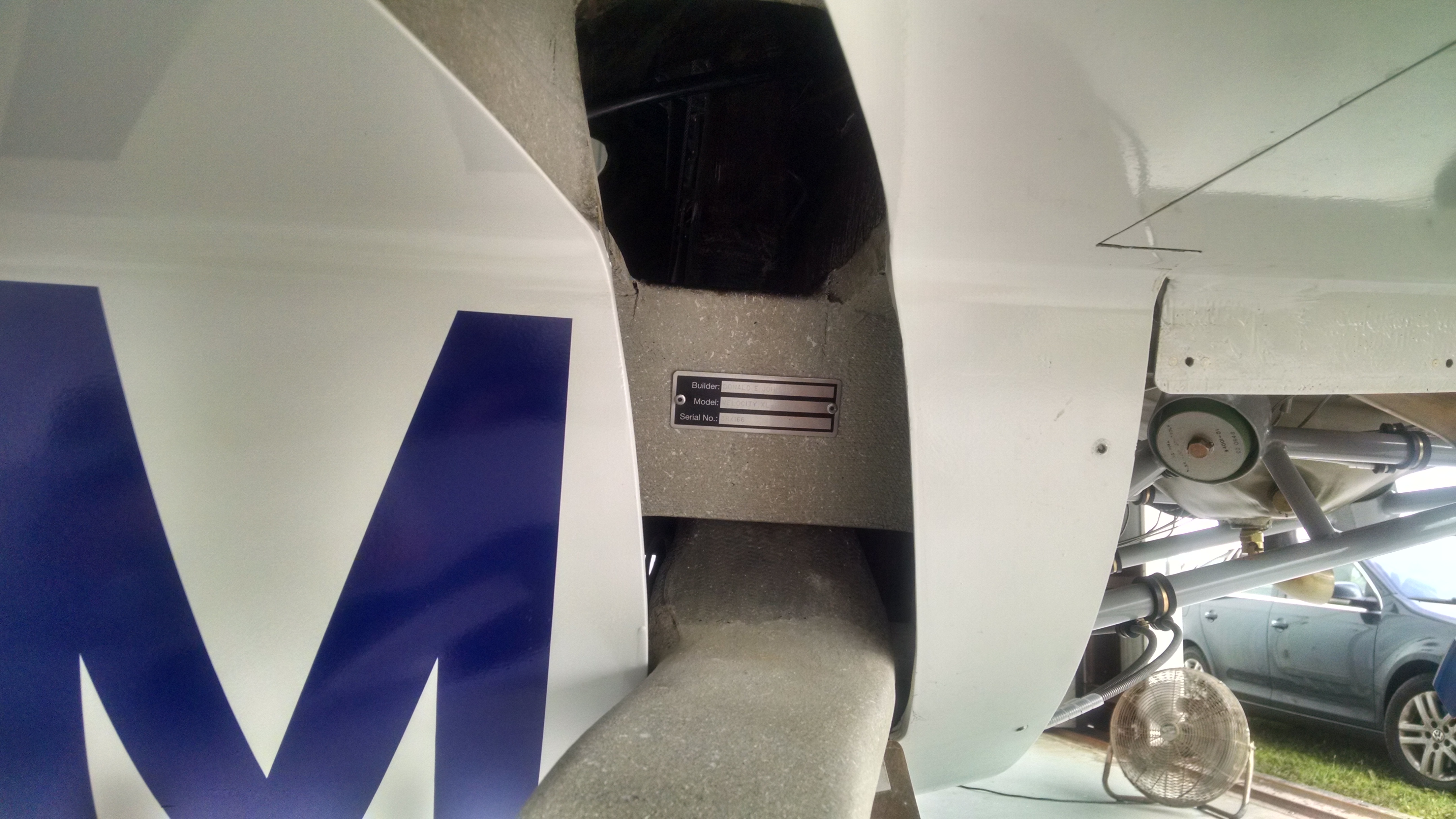
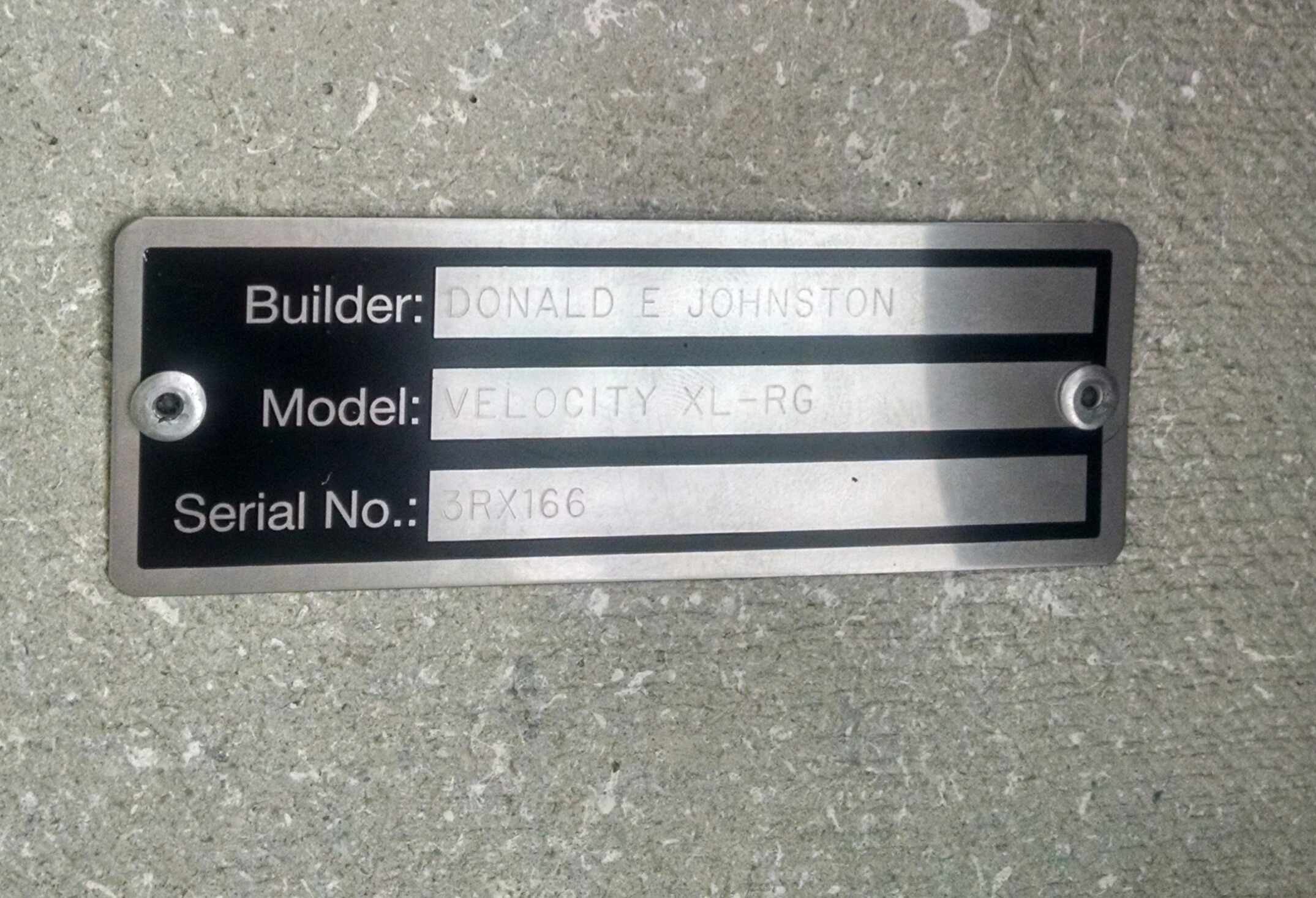
While I was having all the switch panel overlays engraved by Aircraft Engravers, I also had them make my data plate.

Some builders put it on the outside of the fuselage but I put it on the transverse bulkhead.  It will be visible on the ground but not be on the fuselage skin.

2015-04-20 IMG_20150420_085422940_HDR2015-04-20 _20150420_085438

Hot!

I don’t know if it’s a heat wave, but I had to quit working early (around 1pm) and come in at 4am to avoid the worst. With no insulation and only one door, it got very uncomfortable in the afternoon.

2015-04-20 _20150420_073557

16.1.1 N-Numbers

This entry is part 2 of 7 in the series 16 - Flight Testing

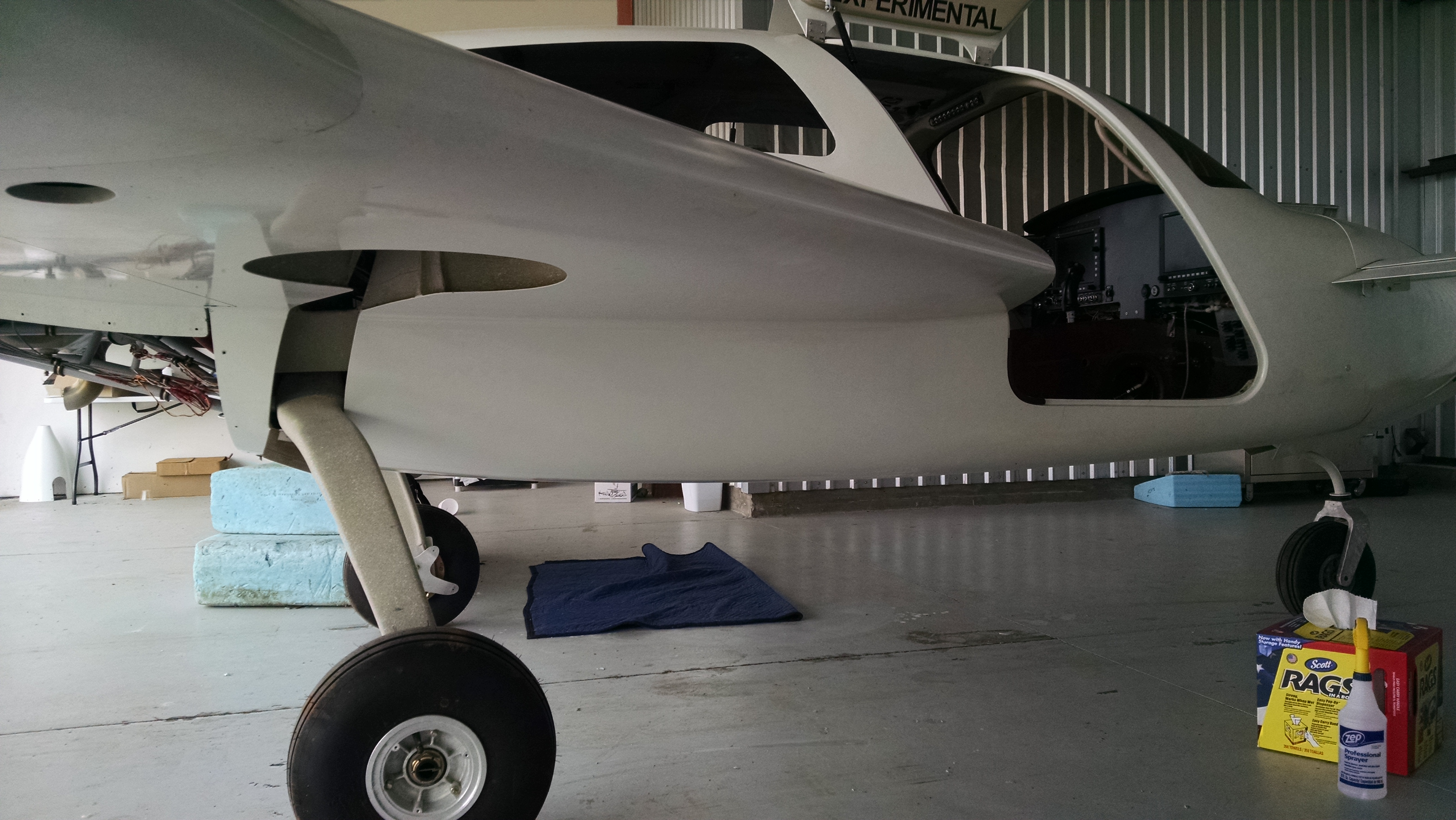
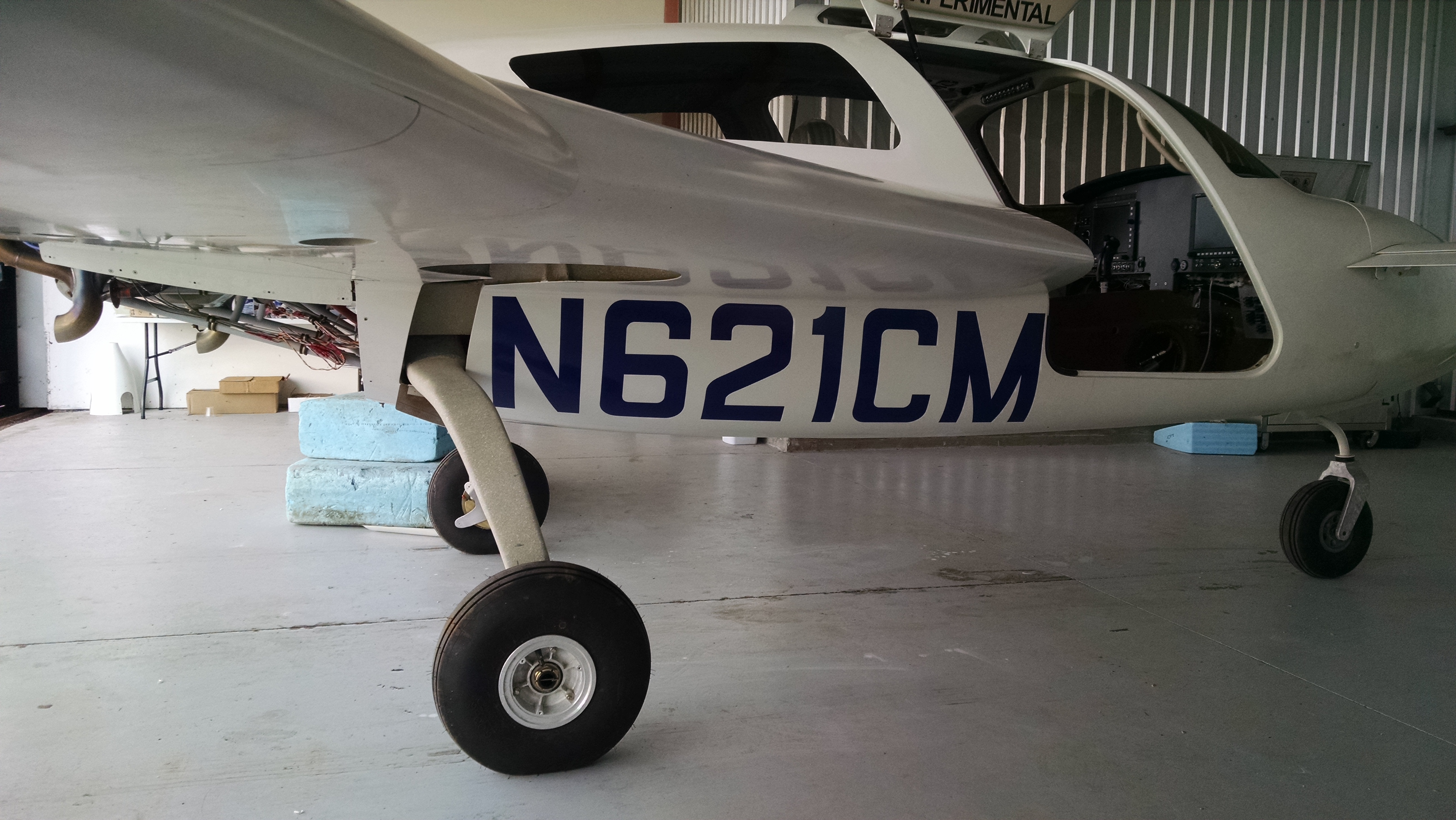
Since I will initially being flying in primer and not paint, there is no reason to go to the trouble of painting on the registration numbers. So I looked for temporary N-numbers.  I looked at a couple of suppliers and found Ace Graphics. After exchanging a couple emails with Bruce I placed the order for Royal Blue, Semi Rounded numbers.  I chose royal blue because the propeller already has trim paint that looked like royal blue. The N-Numbers arrived while I was down working on the plane.

Before starting to apply them, I hit the area under the strake with some 1500 grit sandpaper to remove any overspray from when we painted the top half.

2015-04-18 MG_20150418_162737540

Once I had a nice smooth surface, I taped the N-numbers to the top of the area under the strake and then cut between each letter/number. Then it was just a matter of peeling the backing paper away and using a spreader to apply the numbers.

2015-04-18 IMG_20150418_165534165  2015-04-18 IMG_20150418_161437875

13.99 Installing Engraved parts

This entry is part 57 of 67 in the series 13 - Electrical / Instruments

Once I received the engraved parts, it was time to install them.

The fuel caps were easy.

2015-04-16 IMG_20150416_065056544

The door handles were a bit more more. But just as satisfying.

2015-04-16 IMG_20150416_065036011

The engine controls were also easy to install.

2015-04-16 IMG_20150416_084355857

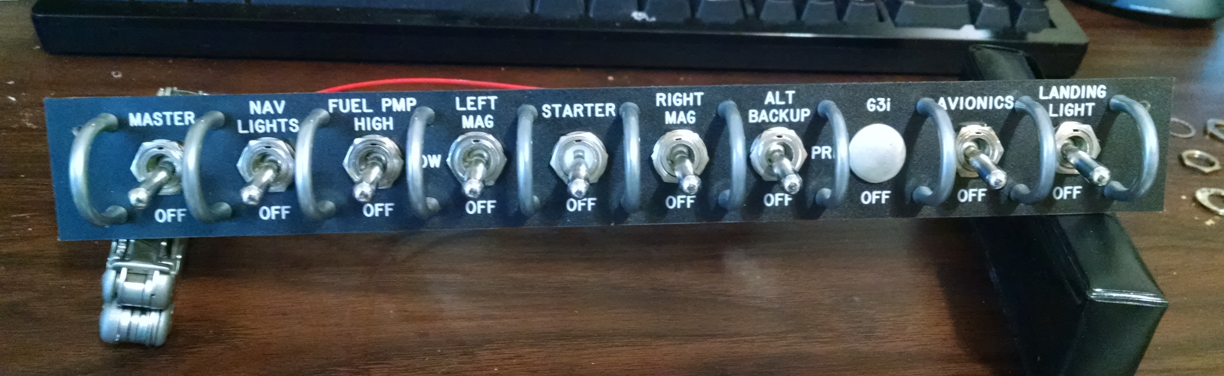
The switch panel overlays were a bit of work since they are actually under the switch hardware. But the result is exactly what I was looking for.

2015-04-16 IMG_20150416_084402820  2015-04-16 IMG_20150416_0844374892015-04-16 IMG_20150416_084415426

13.99 Instrument Panel overlays

This entry is part 56 of 67 in the series 13 - Electrical / Instruments

I received an early birthday present today.

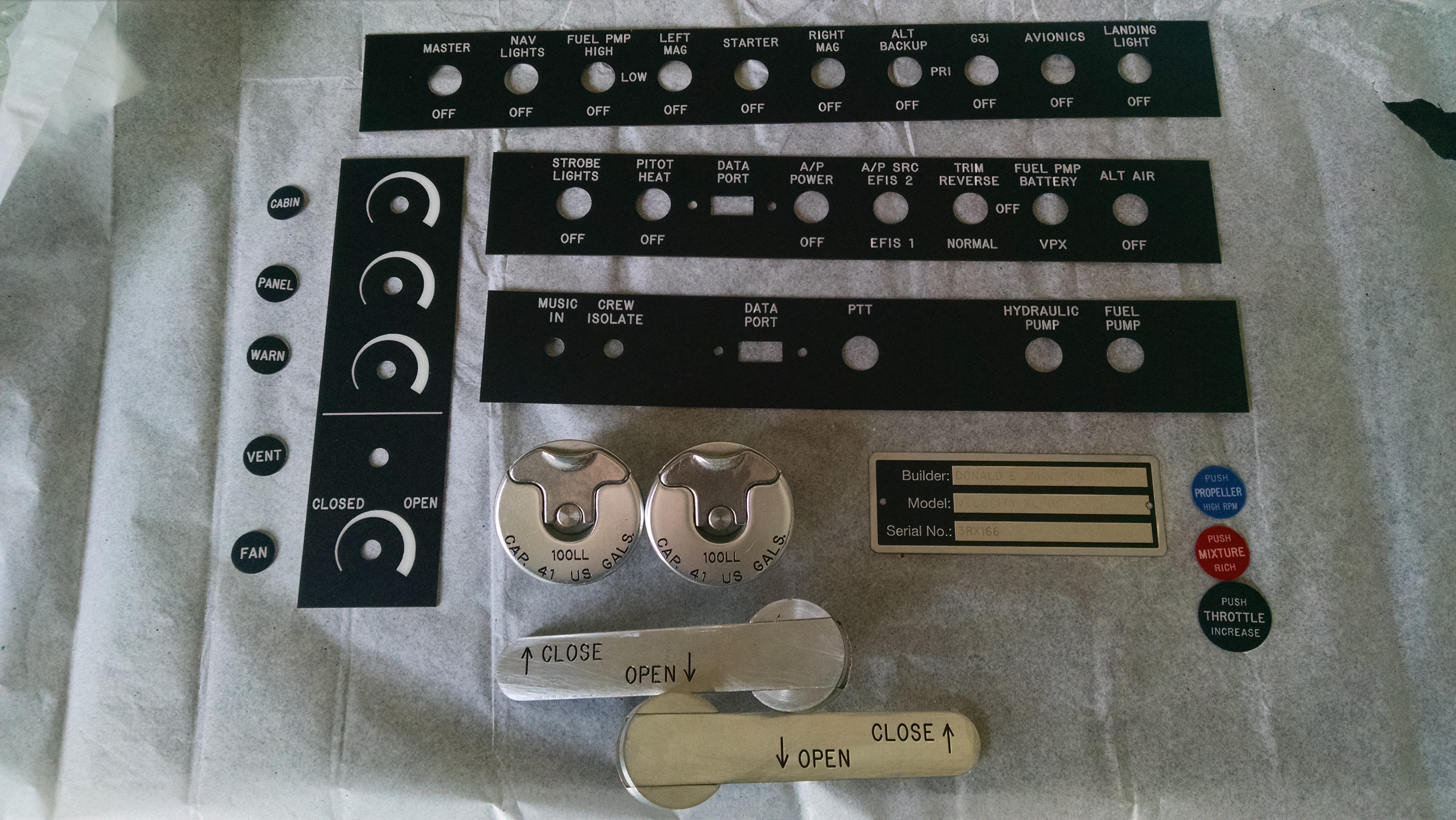
2015-04-08 IMG_20150408_105606701

I ordered this through Aircraft Engravers.

So no stickers on the around the fuel caps or on the door.

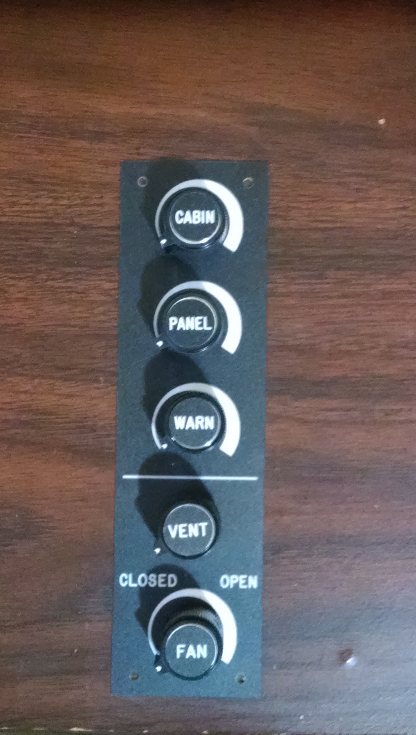
I brought the switch panels home so I could work on the drilling out the mounting and switch guard holes.

Lower Left Switch Panel before and after.

2015-04-08 IMG_20150408_130740804 2015-04-08 IMG_20150408_144929647

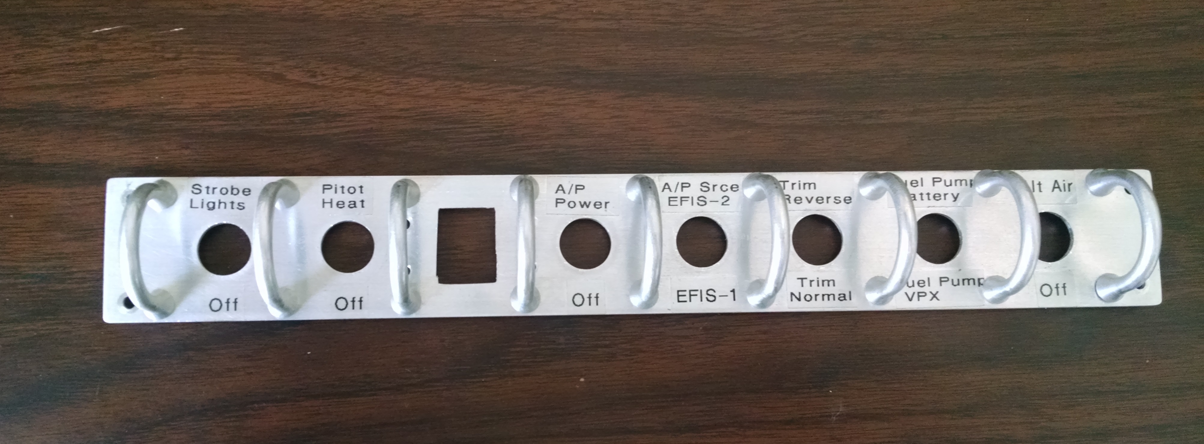
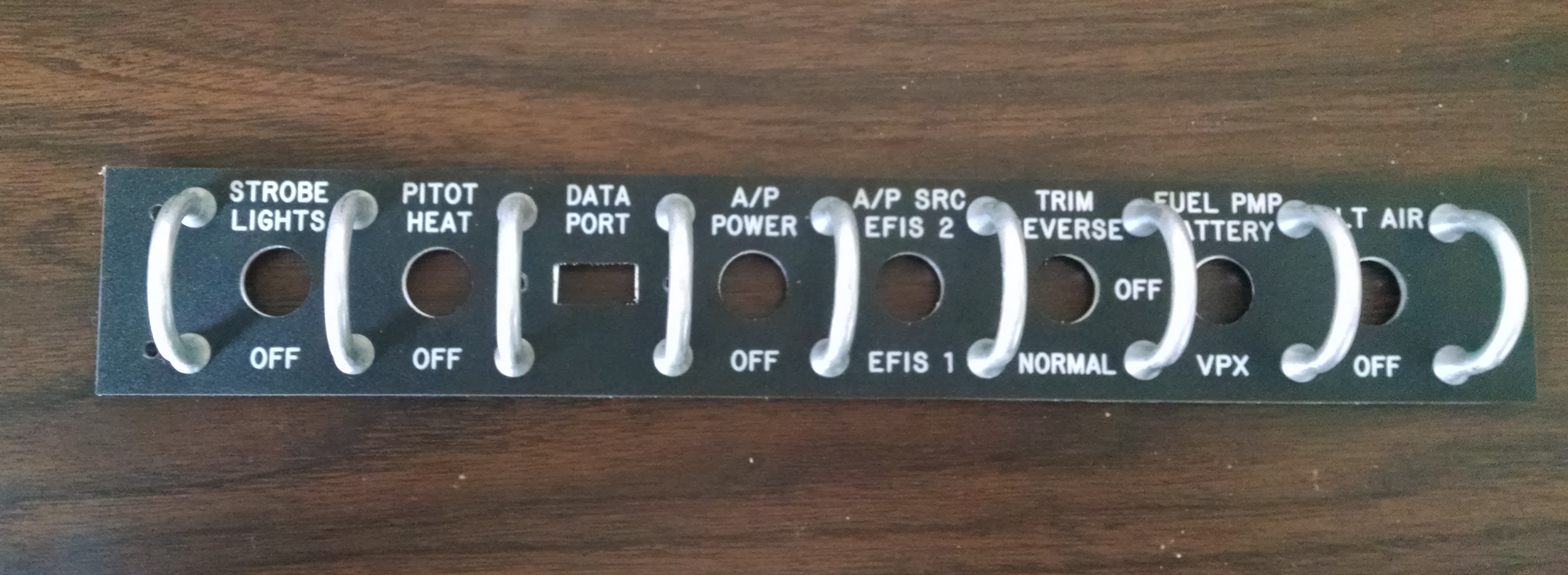
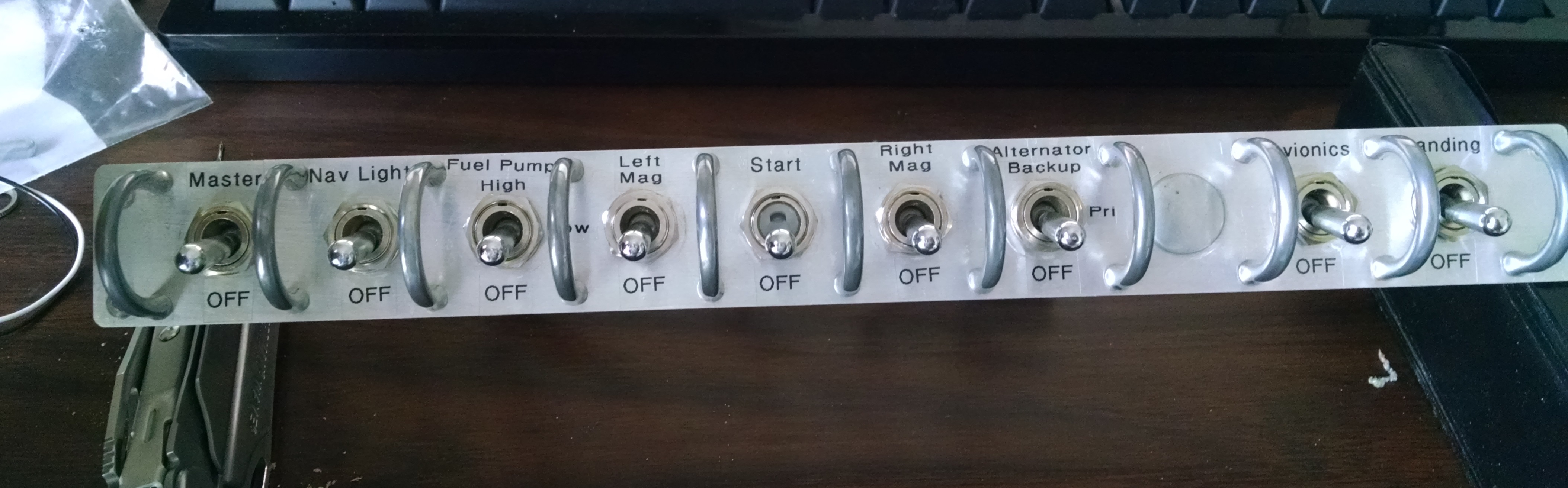
Overhead Switch Panel before and after.

2015-04-08 IMG_20150408_1531498192015-04-08 IMG_20150408_185918207

Light Dimmer and Vent Panel.

2015-04-08 IMG_20150408_190513561

5.1.4 Window Scratches

This entry is part 15 of 16 in the series 05 - Doors / Windows

Since taxi testing is hopefully going to be happening soon, I decided to remove the plastic covering the windows.

I’ve been pretty diligent about keeping the windows covered.  I make sure the window is spotless, then use a fresh sheet of plastic and tape it down tight with good duct tape.  The only time I remove the covering is when I needed to work on the window/fuselage interface.

But when I removed the plastic, I discovered some areas that I first thought was dust, but turned out to be scratches. My guess is that there was just enough loose plastic that during transport it was able to rub on the windows.

2015-04-03 IMG_20150403_084049782

I had purchased some Scratch Off a couple years ago (just in case) and was getting ready to try it out. Scott Swing dropped by one morning while I was still trying to get un-bummed about the whole window thing and I showed him the state of the windows. He was totally nonchalant about it.  He said that windows get scratched all the time. I told him that I had some Scratch Off that I was going to try and he told me how he does it (and I’m pretty sure he’s done a few). 2,000 grit sandpaper and Meguiar’s PlastX.

To say I was doubtful would be an understatement.

I already had some 2,000 grit sandpaper for knife sharpening so I went to Walmart and picked up some PlastX for about $7. But I didn’t want to test this on the actual windows.  So I went over to the factory and got a piece of scrap window material.

It didn’t have any scratches so I made my own… with 180 grit sandpaper.

2015-04-02 IMG_20150402_125826429

The marks on my window weren’t nearly that bad but I felt that if I could come close to fixing scratches that bad then my windows would be a piece of cake.

Because these were some serious scratches, I decided to start with 1,000 grit then 1,500 and finally finish with the 2,000 grit sandpaper. That definitely removed the deep scratches.  Then I used the PlastX with a paper towel (I left my good microfiber towels in the Cessna). After a minute or two polishing:

2015-04-02 IMG_20150402_131438879

I didn’t do as good a job as possible with the sandpaper and putting on the polish with a paper towel isn’t even close to the correct way, but the results indicate that this is going to work just fine.

Later I told Scott that I tested it on some self-inflicted scratches created with 180 grit sandpaper.  He said “ONE-EIGHTY!!!”  Hilarious. Hey, go big or go home.

14.99 Placards

This entry is part 32 of 38 in the series 14 - Final Assembly / FInishing

There are four exterior placards and one data plate required.  The N-Number on each side and an “Experimental” placard at the each entrance (so when anyone gets in, they know it’s a experimental aircraft).

Because the aircraft is capable of speeds in excess of 180kts, 12″ N-Numbers are required. Since these are effectively temporary, I ordered the N-Numbers from Sporty’s because they were the cheapest. When I went to apply the numbers, I discovered two things. 1) They are only 11.5″ tall and 2) the spacing is such that they won’t fit in the space available. So it looks like I’m going to have find a different supplier for the N-Numbers.

The “Experimental” placards fit fine though.

2015-04-01 IMG_20150401_091125782