11.1.5 – Premolded NACA Scoop Installation

This entry is part 2 of 17 in the series 11 - Fairings

This morning, I started on engine cooling. In a conventional airplane (with the engine in front), there are openings at the front to allow ram air into the engine compartment to cool the engine. Since aircraft engines are air cooled, this is very important. Because the Velocity has a rear mounted engine, cooling is a challenge. The early Velocities used a pair of scoops on top of the fuselage just forward of the engine compartment. The scoops were similar to the hood scoops that you used to see on some high performance cars. The problem with scoops is that they aren’t very efficient and since they protrude into the airstream, they cause drag.

So instead of air scoops, we will use NACA Ducts. NACA (National Advisory Committee for Aeronautics) was the precursor of NASA. They discovered that if you create a recessed opening with the right shape, you can get more air with no drag.

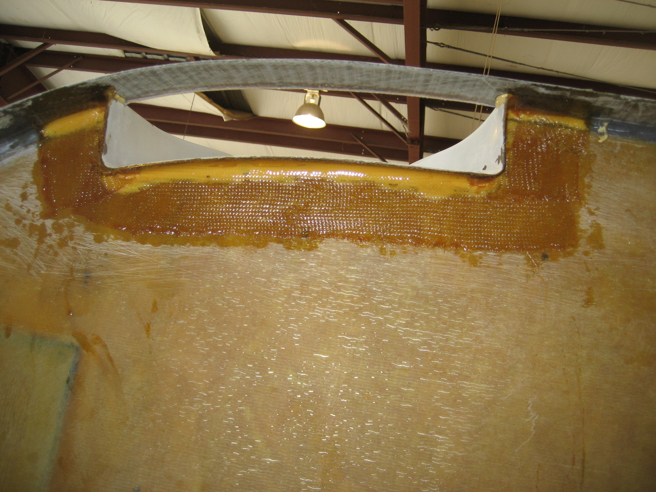
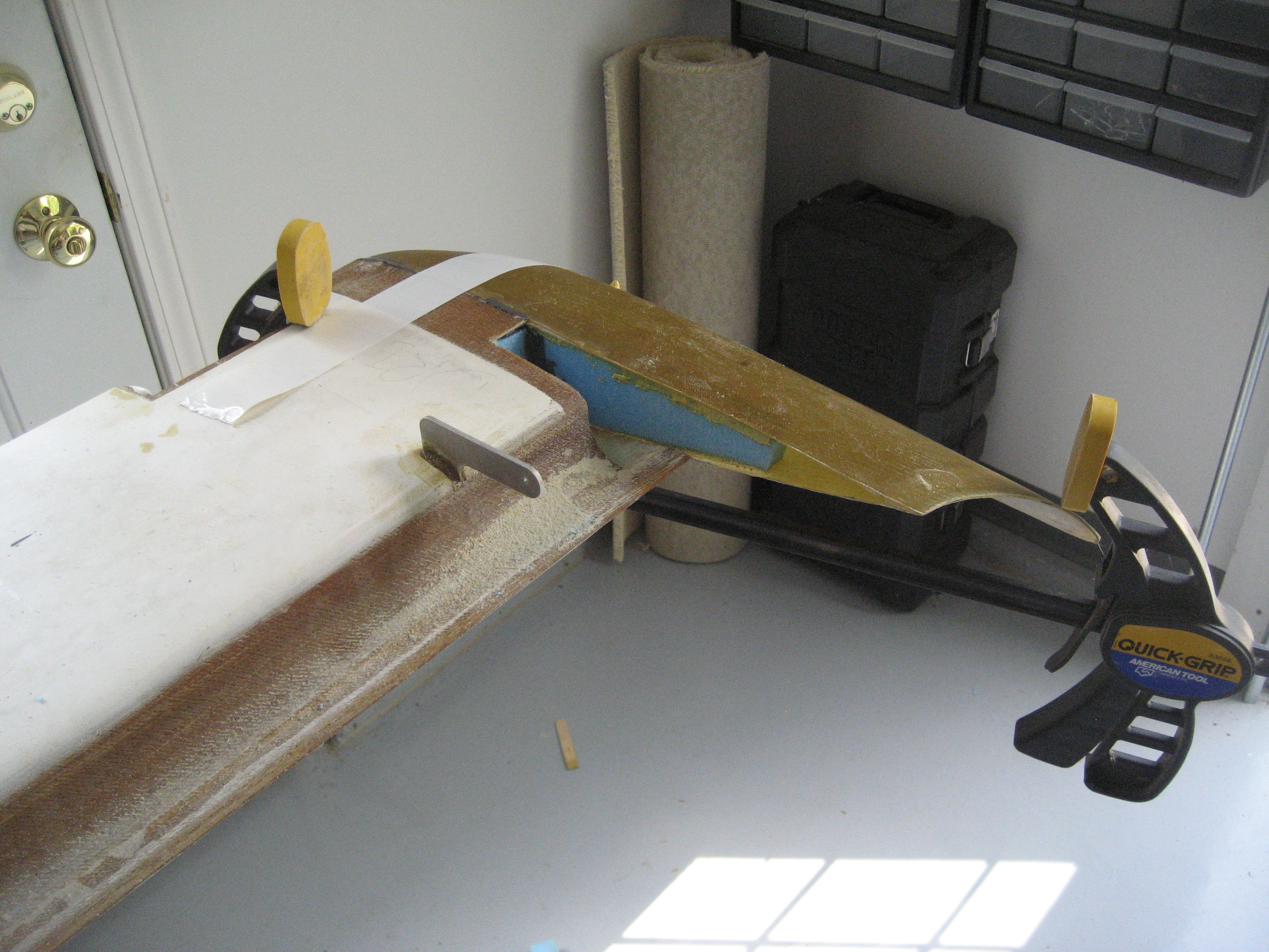
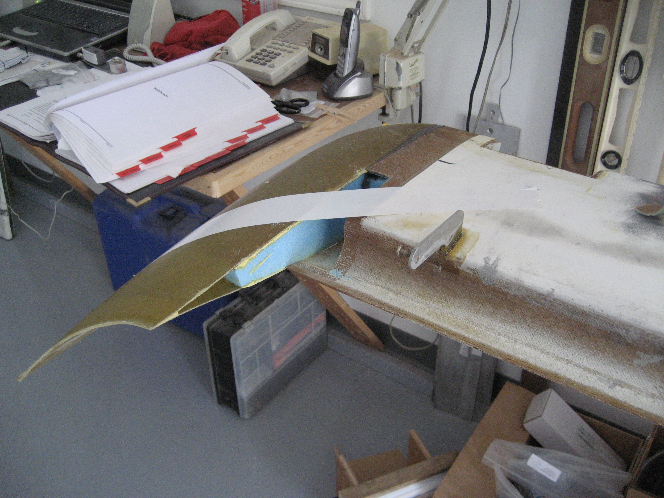
So my first task was to cut out the two openings for the NACA ducts to the engine compartment and one for fresh air to the cabin.

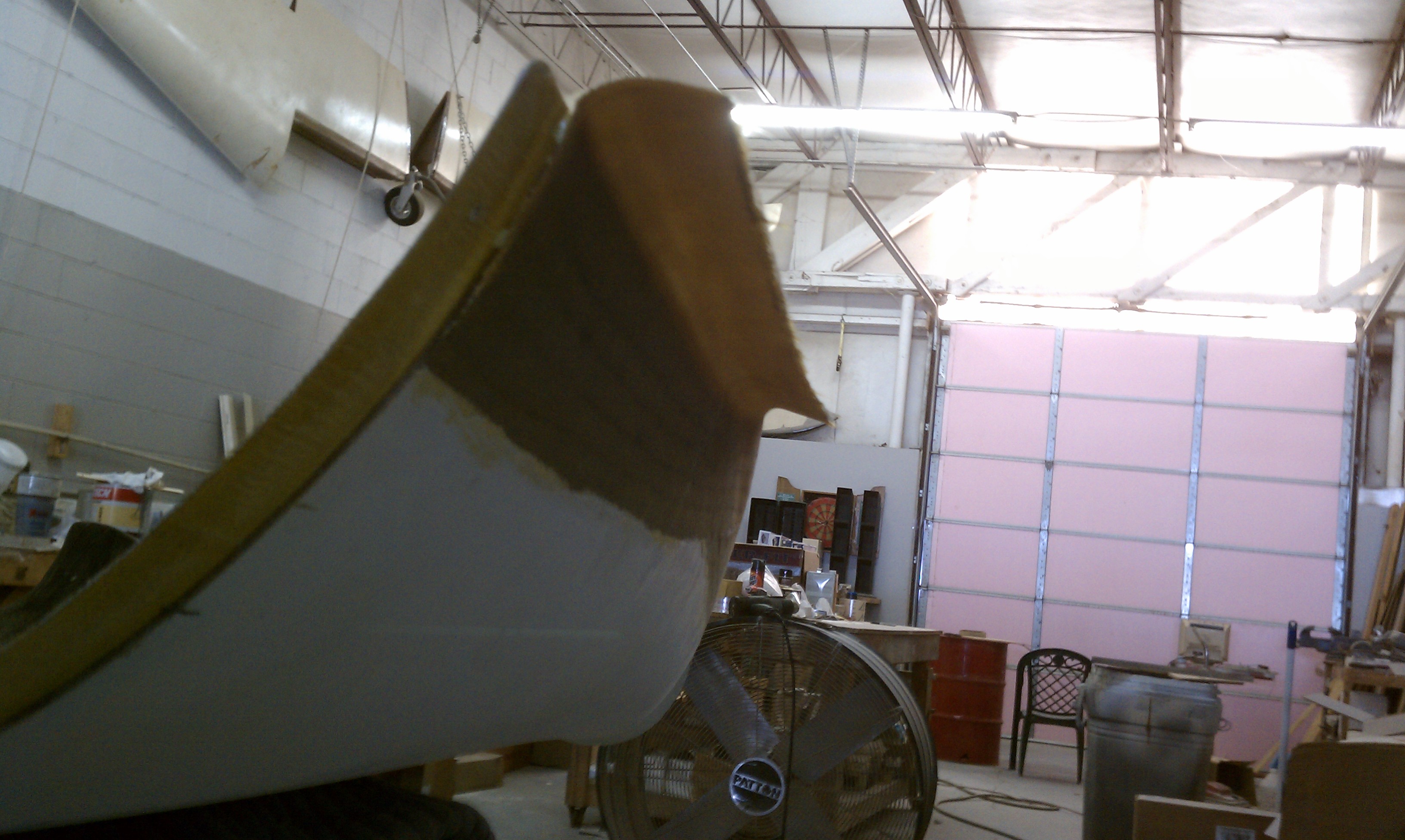
From the back looking towards the front at the top of the fuselage. You can see where the two large ducts will be. There’s also a smaller fresh air duct in the middle. The tan colored area is the rear of the fuselage (also know as the firewall) where the engine will be mounted. I’ve also marked the openings in the firewall for the ducts.

Here, I’ve cut out the engine cooling ducts on top of the fuselage. At this point, I haven’t done the fresh air duct or the firewall openings (although they are marked).

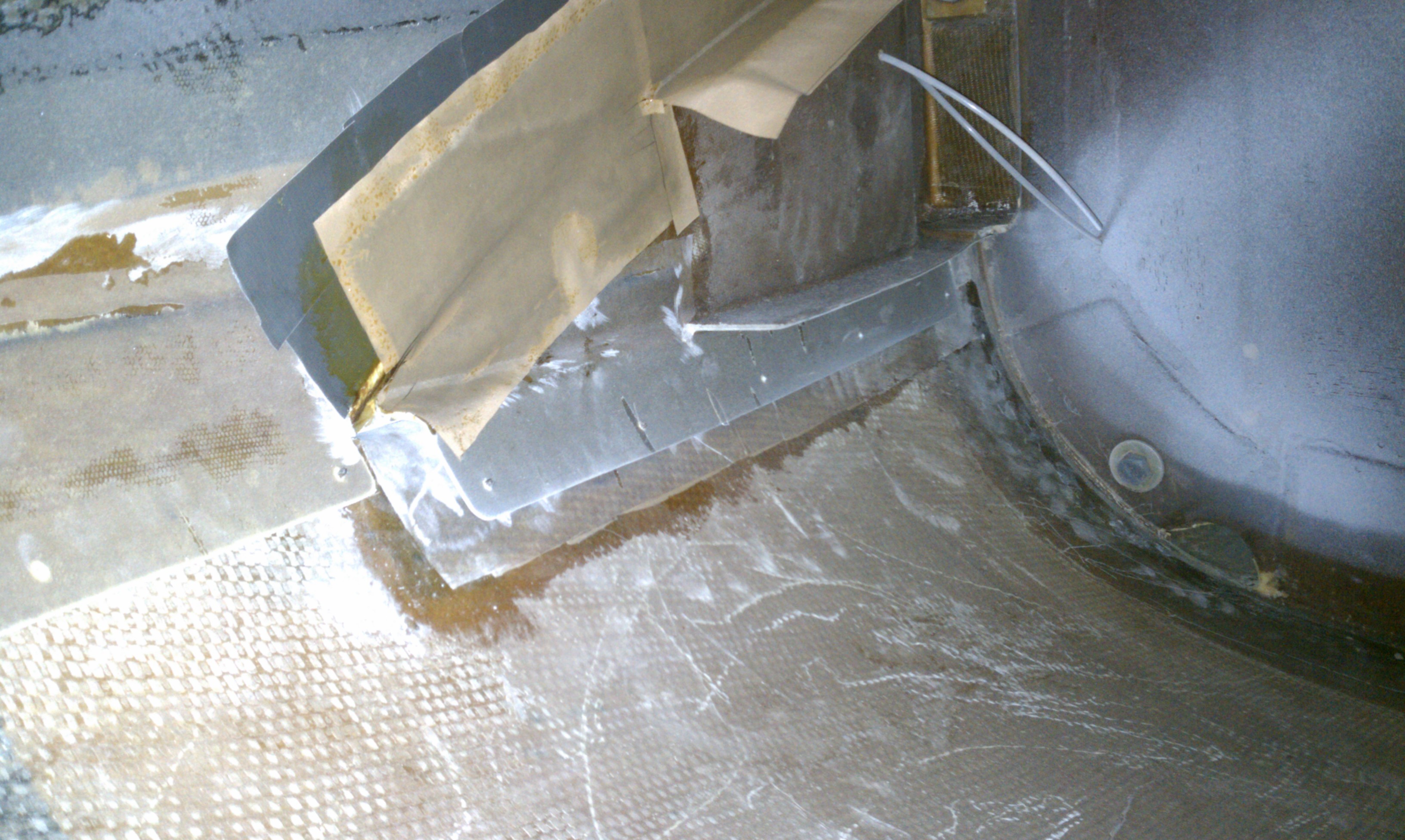
After cutting the small NACA duct and the firewall openings, I prepared the surfaces mounted all three ducts with structural epoxy.

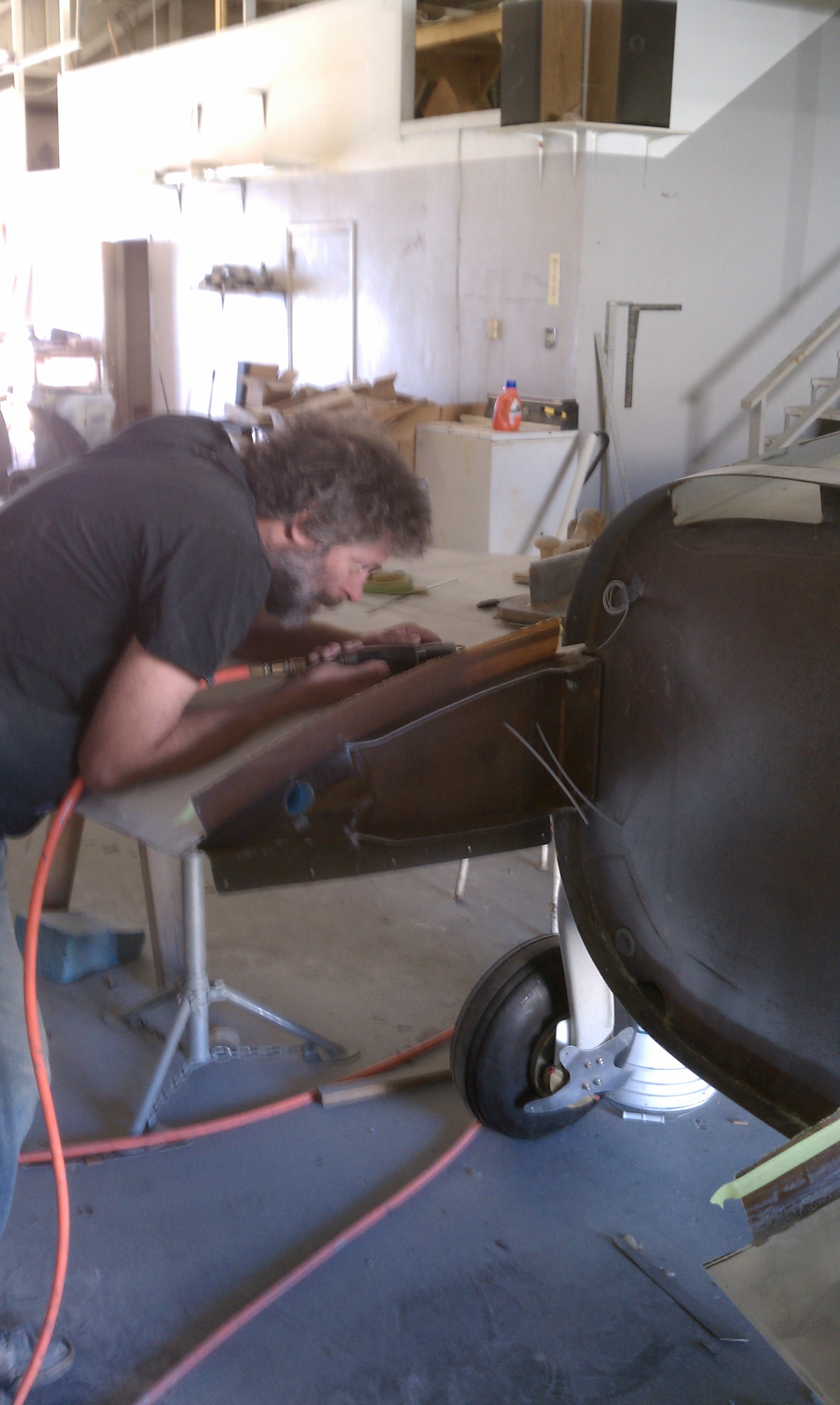
One of the things I’ve got be better at is taking pictures. When I get rolling on a task, I forget to pull the camera out and take pictures. This is why there are no pictures of the installed ducts and flight controls in the keel.

11.2.1 Canard Tip Installation

This entry is part 12 of 17 in the series 11 - Fairings

The next step would be putting on the canard tips. But before I could do that, I had to make a slight detour. The wiring for the lights will along the inside of the canard through holes that were drilled through the foam core when I was down in Florida. But at the time, I didn’t know how big the connector was. Turns out it’s just a little larger than the hole. So I had to make a new, slightly larger drill bit using a piece of 1/2″ electrical conduit. I cut a saw-tooth pattern in the end and twisted it through the existing holes and enlarged them a bit.

Canard end before.

  2008-08-08 1831 IMG_7308

The first step is to make a cutout for the elevator counterweights. These weights counteract the weight of the elevator to eliminate downforce caused by the weight of the elevators. The counterweights are recessed in a pocket that I have to create.

First I mark the location of the counterweight pocket.

  2008-08-08 1831 IMG_7309

Then cut it out.

  2008-08-08 1841 IMG_73122008-08-08 1841 IMG_7311

Then glue on the canard tip. The tricky part here is to make sure that both tips (left and right) are symmetrical. For this I used my laser level again. Once I had the canard level, I shot the laser across both tips and adjusted until they were level. This side gave me some problems so I had to “persuade” it with a clamp until the glue set.

  2008-08-09 1353 IMG_7314

This side only needed a little tape to stay in place.

  2008-08-09 1353 IMG_7316

This is were I discovered a minor glitch. When I was drilling the holes for the screw that attaches the elevator to the torque tube, it turns out that my alignment was more precise than the canard itself. As a result, the elevators are not perfectly aligned. I didn’t notice it before because there was no reference. With the canard tips on, it was obvious that one elevator was lower than the other. Not a huge problem. I just need a new aluminum bushing that I’ll redrill. So until I get that, I’ll put the remaining canard tip work aside.

11.1.3 Upper Cowl Wing Flange

This entry is part 14 of 17 in the series 11 - Fairings

Before starting on the top of the wings, the upper engine cowl to wing root flange has to be created (The bottom was done when the plane was upside down).

With the wings attached and the upper engine cowl mounted, duct tape is applied to the inside of the cowl so the layups won’t stick to the cowl. Then the layups are applied to the wingroot and extend up on the cowl.

 Here’s a picture looking at the right wingroot from inside the engine cowl. The layups are covered with peel-ply and you can see the duct tape on cowl.2010-10-29D

And for the left side
2010-10-29C

Once the layups cure, the cowling is removed and the newly created flange is trimmed.

This is Malcolm trimming the flange on the left wing.
2010-10-29E

Finished flange on the right side.

2010-10-29F

Once the cowling flange was cured and cut, we put the cowling back on and created a flange on the outside. This flange will lay on top of the wing. We were working pretty quick and I didn’t get a picture until it was cured and we had removed the cowling but the process is the same as for the lower cowling flange.

This is a picture of the flange on one side of the cowling (the cowling is upside down).
2010-11-02C

11.2.2 Counterweight Fairings

This entry is part 10 of 17 in the series 11 - Fairings

The elevators have a counterweight at the outboard end to balance them. A pocket is cut into the canard to allow the elevator through it full movement. The weight on the outboard end isn’t enough to completely balance the elevators so additional weight is added to the center pivot. But to get the elevator perfectly balanced requires a LOT of weight at that center position. There were some reports of flutter developing with this setup so the factory has recommended adding the additional weight at the outboard position. This will require making the existing pocket larger. I thought about adding the weight outboard of the existing weight but that would have been a pain as my canard tips are hollow. So I decided to add the weight inboard of the existing weights. I checked with Scott at the factory and he said that would be fine.

Here’s the left side pocket with tape marking the cut.

After the cut is made and glassed in, I’ll have to make the fairing (the “bump” above the pocket) larger. Rather than make a new foam block and cover it with BID, Malcolm said that since it’s such a small amount that it would be good to just mold a addition out of thick micro. This is almost like sculpting. Which is one of the art things that I’m not good at.

So here’s Malcolm creating a new fairing addition.

And this is the final pocket and fairing.

11.1.5 NACA Duct modification

This entry is part 3 of 17 in the series 11 - Fairings

The NACA ducts provide cooling air to the engine. To obtain the maximum airflow (in my opinion) the path must be as smooth as possible. But I noticed a problem with this.

Here’s a picture looking up at the back of the pilot side NACA duct.

When the engine cowling is installed, there will be about an 1/8″ flange on the inside of the top of the duct.

To illustrate, here’s a couple of drawings

Here’s the “big picture”. Looking at the right side of the airplane at the top. To the right would be the front of the plane, left is the rear and the vertical line is where the engine cowling meets the aft end of the fuselage. The circle shows the area of interest.

This is the enlarged view showing the bottom of the duct (sloped) and the top/rear of the duct.

Here’s the same view but with the cowling installed (Red).

Now instead of a smooth surface along the top, there’s a “step”. The other problem is that the factory ducts are missing an important feature which is a large radius along that top lip.

And now my solution. I’m going to glue a strip (Blue) in front of the engine cowling which will be the same thickness as the flange.

This will accomplish 1) smooth surface on the inside 2) a thicker radius and 3) a more rigid surface across the top of the duct.

Here’s the same view as before with the strip installed.

Then it’s time for Malcolm to work his magic. Creating a proper, uniform radius is an artistic thing. And I’ve come to learn that when it comes to something like that, it’s best left to Malcolm.

It was hard to get a picture of the leading edge of the lip. This is the best I could do.

11.1 Engine Cowl Mod

This entry is part 4 of 17 in the series 11 - Fairings

You may remember all the work that has been done to get the engine to fit: two of the intake tubes were replaced with custom built tubes to clear the cowling and then a hole was cut in the cowling for the main air intake.

Now it’s time to, sadly, modify the cowling so the air intake will fit.

Here’s a side, top and inside view:


I drew a shape to provide a symmetrical guide and rounded it out.  Then I made the cut and sanded the surrounding area.

To prevent an “bubble” where the hole was, I made relief cuts around the opening. Then I cut a piece of foam that was a little smaller than the relief cuts to go under the cowling. I large piece of aluminum sheet went under that. Then I made a “plug” out of triax that I covered with duct tape.

Then the area was covered with two progressively larger layers of BID.

11.1 Engine Cowl Mod

This entry is part 5 of 17 in the series 11 - Fairings

Once the epoxy cured, I removed the cowling and flipped it over. A new triax “plug” was cut and epoxied into the hole which was then covered with 2 layers of BID and one layer of carbon fiber BID.