6.0 Aft Carbon Beam (Remediation)

This entry is part 33 of 42 in the series 06 - Fuselage

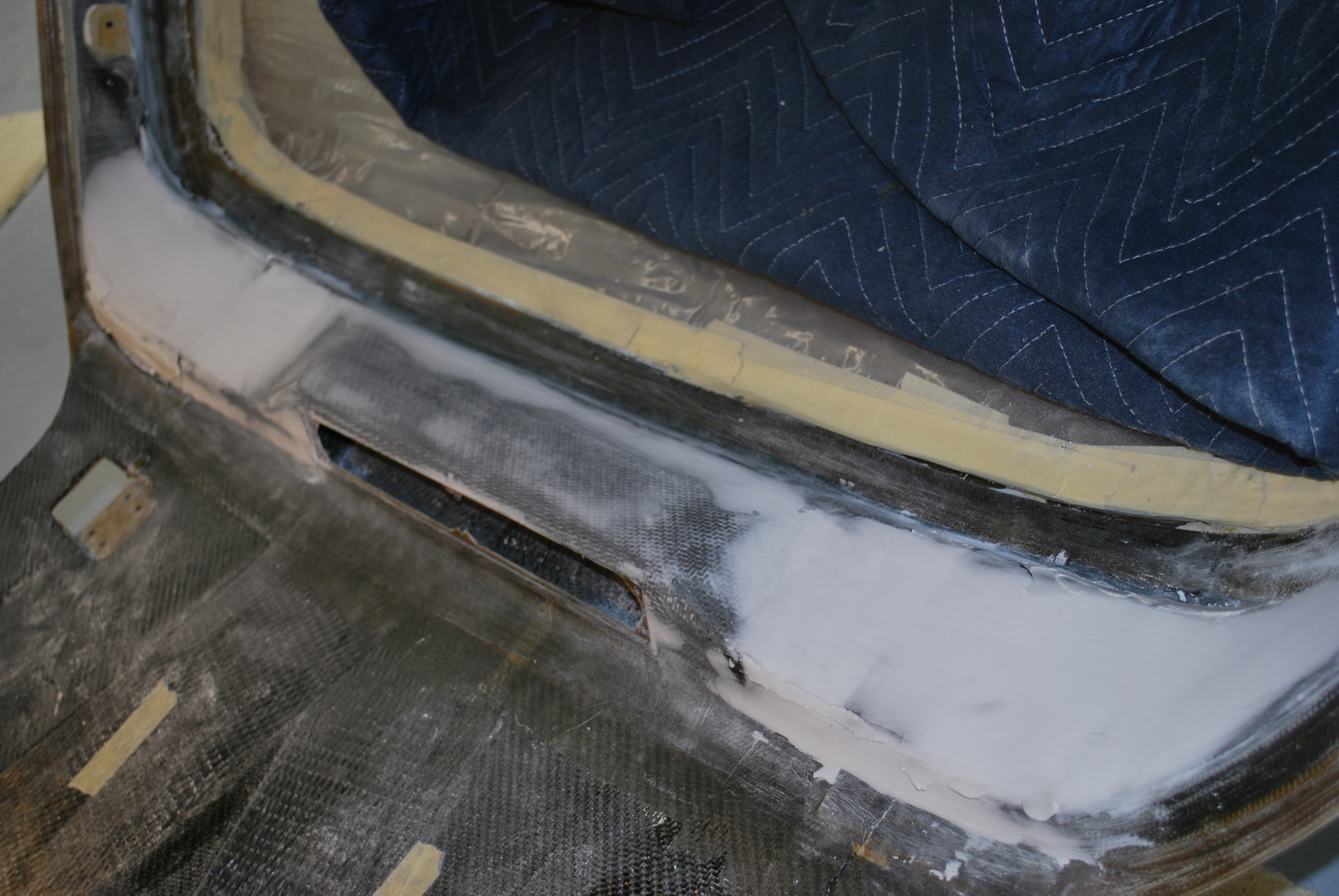
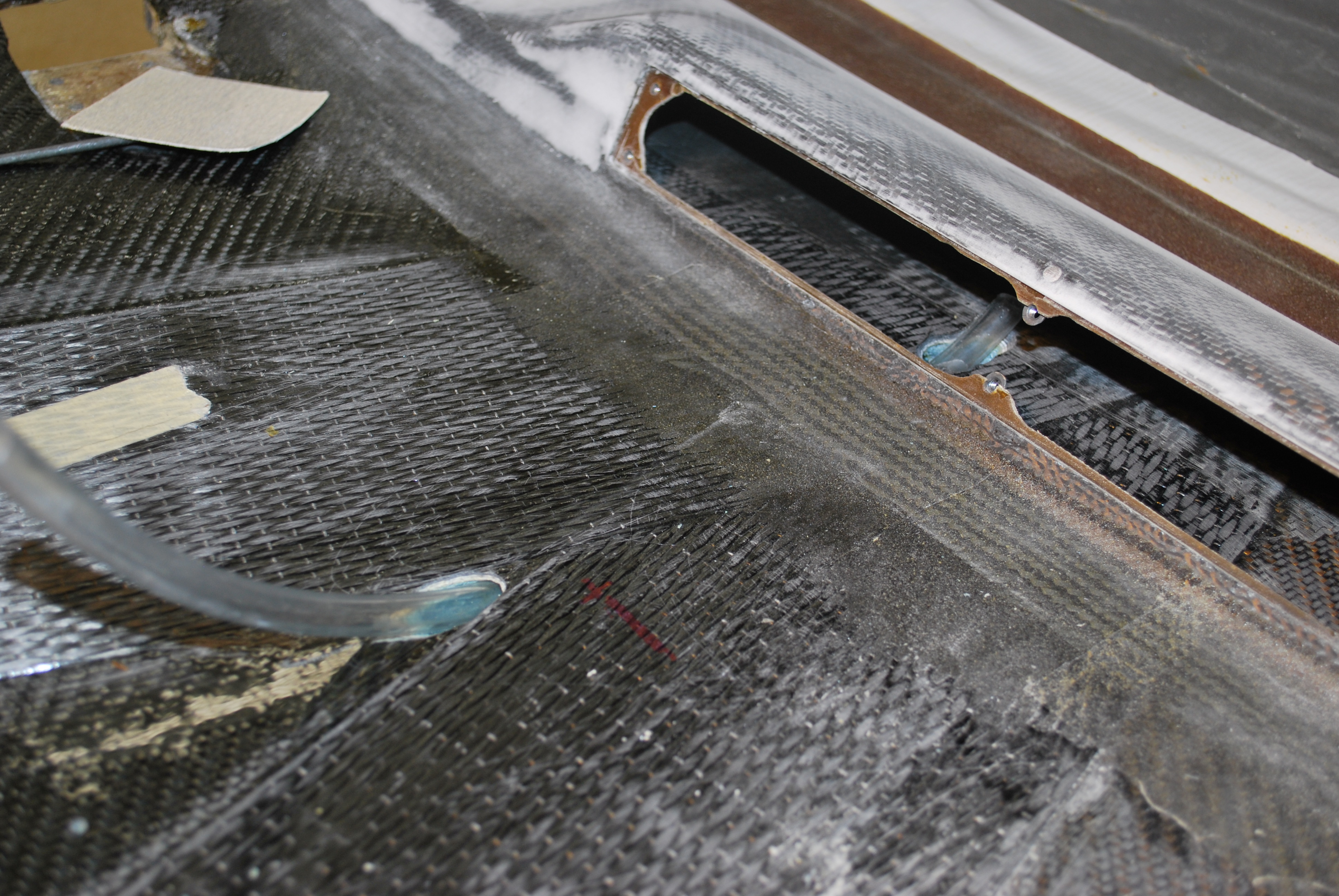
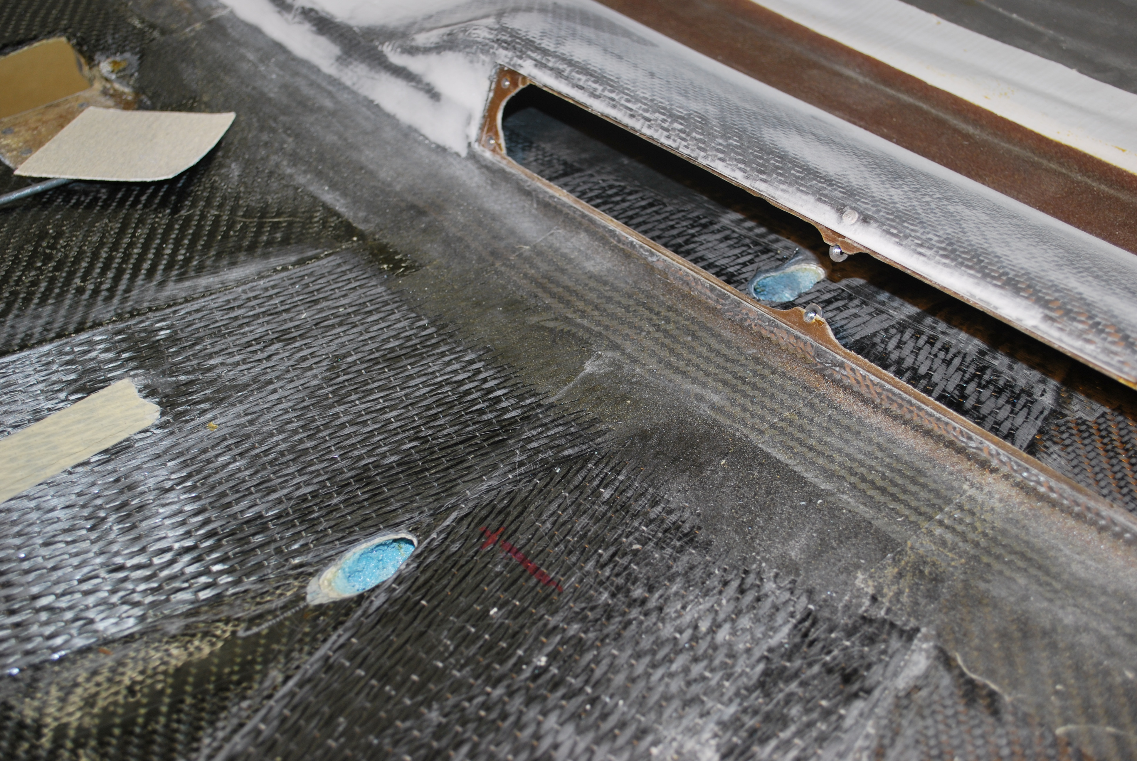
The NACA ducts that I installed nearly two years ago need to be reinforced from the inside. So a couple layers of BID around the edges of the NACAs and the fresh air duct.

Now comes the big stuff. I’m not going with the diagonal shoulder belt system that the factory sells (and is found in most cars); a lap belt and a diagonal shoulder harness. Instead, I’m going with a 4-point style with a lap belt and two shoulder harnesses that connect to a center buckle.

The problem here is that with the fast build, the factory puts in the hardpoint for a diagonal shoulder harness (this is the stuff that you don’t think about when you’re starting all of this). So I’m going to have to completely remove the B-pillar/overhead beam.

2009-10-13 2250 DSC_0365

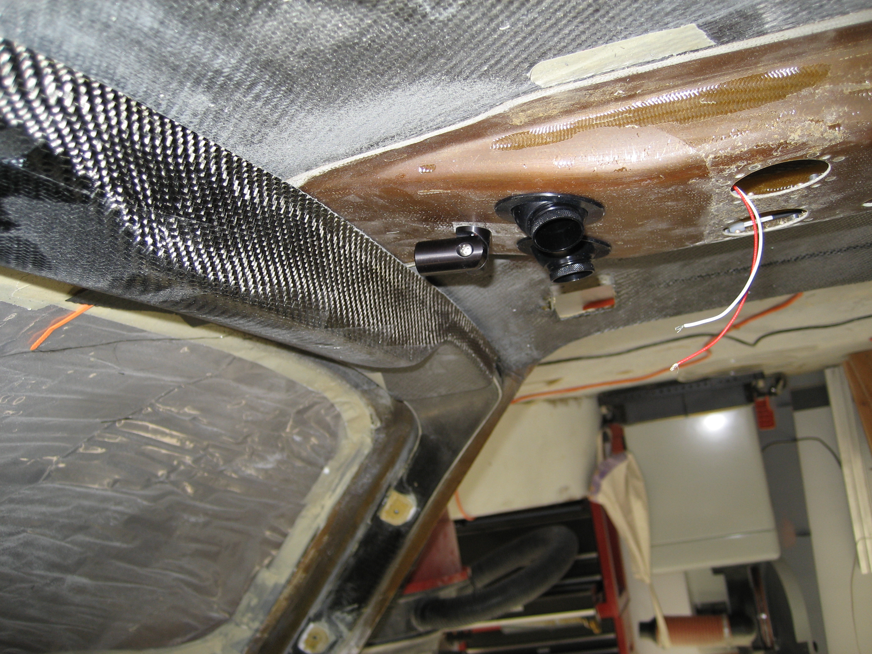
This is looking up at the roof. At the bottom-center is the top of the pilot side door opening. Top-center is the top of the co-pilot door opening. On the left side of these door openings is the overhead beam. This overhead beam (and the B-pillars which run down the side in back of the door openings) are made of carbon fiber. In order to get a hardpoint for the shoulder harnesses to mount to, I was going to have to remove this, install the hardpoint and re-install it. That’s when I made a couple discoveries. 


  • The B-pillars and overhear beam are not a single unit. They are three separate pieces.
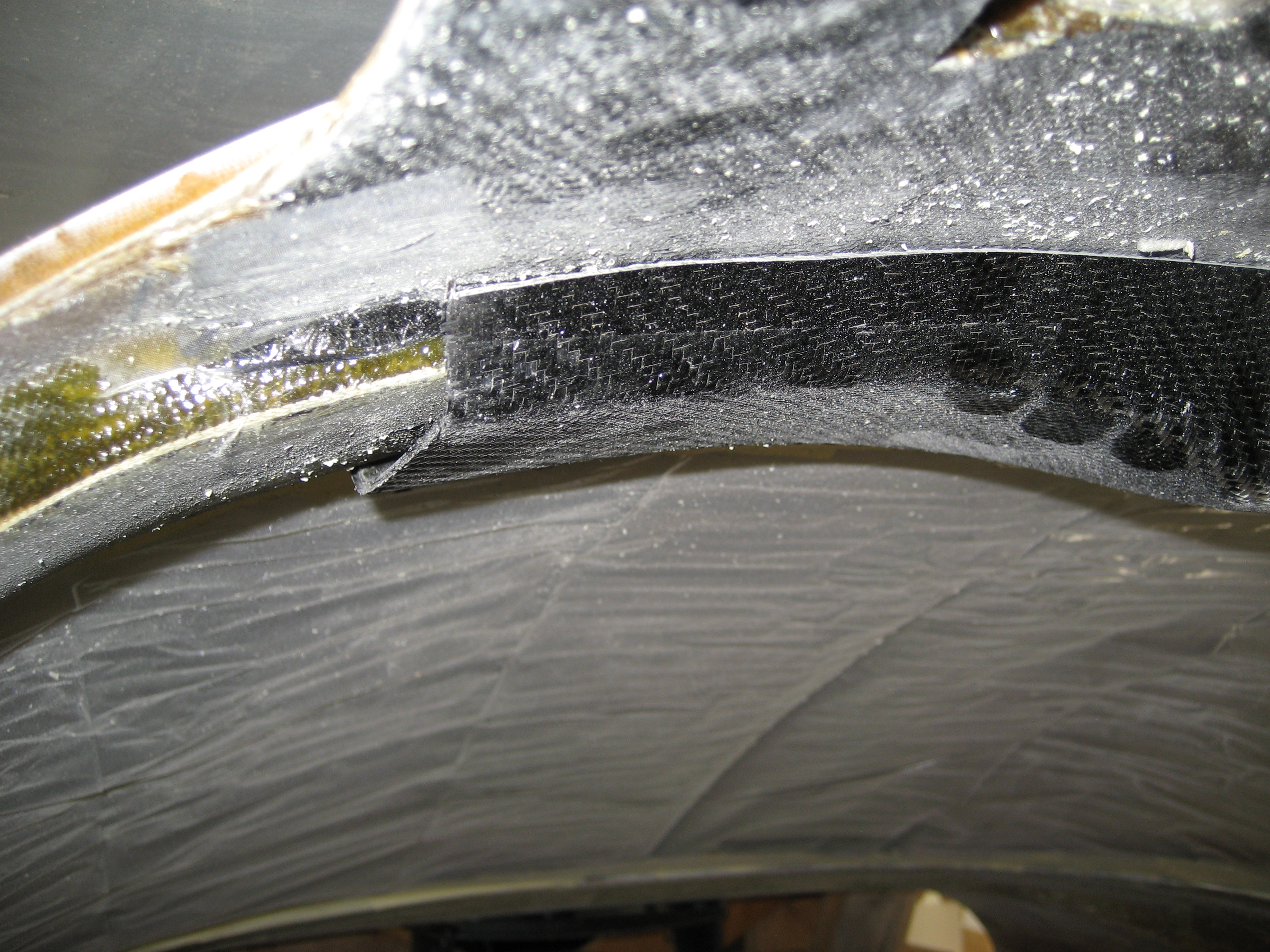
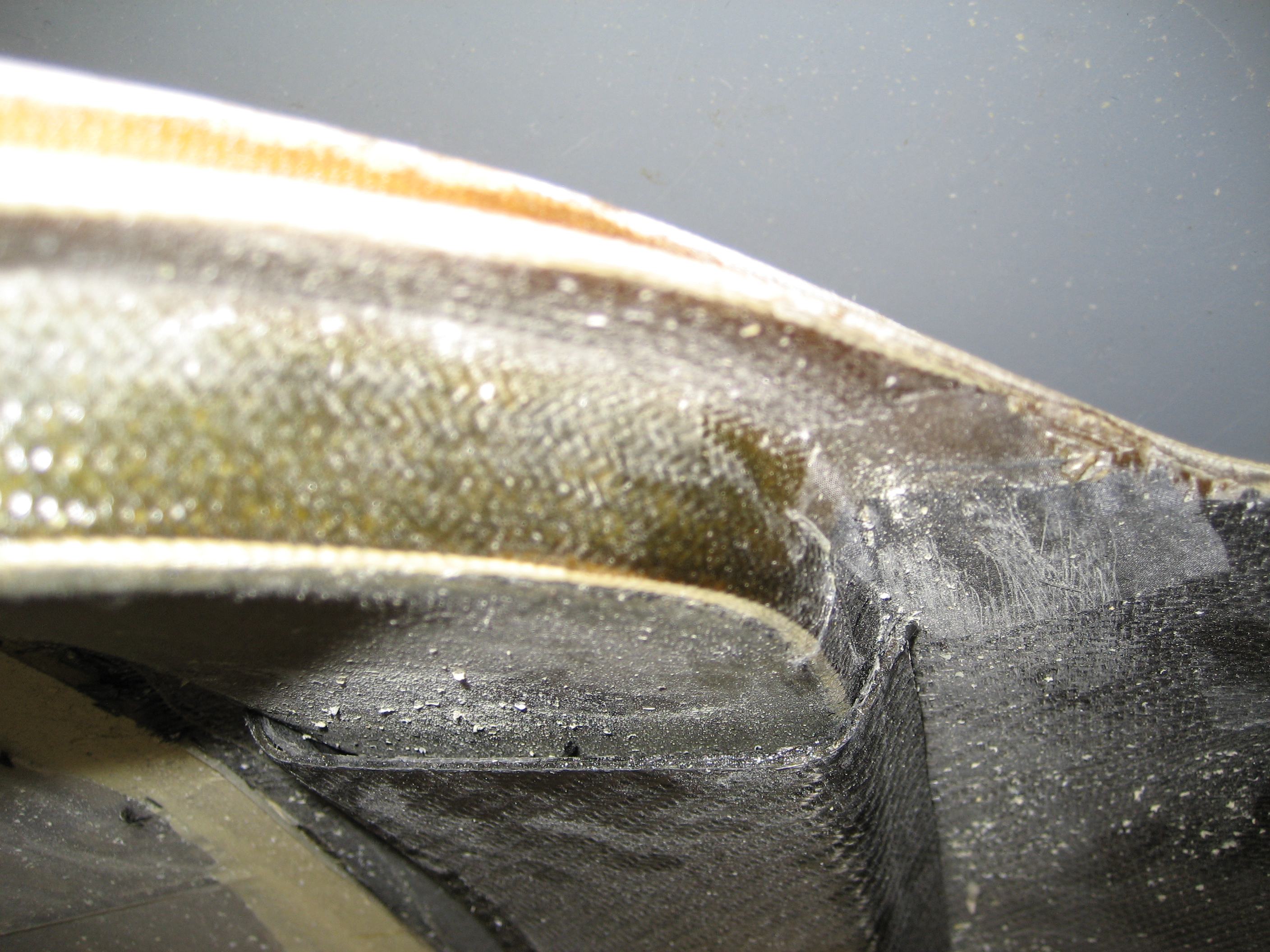
  • Where they are tie in is not the most impressive union I’ve ever seen.
  • The roof has a layer of carbon fiber BID… but only one layer. (Notice in the previous picture that instead of solid black, you can see some “tan” between the rear beam and the windshield.)


2009-10-24 1245 IMG_9457
Here’s the joint between one of the B-pillars and the overhead beam.

2009-10-24 1246 IMG_9458

And here’s a closeup. No reinforcing layups. Just some epoxy.

The first thing to do is remove the overhead beam. To do this, I scored the 2-BID layup where the beam meets the roof. Then using a putty knife, I separated the BID from the beam at one end and then literally peeled it away from the beam. Then repeat for the roof. Next I made a couple small cuts at the joints on each end, a couple whacks with a chisel and the beam came right out. 

      2009-10-29 2007 IMG_9476

Next I smoothed out any rough areas and sanded the entire forward roof area and lay down an (additional) layer of carbon fiber BID.

2009-10-30 0804 IMG_9479

Once that cured, I decided to do an additional task. Most builders have a hard time getting the doors to fit after installing the engine. This is due to the weight of the engine causing the fuselage shape to change slightly. A few builders have installed some diagonal layups on the roof from the rear to the front to prevent the distortion. I used two plys of a fairly thick carbon fiber UNI that will help with the distortion and will add to the strength of the roof. 

2009-11-01 0948 IMG_94832009-11-01 0948 IMG_9484

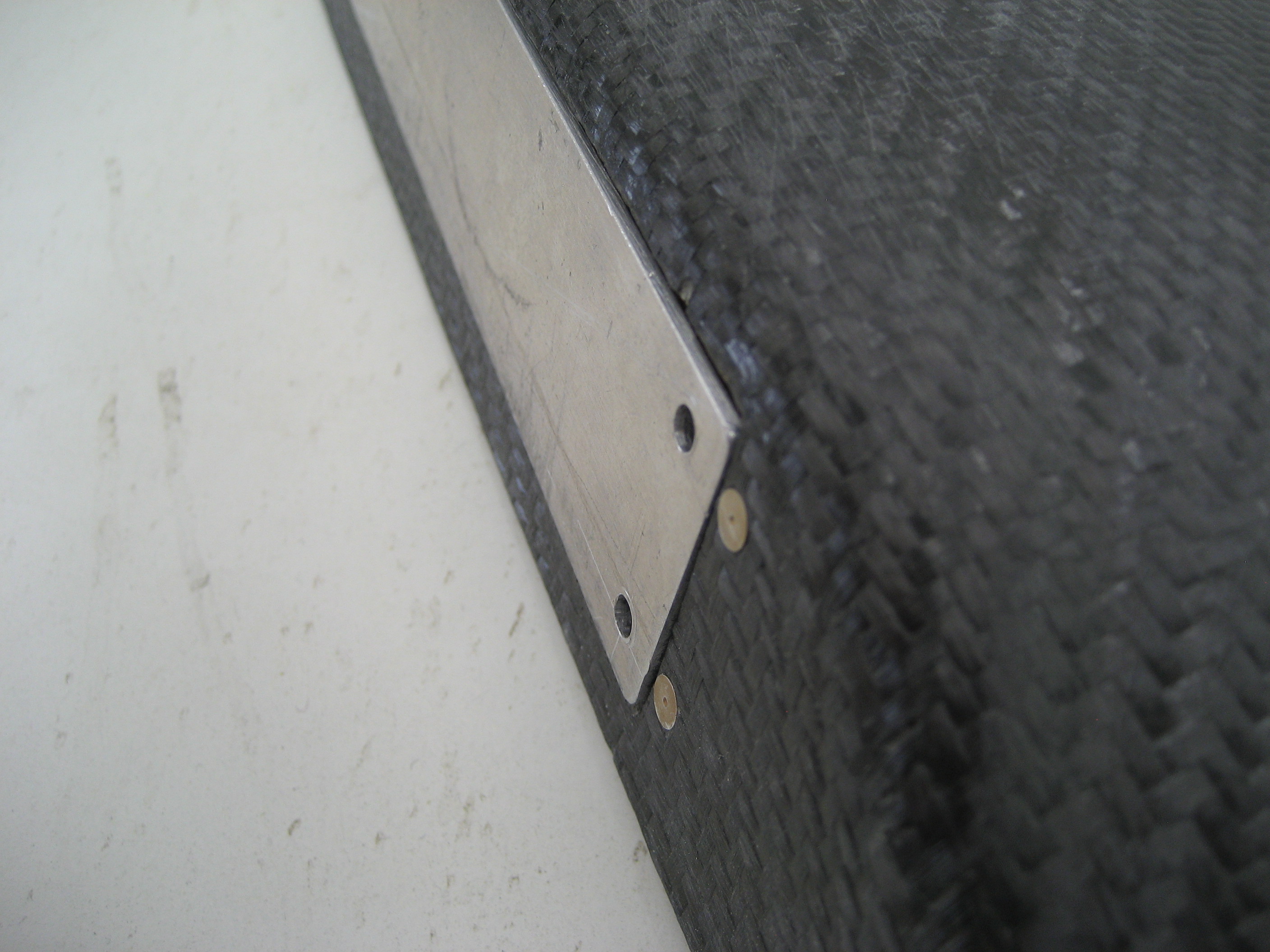
Next I needed to locate where the hardpoint for the new (improved) shoulder harness will be. I did this with a plumb bob and a tape measure. The hardpoints for the diagonal shoulder harness is a piece of 2″x4″ wood. Two problems with that method for the new hardpoint. #1 is that the B-pillar is much deeper than the overhead beam (the beam is only 5/8″ deep) and #2 is the factory hardpoint uses a bolt sticking out. So I’m going to use a 3″ x 4″ x 1/2″ piece of aluminum that’s drilled and tapped. For most hardpoints, they use 2″ x 2″ x 1/8″ so mine will be much more substantial.

Here’s my hardpoint and the standard sized hardpoint.

2009-11-03 1356 IMG_94882009-11-03 1356 IMG_9489

Once the hardpoints are secured with structural epoxy, I drilled and tapped them.

2009-11-04 0925 IMG_9490

Before installing the beam I glued down a small square of titanium on the ceiling where the bolt for the hardpoint would come through. Just in case a too-long bolt was used, I didn’t want it going through the skin.

2009-11-04 0925 IMG_9492

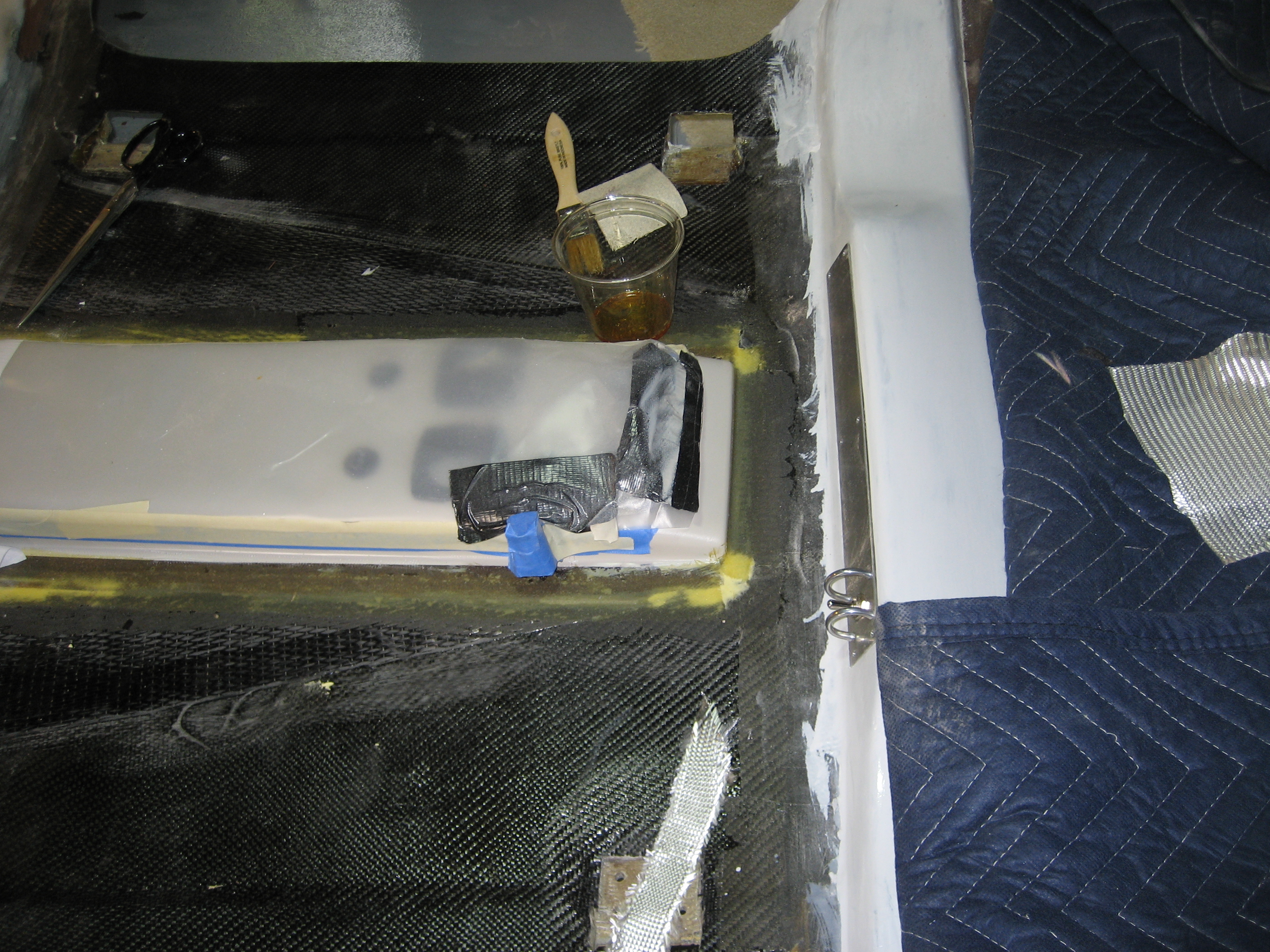
I need to bond the beam in place. I want the overhead beam to become part of the of the B-Pillars to create a seamless rollcage. So I took 2 layers of leftover carbon UNI and inserted them into the ends of the B-Pillar. I then stuffed some foam under the layups to force it into contact with the inside of the B-Pillar.

2009-11-04 1024 IMG_9493

Then I applied some structural epoxy to the bottom edge of the beam and pushed into position. The foam under the layups will also force it into contact with the inside of the overhead beam. I then put the beam in place with a couple bricks on top to hold in place while the epoxy setup. Then I used some more leftover carbon BID over the seam with the B-Pillars and over the beam and onto the roof.

 2009-11-11 1615 IMG_9528


6.9 Overhead Fresh Air Plenum

This entry is part 34 of 42 in the series 06 - Fuselage

Here you can see the duct for the fresh air in between the two engine cooling NACA ducts.

IMG_5734

On the inside, there’s a plenum that runs from the rear up to the front. I’m going to install four eyeball vents (one for each seat) and four lights. The electrical lines for the lights will also be in the plenum. Determining the location of the vents and lights will be a little tricky since the seats aren’t in and the airplane is upside down so I’ve got to guesstimate their location.

Here’s one of the vents that I’m going to be using.

2009-11-11 1616 IMG_9530

I forgot to get a picture of the plenum before cutting the holes for the lights and vents. But here’s the front of the plenum after the holes are drilled for the vents with one of the vents installed.

2009-11-11 1617 IMG_9532

Here it is mounted in the plenum.

2009-11-11 1617 IMG_9533

Oops. Going to need to be modified. 🙂

Before and after.

2009-11-11 1618 IMG_9534

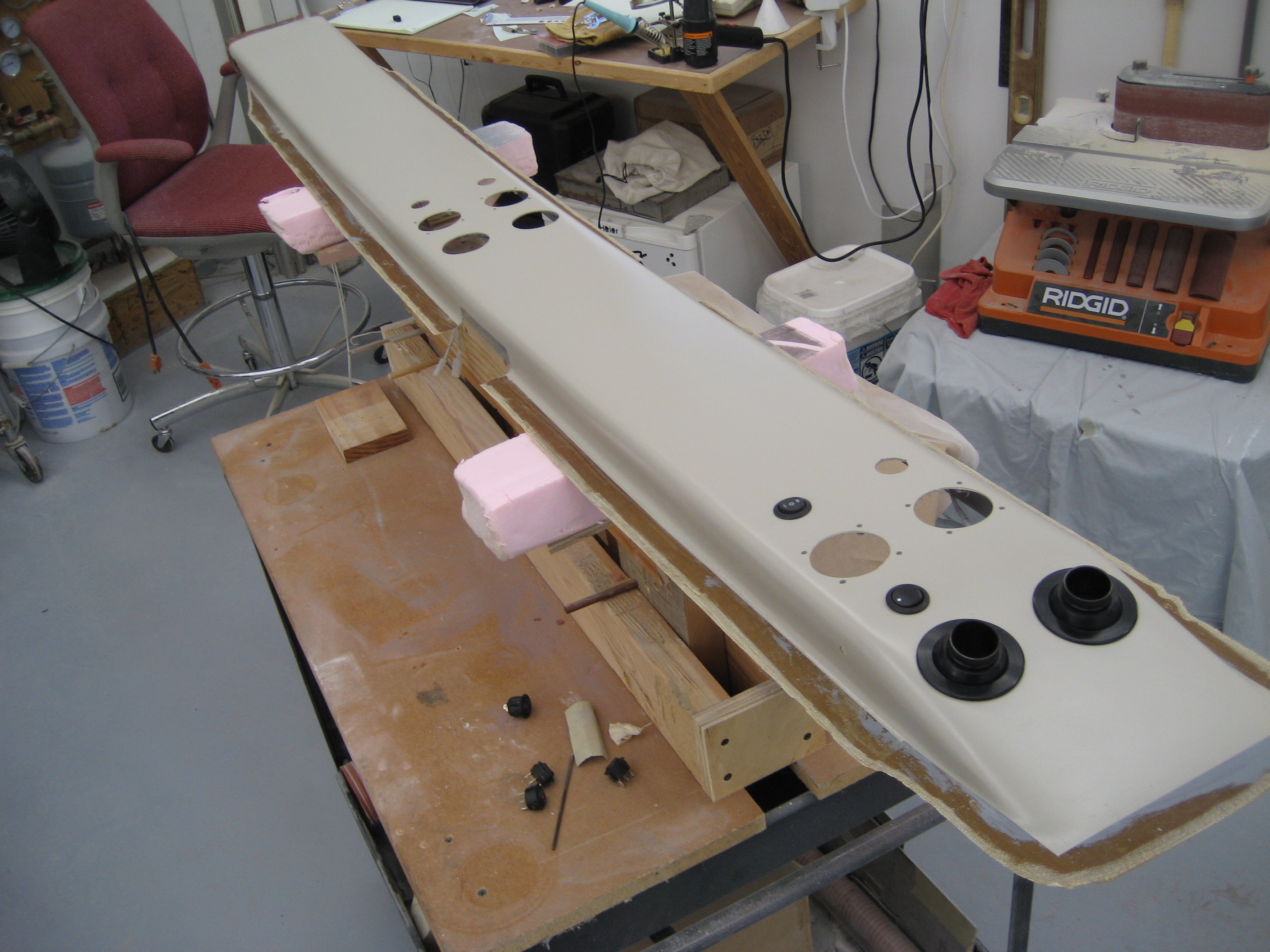
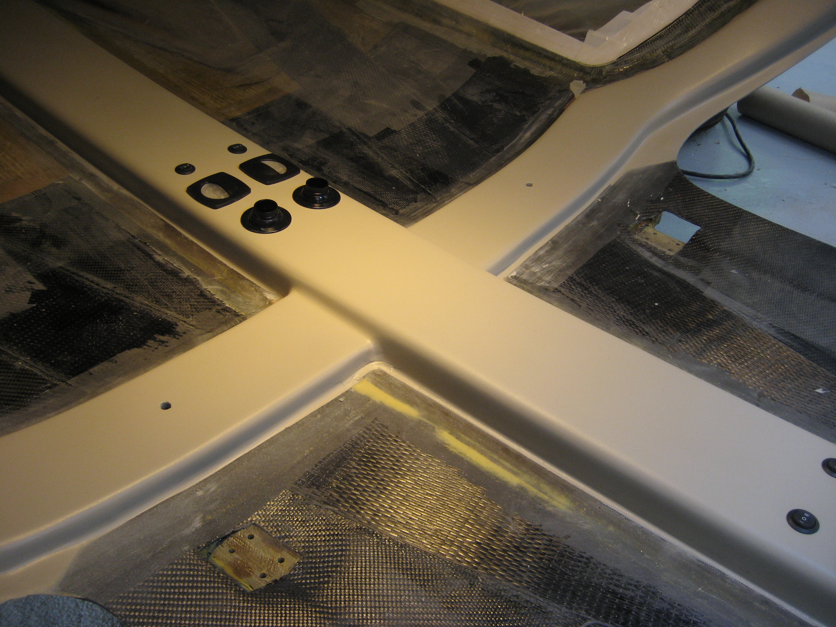
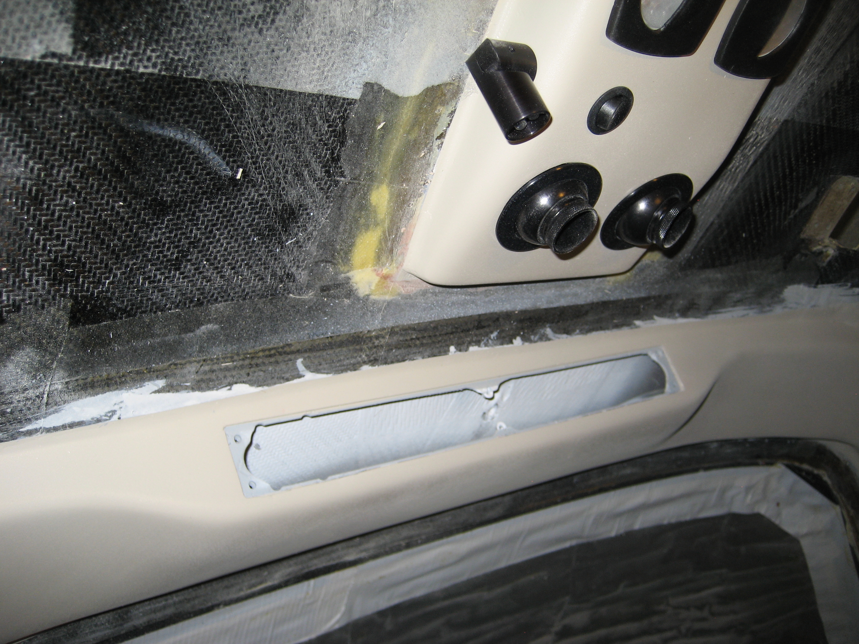
Here’s the plenum with the openings for the vents, lights and switches.

2009-11-15 0855 IMG_9535

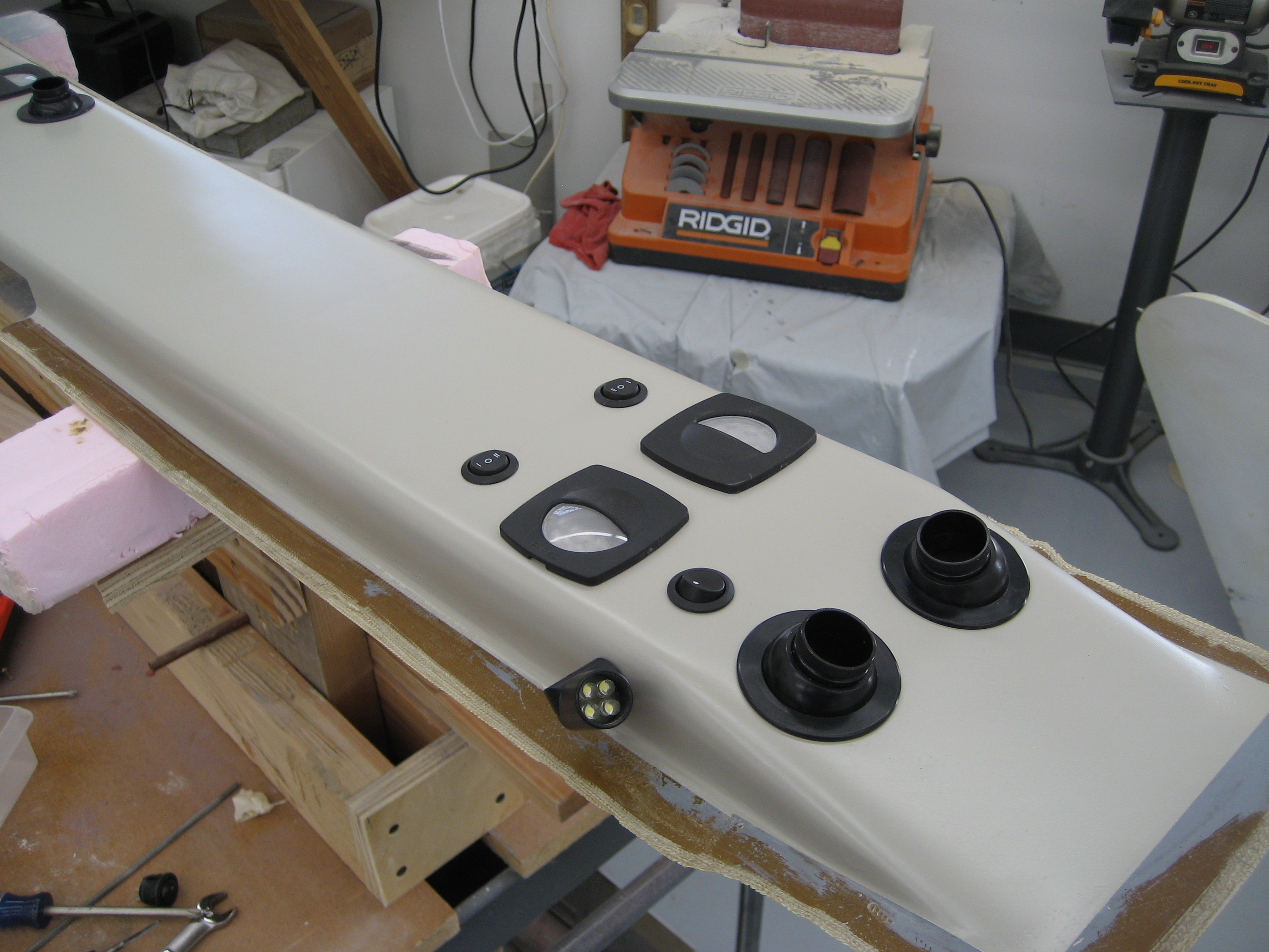
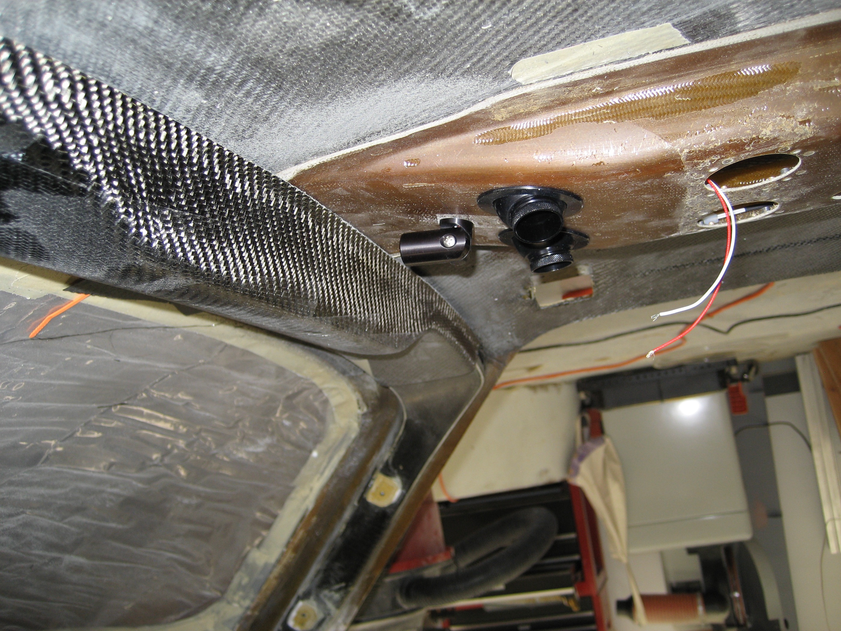
The plenum with the vent, light and switch for the left rear seat.

2009-11-15 0856 IMG_9536

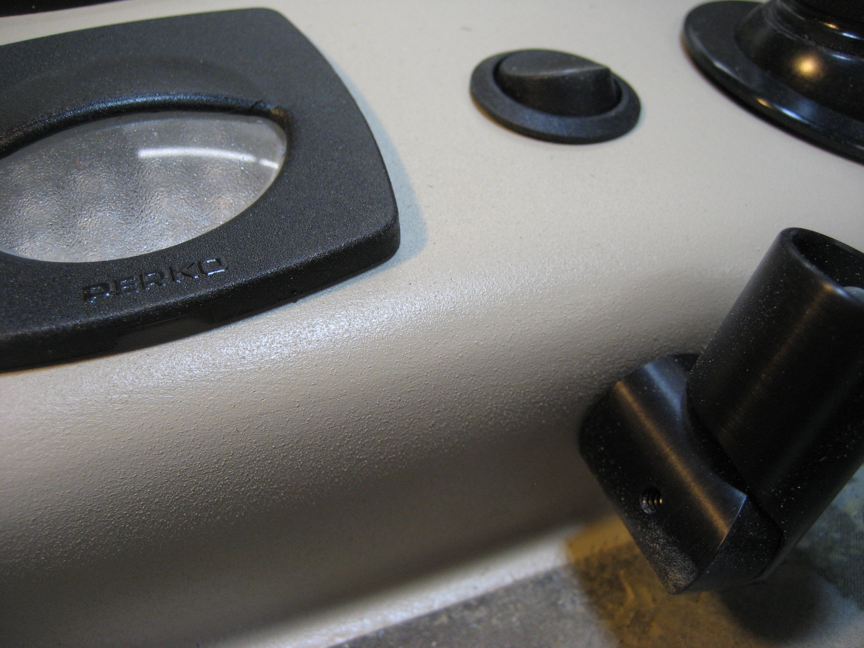
Closeup of the previous position.

2009-11-15 0856 IMG_9537

The lights are attached with 4 6-32 screws so I had to drill holes for the screws and nutplates.

2009-11-15 0931 IMG_9543

Can’t leave well enough alone. After talking with my A&P (Airframe and Powerplant mechanic) who used to work for United keeping their airplanes flying, he suggested an “all on” switch. A single switch that will turn on all the lights. Sounded like a good idea but it will require redesigning the lighting circuit board. This time, I decided to let the company that provides the design software make the board. It cost about $10 per board so I figured that I would try it.  While I was at it, I added a fourth white LED and used a single resistor for both sets of lights.

Here’s the new circuit board.

2009-11-18 1548 IMG_9553

Mounted and wired.

2009-11-18 1547 IMG_9551

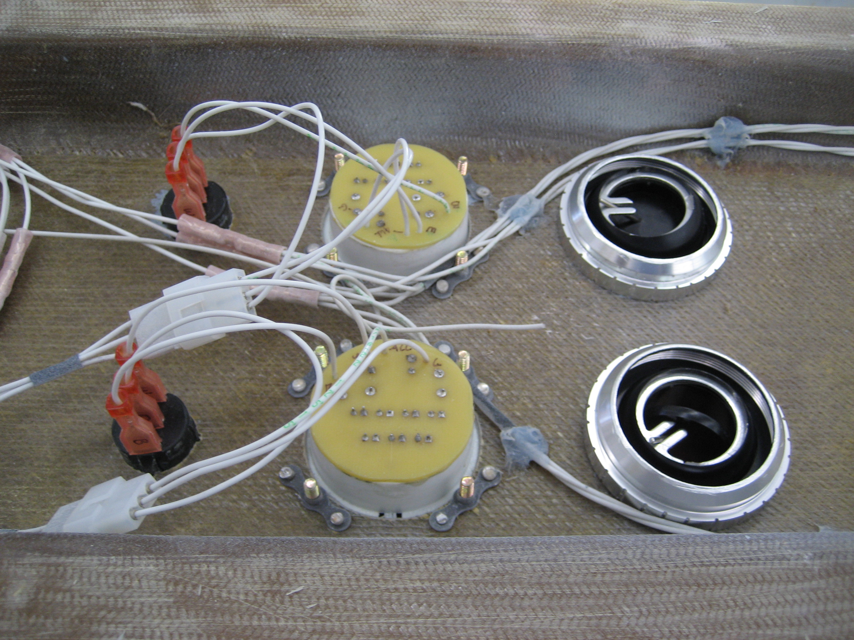
From the inside.

2009-11-18 1548 IMG_9552

Test run.

2009-11-17 1919 IMG_9550

More Plenum Work

Because the air intake is on the top of the fuselage, water will be able to enter the plenum. So a drain is needed at the back of the plenum.

2009-11-23 1451 IMG_9569

Then I put a bulkhead just aft of the drain so no water would pool in the plenum.

2009-11-23 1452 IMG_9571

Finally, to prevent water from being forced up front and out the vents, I installed a small “half bulkhead” (a dam, if you will) between the intake and the vents up front.

2009-11-23 1452 IMG_9570

I was going to add the swivel map light at the front of the plenum. This would illuminate the overhead switch panel and could be used for a map light. For some reason, I decided to check the location. Good thing I did…

2009-12-17 1045 IMG_9580

2009-12-17 1045 IMG_9581

Two things wrong here: 1) it’s so close to the panel that it would only be able to illuminate a fraction of the panel and 2) it will interfere with accessing the switches. So it I decided to move it to the side and a couple inches back. While it won’t light the panel like I thought, I can still use it as a map light.

Before installing, I still need to paint it.

6.9 Overhead Fresh Air Plenum Painting

This entry is part 35 of 42 in the series 06 - Fuselage

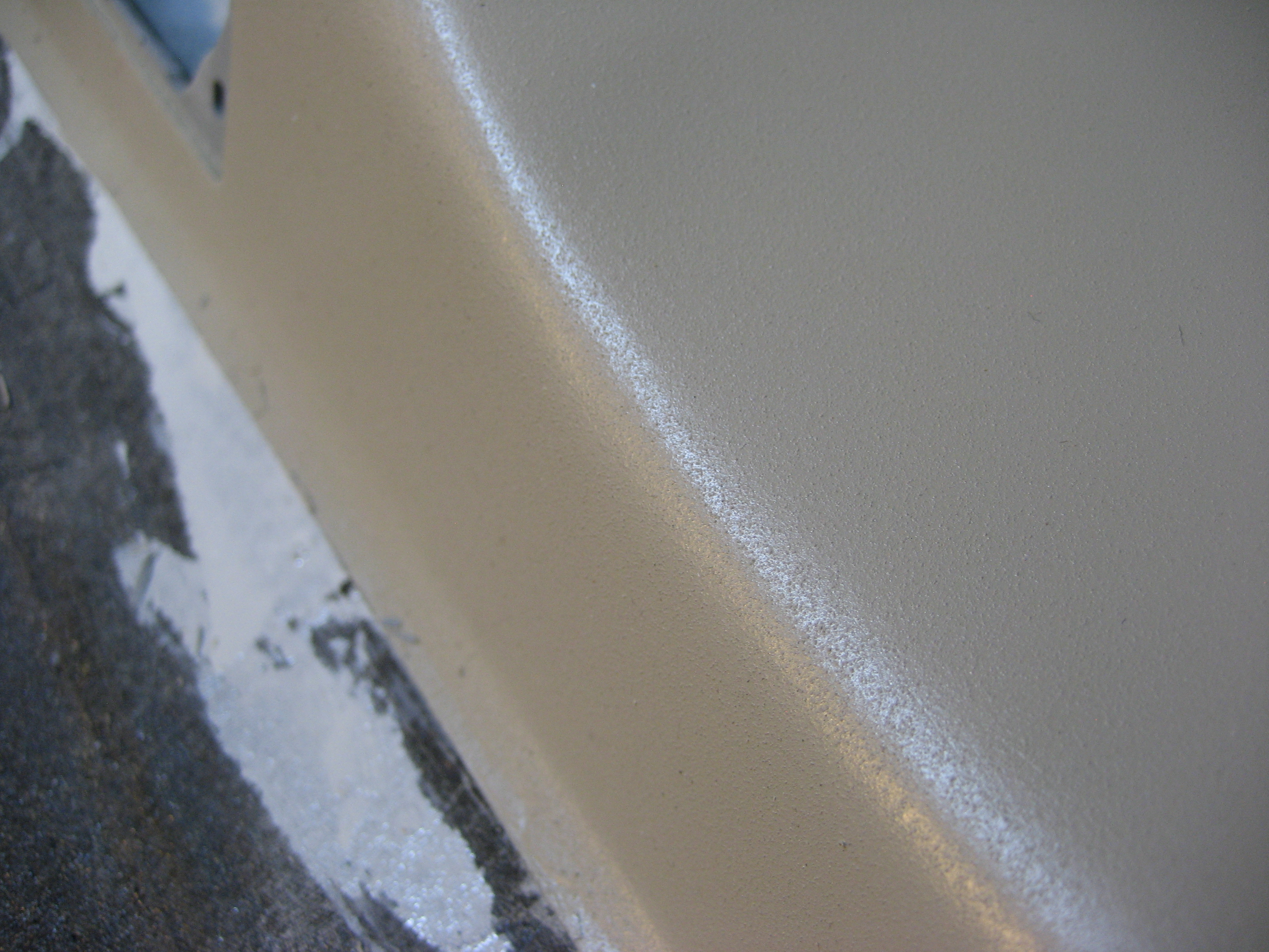
Many builders cover the A & B pillars and overhead fresh air plenum. I decided to follow Andy Millin’s example and and use paint for those surfaces. He used a satin finish on his plane.  But the amount of finish work required to get a good result was rather daunting.  So I selected a texture that did a much better job at hiding sins.

So after very little finishing work I sprayed the plenum. The results were very nice.

2010-02-11 0837 IMG_01172010-02-11 0837 IMG_0116


2010-02-11 0958 IMG_01222010-02-11 0958 IMG_0121

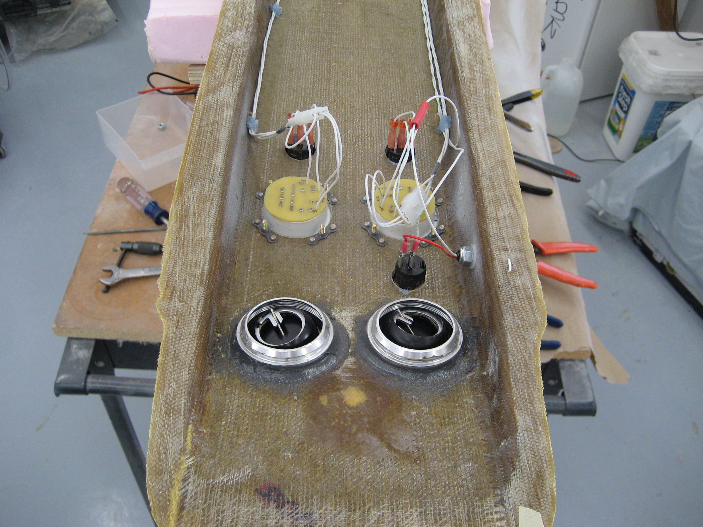
Inside wiring for the lights

2010-02-11 0957 IMG_0120 2010-02-11 0957 IMG_0119 2010-02-11 0957 IMG_0118

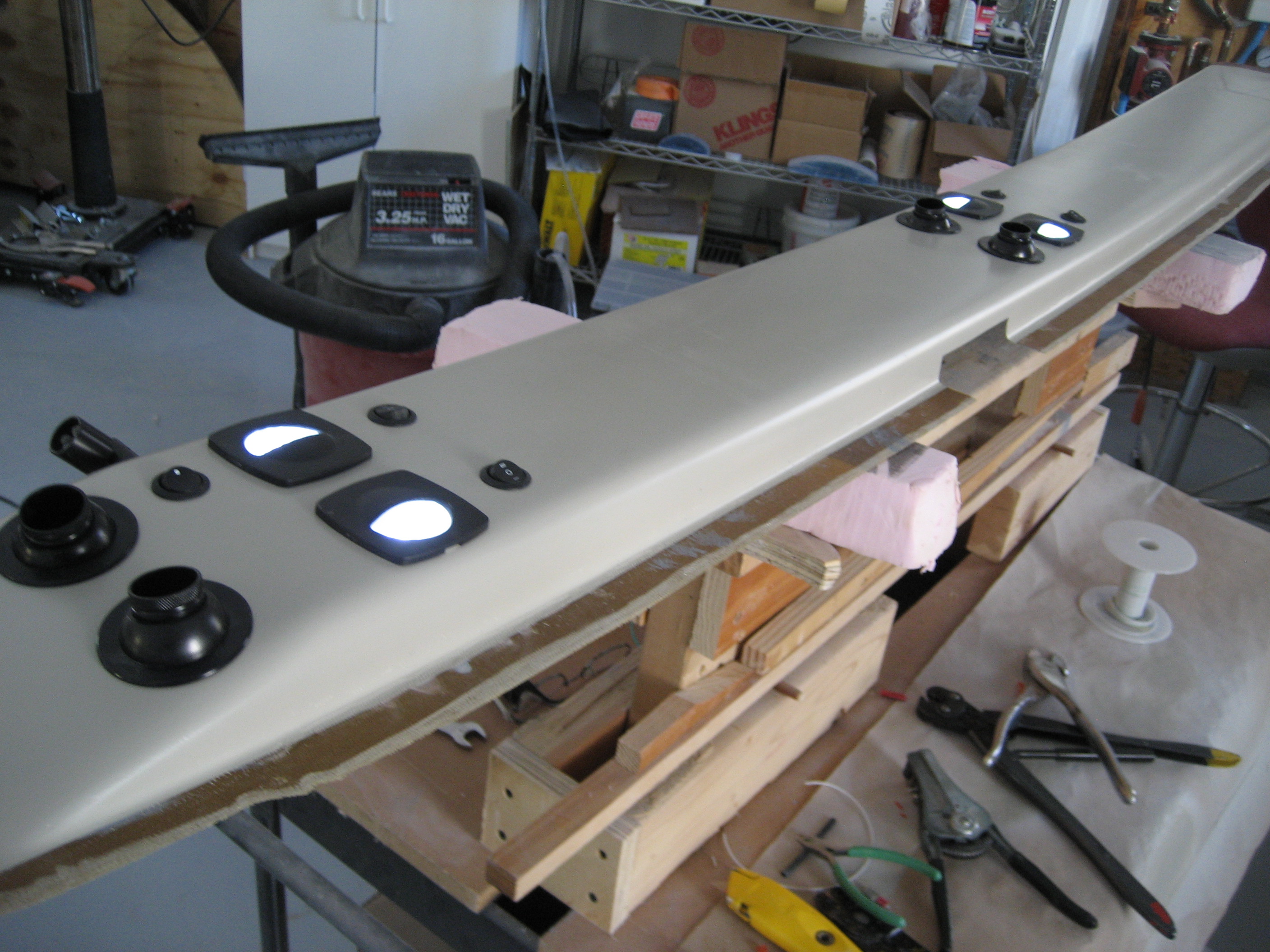
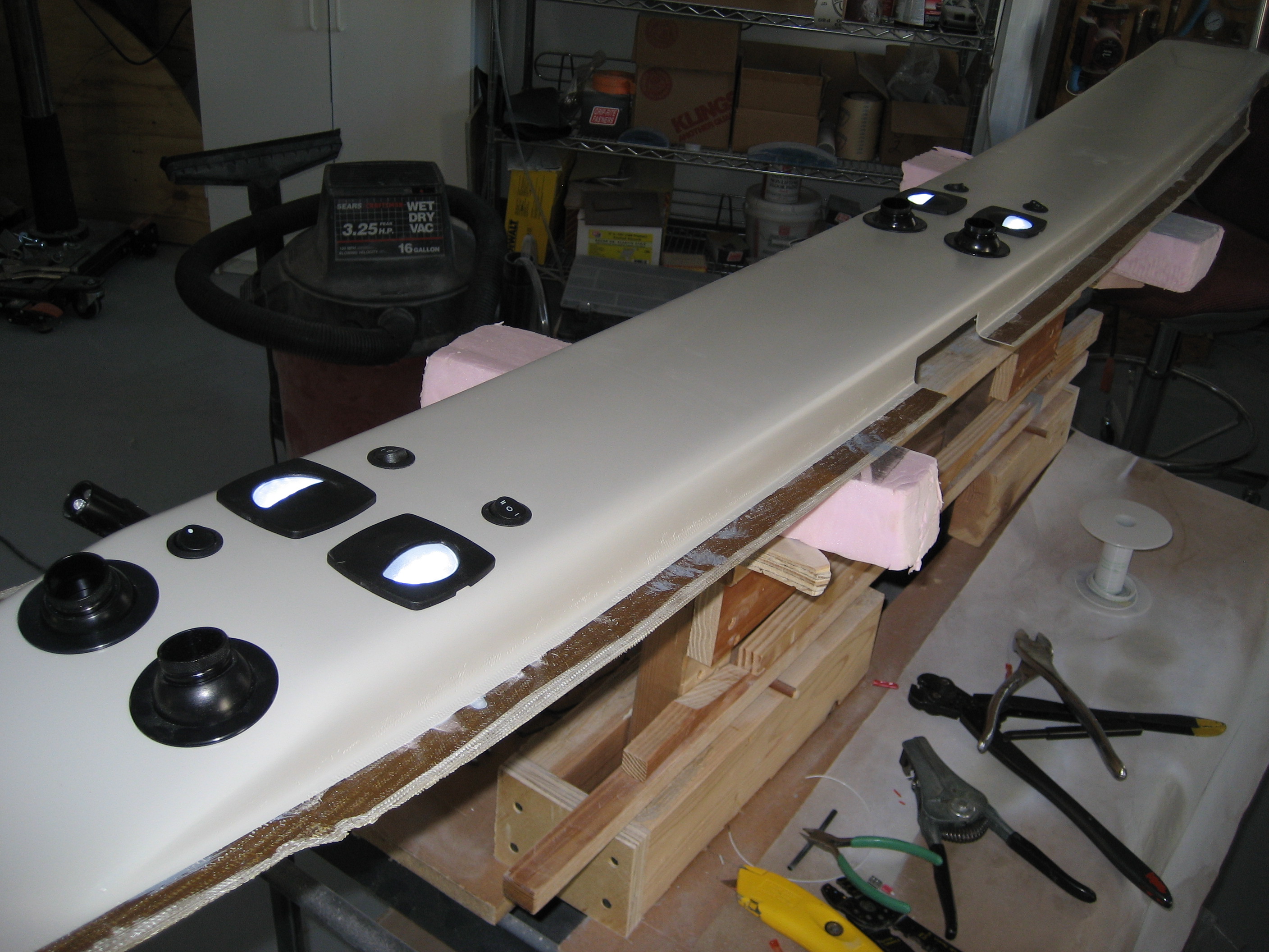
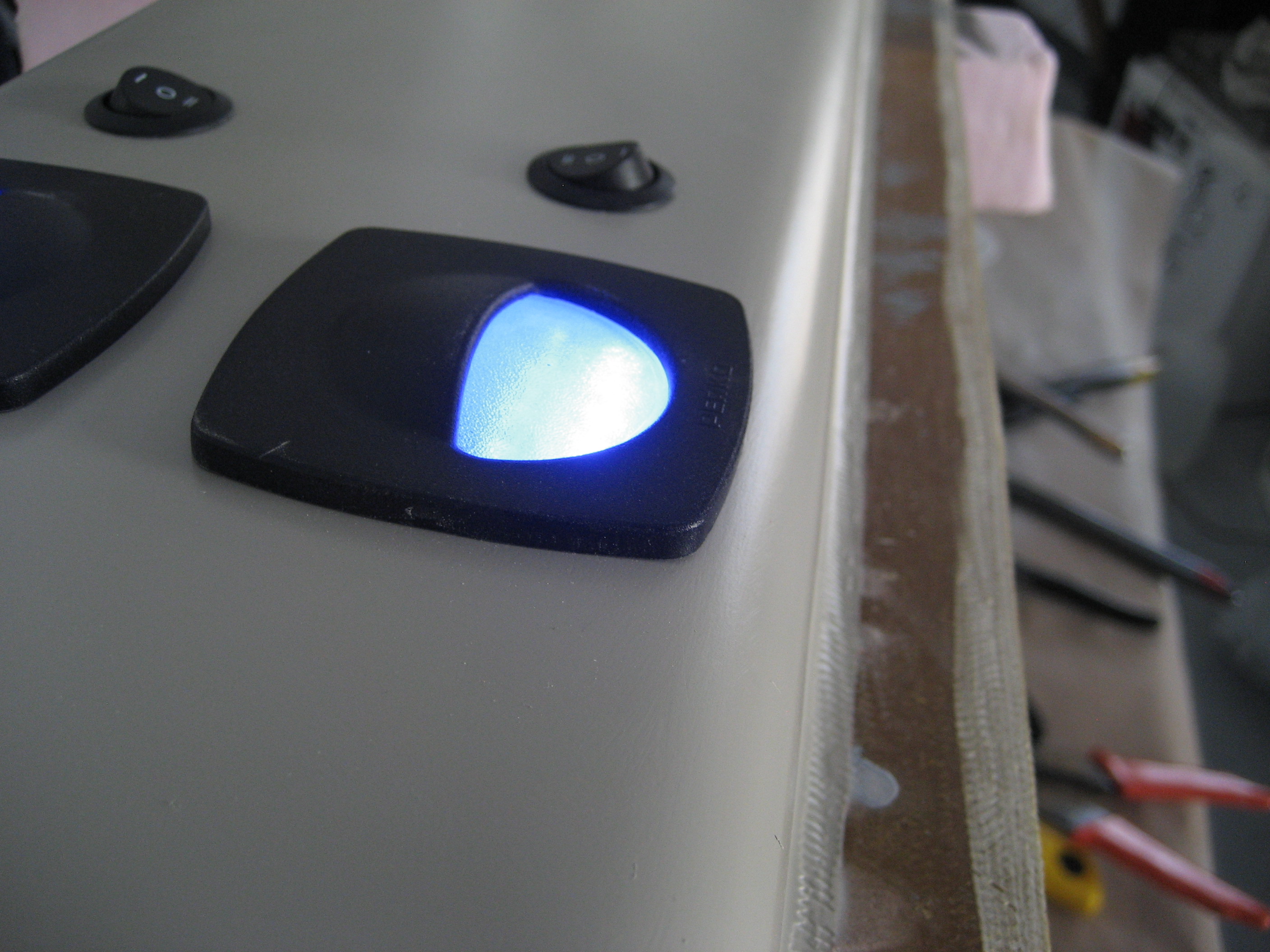
And a quick lighting test.

2010-02-11 1003 IMG_01252010-02-11 1003 IMG_01242010-02-11 1003 IMG_01232010-02-11 1004 IMG_0126

6.0 A-Pillar Beam (Overhead Switch Panel)

This entry is part 36 of 42 in the series 06 - Fuselage

The overhead switch panel is the beam which joins the A-pillars across the top. Just like the B-pillar beam, I added a couple BID of carbon fiber inside and out to increase the strength. Next, I had to decide how to join it to the A-Pillars. Here you can see that it doesn’t quite line up.

2010-01-13 0842 IMG_95992010-01-13 0842 IMG_9600

I could mount it as is and transition it or I could cut it down. As I’m taller than the average person, leaving it as is mean that it hangs lower. This COULD become a visual obstruction. It also means a bunch more work where it transitions to the A-pillar. On the down side to cutting it to fit is that I’ll have less room to work with when installing switches.

So I cut it down until if was even with the A-pillars. Then like I did with the B-pillar beam, I made a flange out of carbon fiber uni using the foam rubber trick. Here’s the result on the pilot side (the nylon tube is for routing wires).

2010-02-15 1107 IMG_0128
 Before permanently installing the beam, I needed to cut an opening and create a flange for where the switches would go.

Once again, here’s the beam before the opening:

2009-12-17 1045 IMG_9581

And here it is after:

2010-02-15 1107 IMG_0129
Closeup of the flange and nutplates:
2010-02-15 1108 IMG_0130

With a blank aluminum panel in place:
2010-02-15 1108 IMG_0131

Closeup of the panel:
2010-02-15 1109 IMG_0132

To mount the beam, I used structural adhesive on the inside and a couple layers of carbon fiber uni on the outside of the seam and BID along the front and rear.

This is the beam after mounting and during filling.

2010-03-05 0118 DSC_206

Stuff you don’t think of until it’s (almost) too late.

Andy Millin came up with an absolutely brilliant thought. Rather than run the wiring for the plenum lights all the way from the front to the aft wall of the cabin, then up to the plenum, then forward to the lights; Why not create a tunnel between the inner and outer skin of the roof from the switch panel to the plenum? It’s only 4 inches instead of 20 feet! He did his BEFORE installing the overhead beam. But where there’s a will, there’s a way.

I drilled two holes; one where the forward edge of the plenum will be and the other behind the switch panel.

2010-03-09 1012 DSC_210

Then I started tunneling. Using a sharpened clothes hanger and some other MacGuyver-type tools, I was able to break though. Then I inserted at length of nylon tubing.

2010-03-09 1012 DSC_211

Then I filled the area around the tube with epoxy/micro.
2010-03-09 1047 DSC_2122010-03-09 1048 DSC_2132010-03-09 1048 DSC_214
Once the micro cured, I cut the tubing flush.

6.9 Overhead Fresh Air Plenum Modification

This entry is part 15 of 42 in the series 06 - Fuselage

Plenum Modification

The front of the overhead plenum tapers down to the roof. Here’s this picture again where you can see what I mean.
2009-12-17 1045 IMG_9581-1

It occurred to me (after painting the darn thing) that doing the interior is going to be a challenge. Most of the ceiling is covered with a thin flexible board (almost like cardboard) which is covered with fabric or vinyl or leather or whatever you want. But what to do at that taper?

So I decided to lop it off and square is up. After that, I had to paint the area and blend it in with the existing paint.
2010-03-20 1026 IMG_0370 (Large)2010-03-20 1026 IMG_0371 (Large)

6.3.2 Front Seat Assembly

This entry is part 37 of 42 in the series 06 - Fuselage

The seats consist of a pan (the part you sit on), a seatback and a hinge. The front seats use a new adjustable hinge which lets you change the angle of the seatback. The rear seats have a fixed angle.

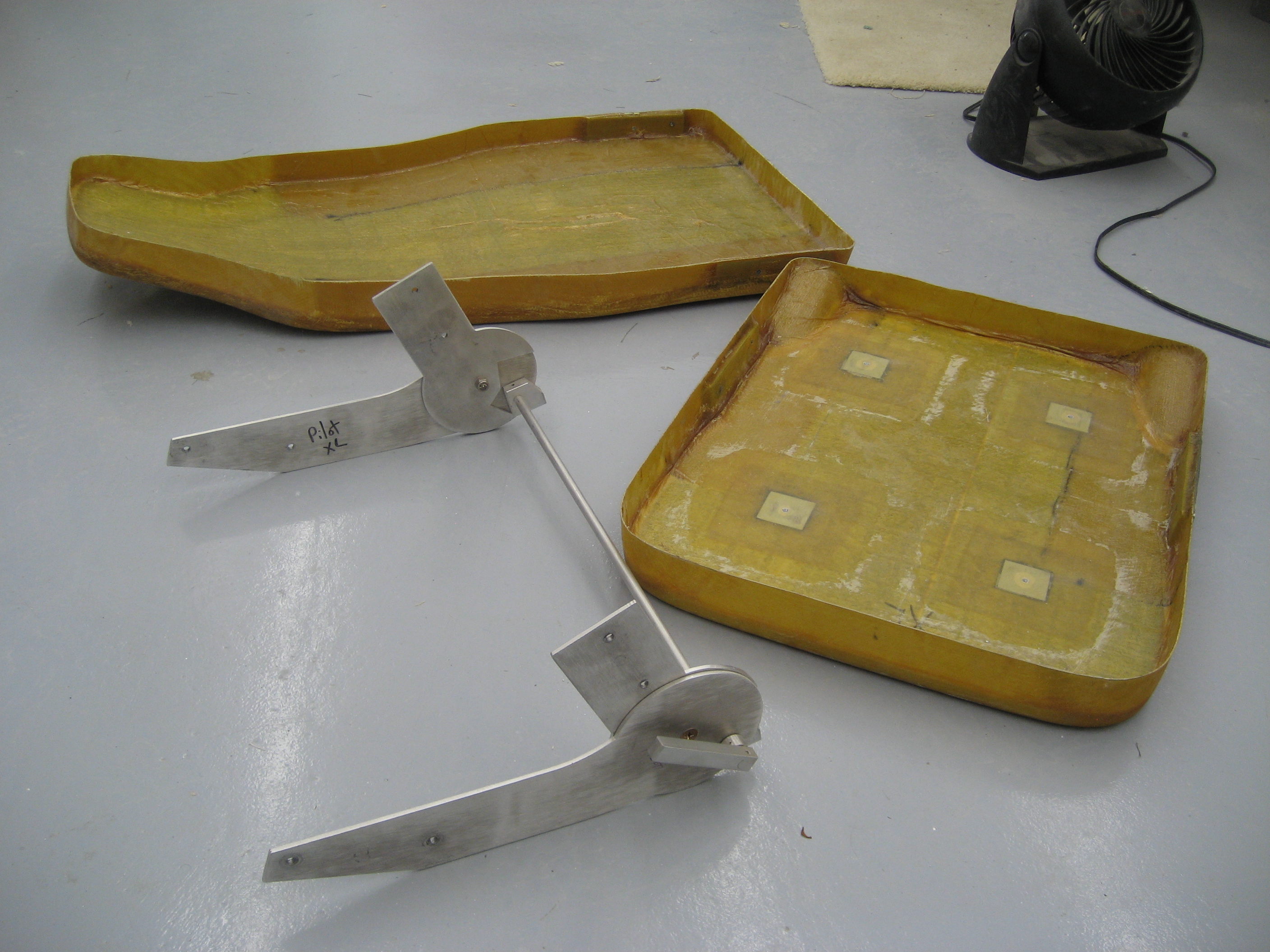
Here are the three parts for one of the front seats. There’s also a rail (not pictured) that the seats mount to which allows you to slide the seat front-to-rear.

2010-06-07 1429 IMG_0594

Now the this adjustable hinge is new and it doesn’t fit to the seat pan very well.

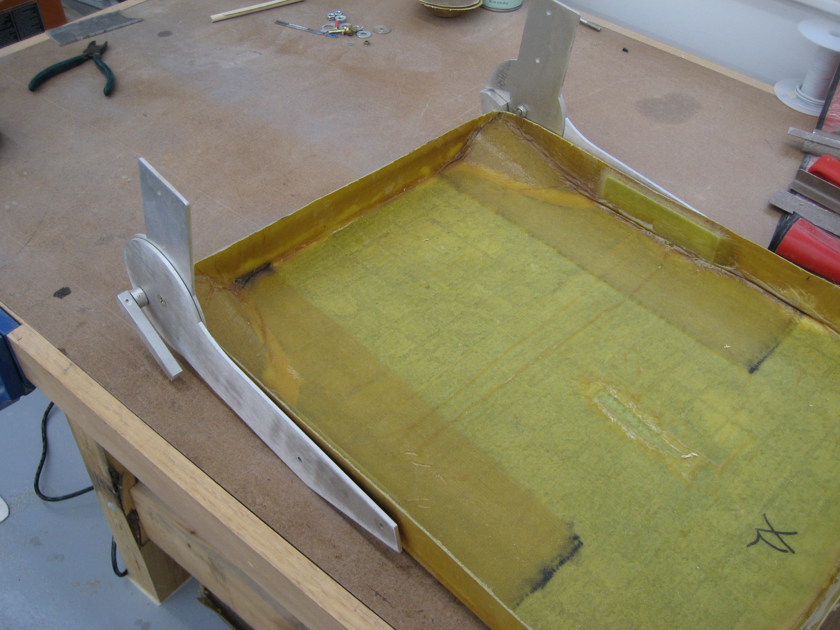
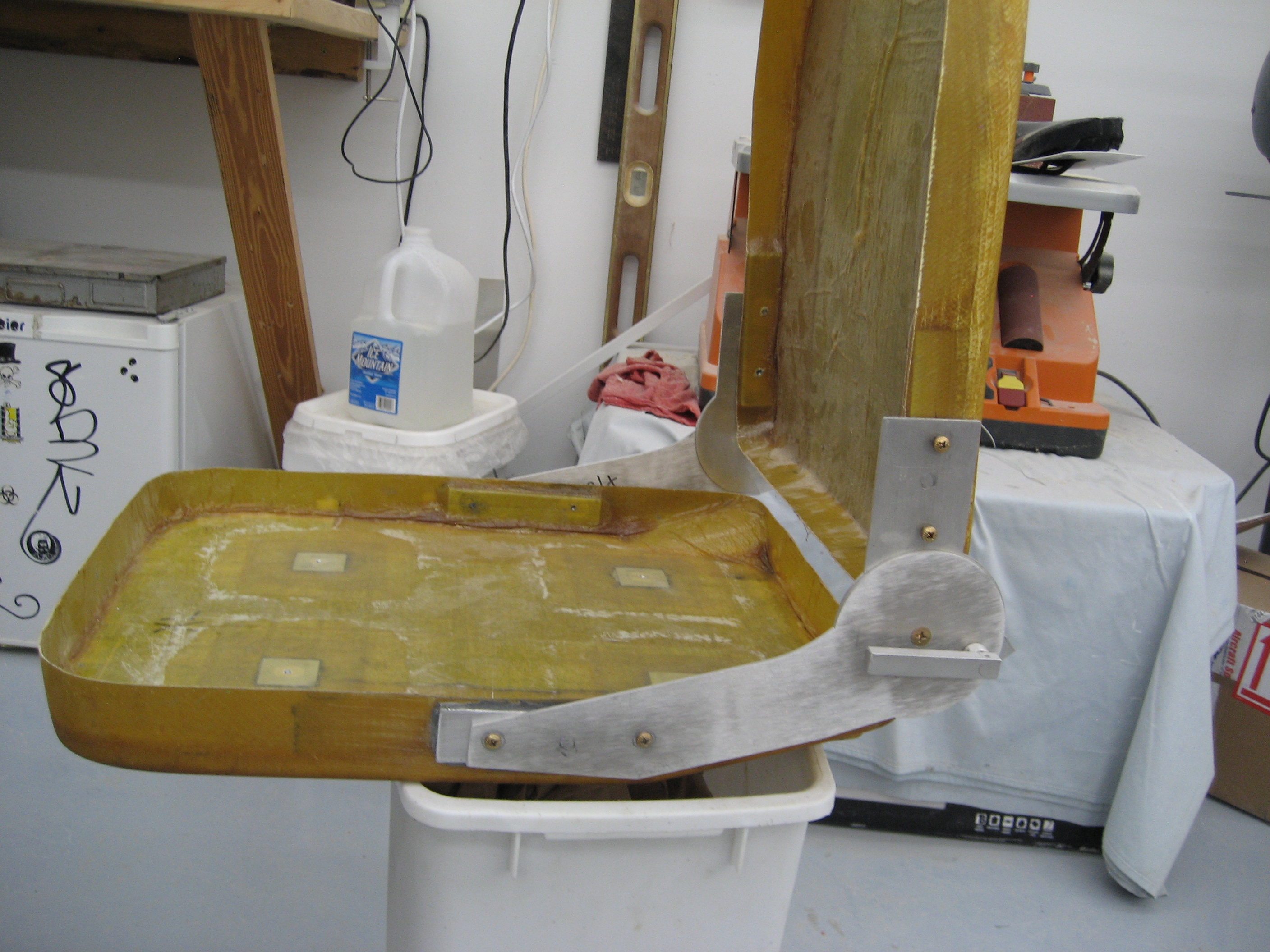
 Here’s the approximate position of the hinge on the seat pan.

2010-04-25 1107 IMG_0528

 But the hinge is wider than the seat pan.

2010-04-25 1108 IMG_0531

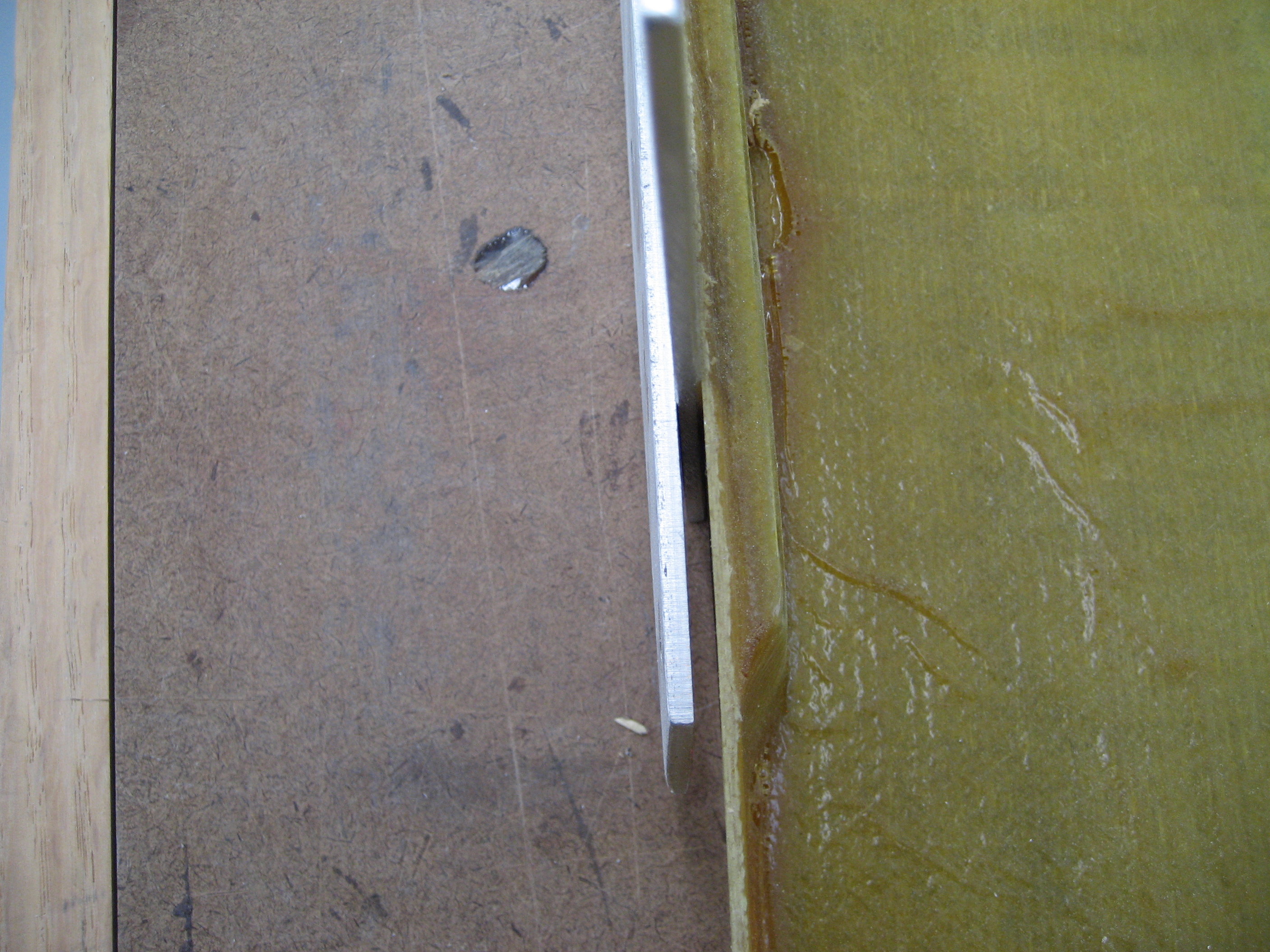
Notice the space between one the hinge arms and the seat pan? If I were to screw it in place the hinge would bind.

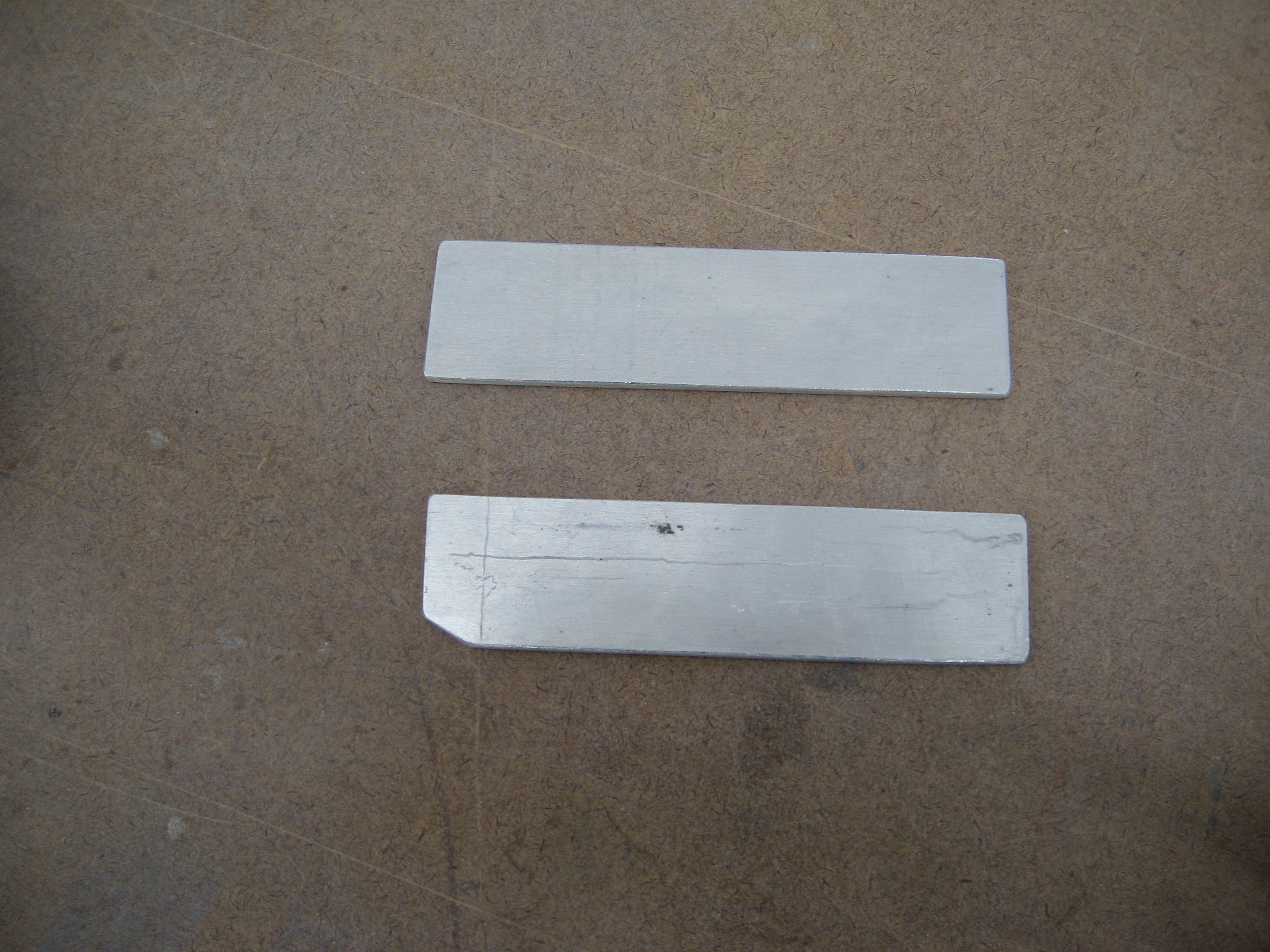
 The gap is exactly 1/8″. And I just happen to have some extra 1/8″ stock laying around so I made a pair of spacers.

2010-04-25 1108 IMG_0532

 I used structural adhesive to bond these to the sides of the seat pan. Then I marked the holes, drilled and tapped them.

2010-06-07 1429 IMG_0595

 The seatbacks have been redesigned to work with the new hinge so no modifications were needed there. It was simply a matter of drilling and tapping the holes. Then I put everything together.

2010-06-07 1346 IMG_0587

Next I had to mount the finished seats to the rails. Four holes are drilled in the seat pan that go through to the rails. Once I located and drilled the holes, then I started thinking about how to attach the pan to the rail. I could use bolts and nuts, but then I wouldn’t be able to remove the pan from the rail once it had foam and upholstery. And I’ve spent enough time fussing on my current plane about stupid engineers who design things without thinking about someone needing to take it apart later.

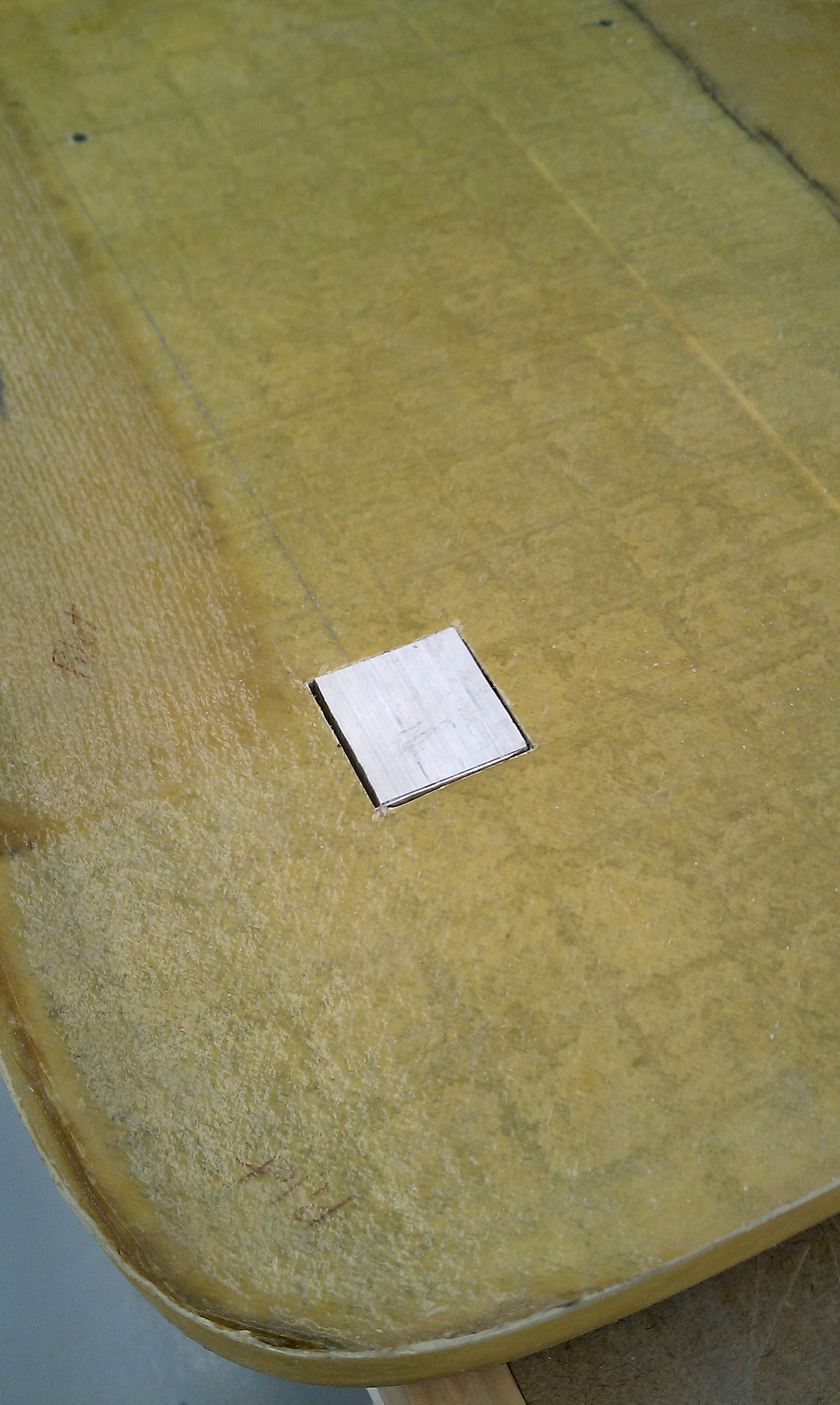
So here’s what I did. I cut some 1/2″ aluminum into 1.5″ squares.

2010-05-02 1120 IMAG0004

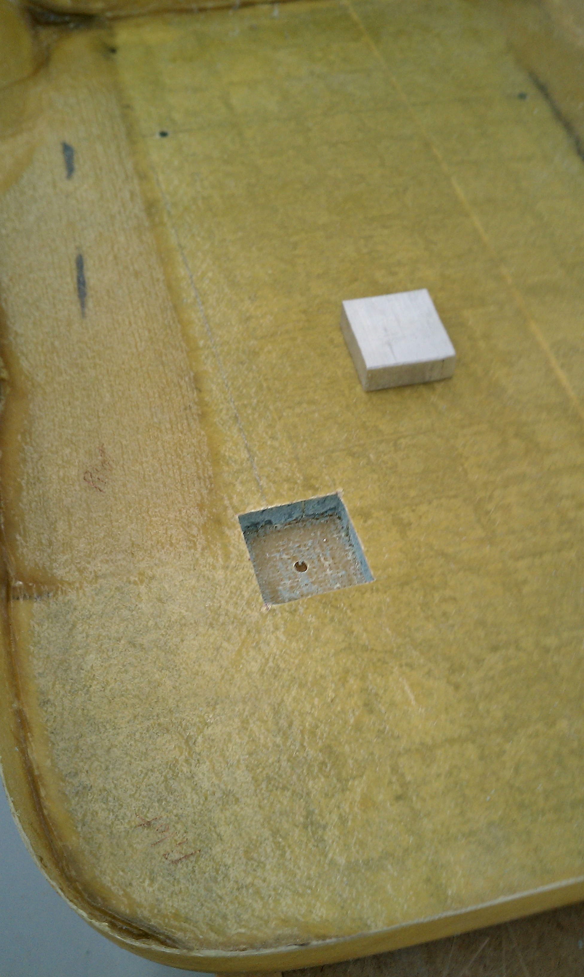
Then I cut an opening in the top (inside) layer and dug out the foam to make a recess.

2010-05-02 1136 IMAG0005

Then I put the aluminum hardpoint in the recess with structural adhesive.

2010-05-02 1136 IMAG0006

And then cover the hardpoints with a layer of BID. Once it cures, drill and tap the holes.

2010-06-07 1342 IMG_0582

Now the seat can be removed from the rails.

6.9 Overhead Fresh Air Plenum Installation

This entry is part 16 of 42 in the series 06 - Fuselage

Now that the overhead beams are installed, the modification to the front of the plenum is done and the lighting for the overhead air plenum is finished, it’s time to install the plenum itself. I had to cut away the side where it meets the overhead beam to the B-pillars. Then I spread structural adhesive and riveted the plenum in place. Most builders probably leave it at that, but I put down a 1 BID layup.

Here’s the plenum after the 1 BID layups had cured.

2010-04-14 0903 IMG_0415

2010-04-14 0903 IMG_0416

Then it’s finishing time. Most builders cover the A-pillars, B-pillars, beams and plenum with some type of upholstery (leather, vinyl, cloth, etc).  But since I decided to follow Andy Millin’s lead and paint these parts, it was time to get to work. As much work as the plenum was, it was EASY compared to these surfaces! The plenum was on a workbench. The surfaces I was working on how were not so easy to work with.

But eventually it was time to paint.

Here’s the result:

B-pillar and part of the plenum

2010-06-07 1430 IMG_0598

2010-06-07 1347 IMG_0588

Closeup of the plenum with the map light.

2010-06-07 1347 IMG_0590

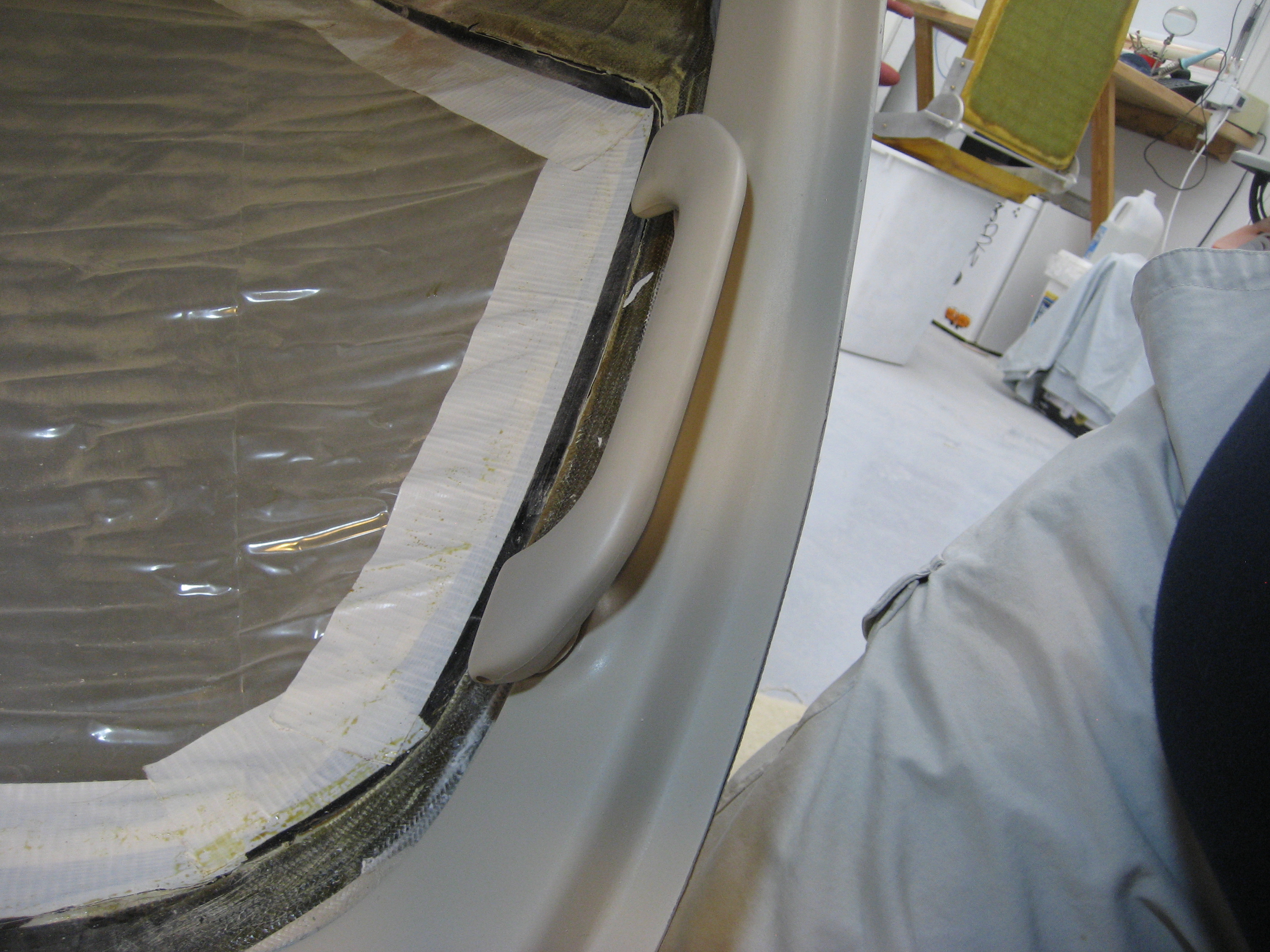
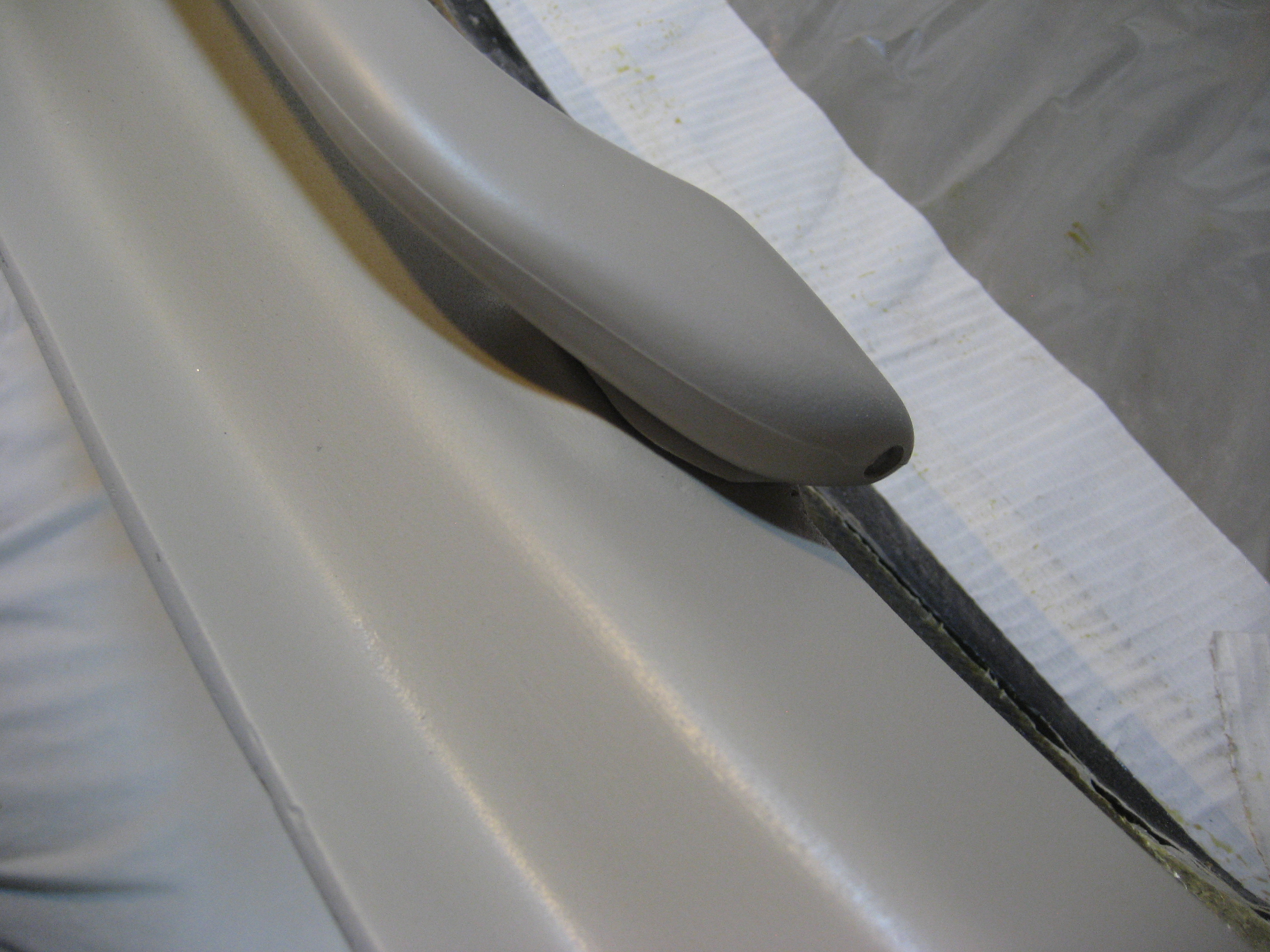
Hand hold on the pilot’s side A-pillar.

2010-06-07 1348 IMG_0592 2010-06-07 1348 IMG_0593

Overhead switch panel (with sample switch).

2010-05-22 1643 IMG_0567

2010-06-07 1348 IMG_0591

6.3.2 Front Seat Rails

This entry is part 38 of 42 in the series 06 - Fuselage

I’ve already installed hardpoints in the seatpans and mounted the seatback. But after talking with the people that will be making the foam cushions (Oregon Aero), I found out that they can make the compressed thickness (how thick the cushion as when you’re sitting on it) to your specifications. They recommended installing the seat to see how much headroom I’ll have first.

This is where having the plane in SC kinda sucks. So next time down, I brought the pilot seat and put some foam blocks on the floor which put the rear of the seat at the height with the same angle that the rails would have. And that’s when I discovered the problem. With an inch and a half of foam between me and the seatpan, my head was jammed into the roof. When I moved the seat so that I could reach the pedals, I couldn’t reach the stick. If I moved the seat forward so I could reach the stick, my knees were elevated so that my thighs were no longer supported by the seat. So I needed to lower the rear (to get headroom) and raise the front (to support my legs).
Here’s the result:
2010-12-22B

Now the problem is that the rails will have to be modified.

Here’s the factory rail.
DSC_0042

Normally people mount these upside down from this picture. That way as you slide the seat forward, it also raises the seat. To gain more headroom, I removed the bottom straps and replaced the top straps with a pair that are taller in the front.

Here it is after a ton of thought and modifying.
2010-12-22D

Modified seat rail installed with me at the controls.
2010-12-22C

I’ve sent the pictures and dimensions to Oregon Aero and now I’m waiting to hear back.

6.2.3 Front Seats

This entry is part 6 of 42 in the series 06 - Fuselage

I received the foam cushions from Oregon Aero for the front seats. You’ll remember last year that we had to modify the pilot seat to accommodate my larger-than-average build (height, not weight, mind you). Once I put the foam on the seat bottom and seat back I discovered 3 problems.

  1. I didn’t think about the height of the seat back. In this picture from last year notice where the top of the seat back is in relation to my neck. Can you say “neck injury”? I didn’t notice this before because I didn’t have any foam in the seat back at the time.
  2. When I had them build the cushions I specified to keep the bottom foam as thin as possible (so I would have adequate headroom). It didn’t occur to me that the seat back cushion thickness would be a problem so I had them use the normal thickness. But because the seat bottom is angled so much, every inch of seat back cushion thickness moves me forward (and up). So I don’t have enough headroom again.
  3. Because of the thicker seat back cushion moving me forward on the seat bottom, my thighs are not supported very well.

Fixing 2 and 3 are easy. I just tell the folks at Oregon Aero to make my seat back cushion like my seat bottom cushion… as thin as possible. That’ll give me headroom and thigh support. But fixing 1 isn’t going to be easy. I thought about an adjustable headrest (like are found in most cars). But then I discovered that the seat back has a “curve” to it. Around the shoulders, it curves to the front so that the back of your head is supported. But with me, the curve started around mid-back.

So I made the decision to modify the seat back to accommodate me. (I should have done the seat bottom too. But I can do that later).

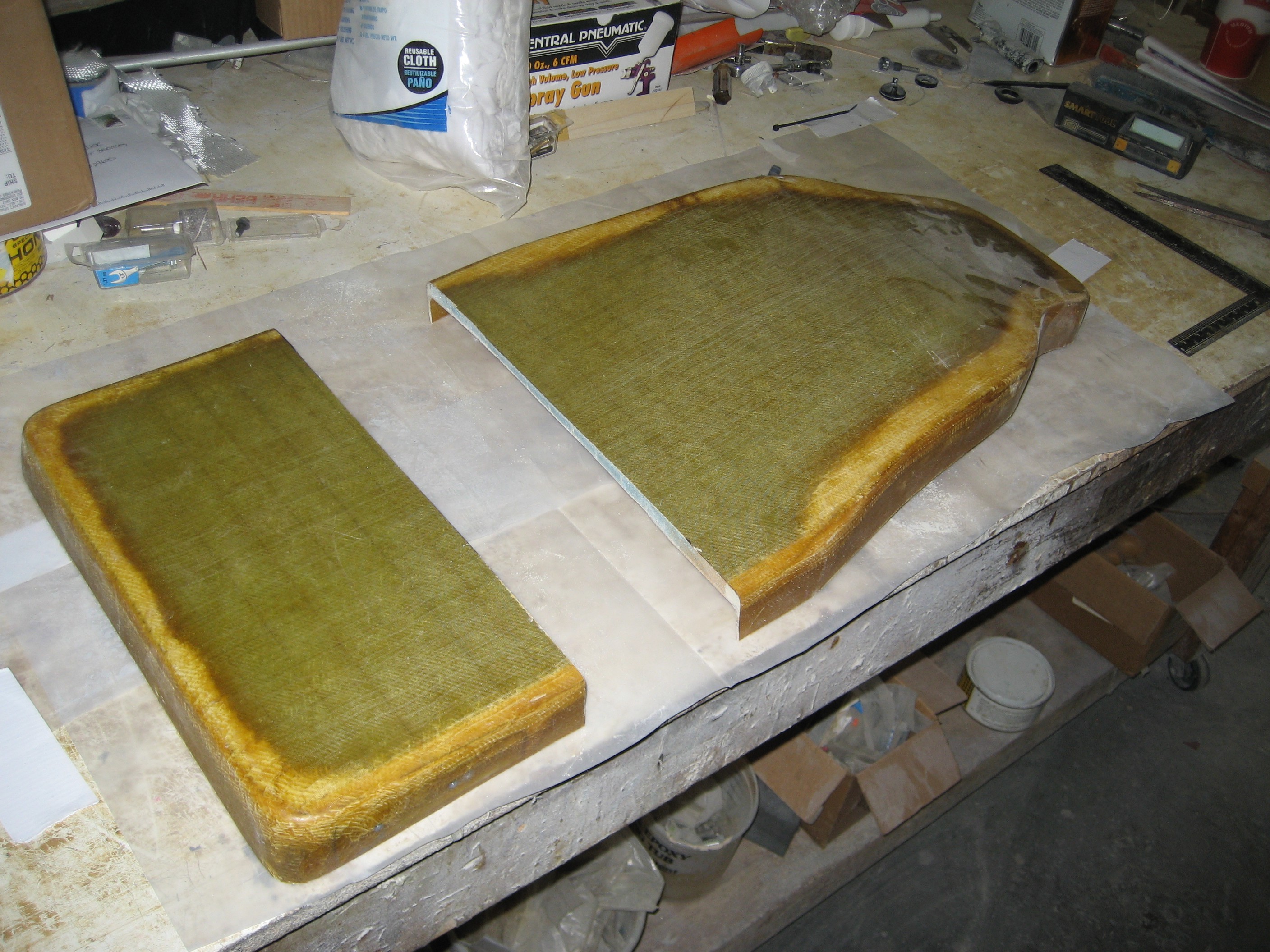
Here’s the stock seatback.

And after the “cut”.

Wood sticks are glued in place to hold the two pieces the correct distance apart and keep them aligned.

A section of 1/4″ foam is placed between the two pieces and tooling wax is attached to the sides.

Then the foam is covered with a micro-slurry and the inside (front) of the seat back is covered with 3 layers of BID and 1 layer of Triax. Once dry, the seat back is flipped over and the same is done to the outside (back). I then mounted the seat in the plane with the seat bottom cushion and a piece of 1/2″ scrap foam in the back.

Here’s the result.

I sent the modified seat back to Oregon Aero so they could build up a taller and thinner cushion.

6.5.2 – Rudder Pedals

This entry is part 1 of 42 in the series 06 - Fuselage

In the middle of all the sanding, pinhole patrol and final prep, I had to work on the “human factors”. After I got my seat geometry figured out and Oregon Aero modified the foam. I wanted to verify that I could fit inside the cabin and reach everything. So brought the seat down with me along with the foam and mounted it in the plane… And it still wasn’t right. It took me a while to determine what was wrong. I could reach the stick and instrument panel but I literally had to reach. If I moved the seat forward, the stick and panel were within reach. But then my knees were sticking up too high. I guess that I have long legs.

I could move the instrument panel back but that wouldn’t help reaching the control stick. I could move that back as well but then I approached it from a different angle. What’s keeping me so far back? Obviously the length of my legs, but what else?

Rudder pedals.

If the rudders pedals were located a bit forward, then I would be closer to the panel and stick. I tried tweaking the adjustments on the rudder pedals but I couldn’t move them far enough forward. So I decided to modify them.

Here’s a (right) side view of one of the rudder pedals.

On the right is where you would put your foot. The white triangular piece is where the pedal assembly mounts. It’s allowed to pivot up and down to activate the brakes. The hole to the right of the mount is where the brake master cylinder attaches. What I did was to drill a new set of holes 1.5″ forward (right in this picture). This results in the pedal being 1.5″ aft of it’s original position. Now with the seat adjusted so that my feet are on the pedals, the stick is at my right hand and the instrument panel is easily within reach. It could be better. But for now, it’ll do. Here’s the “after” picture.