6.3.1 Assemble Rudder Pedals

This entry is part 7 of 42 in the series 06 - Fuselage

While I had already assembled the rudder pedals before, I did modify the pilot side pedals to add legroom. And the components aren’t all assembled with locking nuts. So now it’s time for the final assembly.

While I was getting ready to finish the rudder pedals, Malcolm (ever the perfectionist) pointed out something. This is the top of the master cylinder for the co-pilot side, right rudder pedal. It is attached with a long bolt and (right to left) a locking nut, washer, top of master cylinder, three washers and the rudder pedal arm.

This is how the manual says how to do it. So it’s right. Right?

Well that big gap at the top? Not… optimal. And those THREE washers between the arm and master cylinder? A flat surface (washer) up against a curved surface? Again, not optimal.

So here’s the solution:

Custom made spacers that will prevent any binds and keep the ends of the master cylinder from being pinched.

6.3.1 Brake Lines

This entry is part 8 of 42 in the series 06 - Fuselage

Now that the oil lines are in the duct, the brake lines can be run. since there’s not much in the duct, these can be run just by sticking them in the duct. I started at the back with the small hole drilled in the duct between the firewall and the gear bulkhead. A little coaxing and I had the left and right brake lines coming out the forward hole in the duct.

Before the brake ends of the tubing is pushed down the nylaflo that was bonded to the gear leg, I put the lines through a grommet.

Here is the left brake line coming out of the duct and then down to the brake at the bottom of the gear leg.

Both brake lines.

The brake lines coming out the duct by the brake pedals.

6.3.1 Brake lines

This entry is part 9 of 42 in the series 06 - Fuselage

The brake lines were already run from the wheels to the forward cabin. Since it’s just more plumbing, now it’s time to terminate the lines.

Malcolm likes to reverse the elbow and bleeder valve on the calipers. It makes for a cleaner installation.

Front view of the pilot side main gear.

Inside view of the pilot side main gear.

The forward end of the brake lines are connected to the brake pedals. Here are the pilot side pedals.

6.3.1 Brake Lines

This entry is part 10 of 42 in the series 06 - Fuselage

The reservoir for the brake fluid is mounted in the nose. The goal is to find a location that allows access when the canard is installed. Then once it’s in, the two remaining lines from the toe brakes can be run to the reservoir.

This is the reservoir (on the left) with the gear retract hydraulic pump (on the right).

6A.3.1 Toe Brakes

This entry is part 11 of 42 in the series 06 - Fuselage

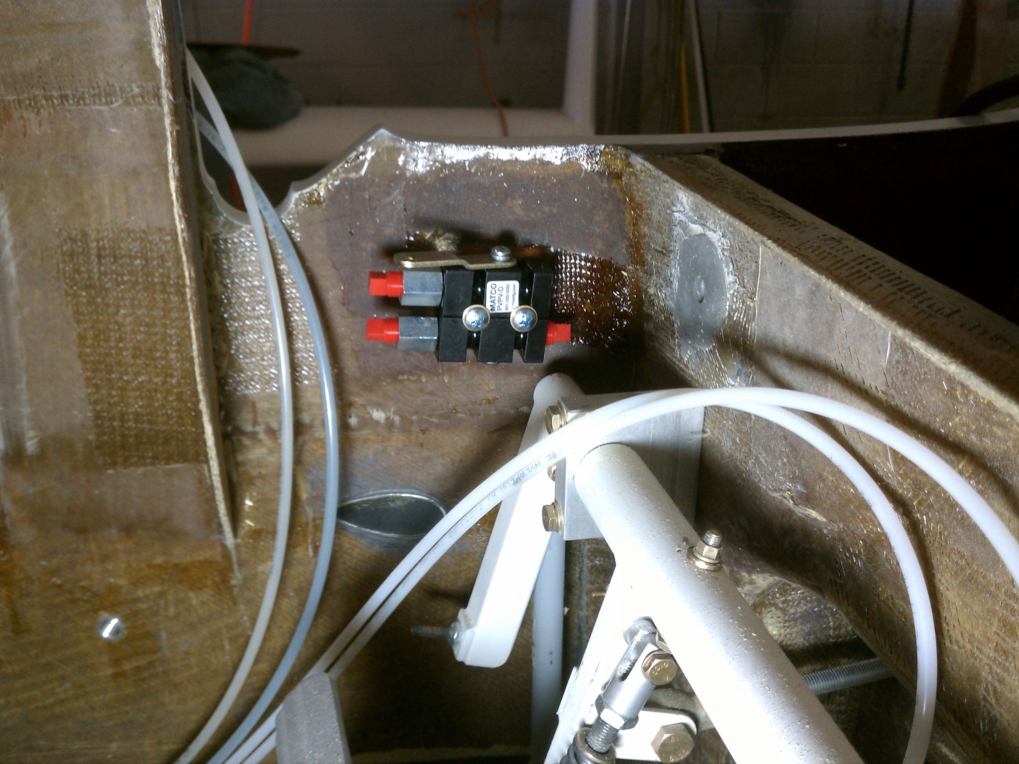
After running the brake lines, I remembered that I forgot the parking brake! It’s a little two piece valve that locks the fluid in the brake lines. First I had to determine where to mount the valve(s) and then make a pad. Then I just needed two screws to hold it in place.

When the lever (top) is towards the back, the brakes are locked. When it’s forward, the brake pedal are active. I couldn’t connect the brake lines yet because I don’t have 3/16″ elbows. But they’re on order.

I’m going to activate the valve by means of the rigid link from the valve to a simple lever mounted on the bottom edge of the instrument panel.

6A.3.1 Parking Brake

This entry is part 12 of 42 in the series 06 - Fuselage

Sometimes you need to keep the plane from rolling when stopped for a short period of time. Waiting for an IFR clearance, stopped on an uneven surface, etc.

The Cessna has this MacGuyver mechanism with cables that go to the brake pedals and a pull lever that looks like it came out of a ’66 Ford Fairlane.

So this is how I’m going to have a parking brake. A dual cylinder valve goes in between the brake pedals and the calipers. The brakes are activated and while holding the pedals down, the valve is closed which keeps the brake line pressurized.

Here’s the valve on the inside of the left side next to the rudder/brake pedals.

Then the brake lines are cut and connected to the valve assembly.

The next task is to fabricate the linkage to the valve which will connect to a level at the bottom of the instrument panel.


6.6.2 – Install Landing Gear Selector

This entry is part 13 of 42 in the series 06 - Fuselage

(Note: as I’m writing this, I’m watching updates from the Mars Curiosity Rover landing)

For the landing gear electrical and control, I purchased the control unit and selector from Wayne Lanza at Composite Designs. This is one of those decisions where I made the call to buy something rather than design it and build it myself. Wayne components are in a LOT of Velocities and the quality of the product is excellent.

I installed the control unit in the nose a few months back and have just been holding the selector in my hand when operating the landing gear. I have, up until now, held off on any decisions regarding instrumentation. Other than a glass panel from Grand Rapids Technology. I decided on GRT because they cater to the experimental aircraft market, they have an excellent reputation for customer server and they are always innovating. Which is why I have held off on a decision. Since I have reached a point where I have to know specifics about the panel layout, I have made the decision to go with their latest, greatest system. The HRx with the 10.4″ screen. This provides all flight and engine information on a single screen along with synthetic vision (the ground is displayed as it actually appears), HITS (Highway In The Sky), weather, remote radios, remote transponder and a whole bunch of other features. I’ll have a separate write-up on the selection process later. I haven’t decided whether to go with two 10.4″ screens or a single screen with a 7″ android tablet as the backup. But for now, I have enough to proceed.

When I was at Oshkosh, Carlos gave me a couple full-size paper representations of the screen. So the first step is to position the primary screen. I started by locating the center (left-right) of the pilots position. From this I extended it to the instrument panel and drew a vertical line. This tells me the point that is directly in front of the pilot.

Then I marked the center of the display and aligned it with the vertical line and taped it to the panel.

Then I cut a piece of cardboard to the size of the landing gear selector and thought about where I wanted it to be.This is the part of building that can be really NICE! Think about… your car. And how the location of the radio bugs you. Well, there’s not a whole lot you can do about that. But I can put things like the gear selector ANYWHERE  I want.

But with great power comes great responsibility. 😉

So here’s something that must be considered: Where you’re landing, sometimes… you can’t. Another plane pulled out onto the runway, a deer just ran across the runway, or maybe you did a bad job in the approach and now you need to go around. The standard procedure is to go full power, start the climb and retract the landing gear. Now the stick is in my right hand so I don’t want to let go of that during a go-around. My left was used to firewall the throttle, prop and mixture so that hand is available. Which means raising the landing gear will need to be done with my left hand.

So that means somewhere in the red shaded area.

Of the three engine controls, the throttle (black) is primary. So my hand will be towards the top of the engine control quadrant. Moving my hand down and to the right to raise the gear is not optimal. So I decided to put the selector above the throttle.

I marked the location and removed the panel. Some people simply mount the selector panel on top of the instrument panel. But I decided to make it flush. So I cut a rectangular hole in the panel and sanded the edges until the front of the selector fit into the hole. Then I took some only fiberglass stock and cut a flange (or backing) that the selector would screw into. I used structural adhesive to attach that to the back of the instrument panel.

The selector is far enough to the left that the instrument panel mounting flange is behind the selector. But this isn’t really a problem. I just won’t make the flange all the way around the opening.

Once the flange (and panel mounting flange) was trimmed, I put everything back together and drilled the four holes for the screws that hold the selector in place. I could have used regular nuts on the back but that would require holding them when tightening the screws. So I decided to use nutplates.

The nutplates are held in position with rivets. The kit comes with pop-rivets… which I detest. I think they’re amateurish. I prefer solid rivets. Any job worth doing…  🙂

But in this case, my rivet squeezer wouldn’t fit for two of the rivets. So I had to fall back on pop-rivets. It’s not structural, so I can live with it.

Here’s the opening in the panel with the partial flange.

Looking at it from the back.

A regular nutplate wouldn’t work in the lower-left corner (which is on the instrument panel flange). I would need a one-arm nutplate… which I don’t have. Since this isn’t structural, I decided to cut one arm off a regular nutplate and forge ahead.

Then I put it all back together.


6.2.2 Safety Harness Hardpoints

This entry is part 14 of 42 in the series 06 - Fuselage

So far, the only safety harness hardpoints that I’ve installed are in the overhead beam for the front seat shoulder harness. I held off on the lap belt hardpoints until I had the harnesses so I could more accurately determine their location.

Well, the harnesses are in. I’m going with a 3/4-point harness in the front (3 attach points but 4 connections at the buckle) with an inertia reel for the shoulder harnesses.  The back will be the standard 3-point with a diagonal shoulder harness (just like in your car).

Here’s the front seat shoulder harness with inertia reel installed.

2014-01-21 IMG_20140121_174905_215

I decided to embed the outboard lap belt hardpoint in the sill just in front of the B-pillar.

This the sill cutout

2014-02-04 IMG_20140204_160729346_HDRa

Since the sill is about 3/4″ thick, I decided to use 3/4″ 2×2 aluminum for the hardpoint.

2014-02-04 IMG_20140204_161509115a2014-02-04 IMG_20140204_164925441a2014-02-04 IMG_20140204_161520978a

Bonded in position with structural adhesive.

2014-02-05 IMG_20140205_100148178a

And covered with two layers of Triax (to bring it flush with the sill and 3 layers of BID.

2014-02-06 IMG_20140206_090407693a

Once it cures, I’ll drill a hole through the BID/Triax.


6.3.2 Seating modifications

This entry is part 39 of 42 in the series 06 - Fuselage

In preparation to doing the weight and balance, I need to get the seats in. The back seats I just put in the back. But I bolted down the front seats. That’s when I noticed something… With the co-pilot seat installed, it’s really difficult getting in and out of the back.  It’s doable, but not easy.

I think it’s because I mounted the seat pretty far aft on the bracket to give Ann some legroom (that girl has some long legs!).

So now the question is: How do I get that seat to move farther forward? Seemed easy to me.  Fit some seat rails that have more travel. The current ones have only about 6″ of front to rear travel.

I Googled, called, emailed every vendor I could find that makes seat rails. Zilch, nada, zip. Every single one that I found will only move about 7″ max.  I found this surprising since about every car I’ve driven for the past 20 years has seats that can move at least 12″.

At this point, I can only come up with two possible options.

1) Hit the auto salvage yards and see if I can find a low profile seat rail that will work.

2) Get a second seat rail and mount it between the seat and the bracket. That way the whole assembly can be moved forward and then the seat itself can be moved forward another 7″.

The good news is that it doesn’t have to be done right away since I’m the only one that will be in the plane for the first 25 hours and after that, there probably won’t be anyone in the back seats for a while.

6.2.2 Safety Harness Replacement

This entry is part 40 of 42 in the series 06 - Fuselage

One of the challenges/frustrations with building an airplane is that you sometimes have to make decisions about things that you don’t have all the information on.

With the safety harness, I deviated from plans in that I wanted a 4-point harness with inertia reels for the shoulder harness.  I made this decision because one or the first things I did when I got the Cessna 182-RG was to install these. They are great!  First, because the shoulder harness is on an inertia reel, you can lean forward to reach things that would otherwise be out of reach. Second, having two straps (one over each shoulder) provides much better restraint than the auto style one strap over the shoulder, diagonal harness.

So I started talking with Steve Pekrul and Seatbelt Planet and ended up with a really nice harness system for the front.

But in actual use, it’s not that nice. I mounted the retractor reels on the overhead beam behind the front seat. The webbing has to exit the reel at particular angle and everything lined up. But Because the top of the seatbacks are the proper height (they are actually above my head), the harness has to come over the headrest and then down to the shoulders. So it’s rubbing the back of your head the whole time. And because the point where the two shoulder straps meet is so close, the two straps are always rubbing on the side of your neck. I could have created a slot in the back of the seat and fed the strap through. But the seats are already covered. And it would have messed up the geometry of the strap leaving the reel.

So I decided to investigate the harness that Velocity uses. I found out that their 3-point harness is made by Beam’s which is who made mine. Then I got in touch with my friend Bob who has them in his twin to find out what his thoughts where. His report was mostly positive except that he said the inertia reels don’t always lock in turbulence and while it’s not a problem for the shoulder harness, it is for the lap belt. That isn’t a problem with the 4-point since the lap belts are manually adjusted.

Time for most investigating.

I called up Steve at Seatbelt Planet again. He remembered me because I guess he doesn’t get that many people buying safety harnesses for experimental aircraft. 🙂

I explained what I was looking for is a 3-point harness that will reliably lock in turbulence.

It turns out that Seatbelt Planet was started by one of the people that started Beam’s.  And that they produce some of the components that Beam’s uses in their harnesses.

Steve made some suggestions.  Like using a manual lap belt and a retractor for the shoulder.  But that’s a bit of a kludge.  What we ended up settling on was something called the “Tri-Lock” retractor with a 3-point setup.  The Tri-Lock works like this: In normal mode, it uses an ELR (Emergency Locking Retractor) which locks when you pull too fast or if the mechanism senses an upset.  This is done by means of a small ball in the retractor that if it gets displaced the reel locks.  Because of this the retractor has to be mounted perfectly vertical.  It sounds like this will lock pretty reliably.

But the neat part is when you put it in ratchet mode.  When you pull the harness all the way out, it will retract, but not extend. So if you think there’s turbulence ahead, you can lock it down as tight as you want.

The downside is that if you want it back in ELR mode, you have to unbuckle it completely and let it retract all the way to the rest position. But that would only take one second at the most so I guess that once you’re through the turbulence, you can reset it.

Here’s a video that shows how it works.

Beam’s Tri-Lock

The harnesses came in a couple days ago so I’ll start working on getting the new hardpoints in once I’m done with my very first annual.

The other reason for the new harness is that Ann explained that the harness color that I bought didn’t go with the interior color palette that she is using. 😉