9.4.1 Fuel Cap Remediation

This entry is part 16 of 18 in the series 09 - Fuel System

I wasn’t present when the fuel cap installation began. When I saw how they were installed, I wasn’t nuts about them but I wasn’t certain that they were not… optimal and didn’t want to make a stink about it. Besides, I figured it would be a real pain to fix anyway. But after looking at planes at Sun-n-Fun and Oshkosh, I knew something had to be done.

Here’s what the fuel caps look like.

2009-03-29 1748 IMG_8496 2009-03-29 1748 IMG_8495

I wanted a flush installation. I think part of the problem was that these fuel caps aren’t the ones that come from the factory. Those were kind of cheap looking with a fair amount of plastic. So I found a company that makes fuel cell caps for race cars. No plastic, all metal, very high quality.

The first order of business was to cut out the cap. I first cut out just the cap itself. But then I realized that I would need to put a backing plate inside. So I cut the hole into an oval.

2009-08-08 0800 IMG_9129

Here’s the hole with the backing plate.

2009-08-08 0800 IMG_9130

Then I cut a hole into the backing plate and put on a couple coats of Jeffco (fuel resistant epoxy). Once it was dry I mixed up some more Jeffco and added some Cab-o-sil (thickener) and spread it around the edges. Then I put the backing plate inside the fuel tank and pulled it up against the inside of the tank.

Now I had to make a mounting flange. So I clamped the fuel cap collar to a piece of 1/4″ aluminum stock.

   2009-08-08 0802 IMG_9132

Drilled (and tapped) the holes for the collar.

2009-08-08 0810 IMG_9134

Then I marked the center for the BAH (Big Assed Hole).

2009-08-08 0823 IMG_9135

Then I used a hole saw to drill the BAH.

2009-08-08 0903 IMG_9136

Finally I cut out the outside. My 15 year old jig saw really wasn’t up to the task. But the outside cut wasn’t critical.

2009-08-08 0912 IMG_9137

Then using Jeffco with cab-o-sil to thicken it, I secured the flange in place.

The next step was to cover the screw holes with some duct tape. (Here I’ve done all but one) Then fill in any voids with thick Jeffco and cover the whole thing with fiberglass.

 2009-08-08 0800 IMG_9131

Then I cut out the holes, plopped some some thick Jeffco down the screwed down the collar to the mounting flange. Once it cured, I filled and sanded the surrounding area:

2009-08-12 1910 IMG_91392009-08-12 1910 IMG_9140

Much better.

5.5 Strake Extension Cutout

This entry is part 10 of 16 in the series 05 - Doors / Windows

One of the things Ann did at Oshkosh was look at every single Velocity interior she could find. Since she is designing the interior, she needed ideas. Unfortunately, she found some.

Here the scoop. The strake extends forward about halfway into the door. What most people do is make a triangular cutout in the door and use that space as a type of arm rest. My plan was to skip this step. Ann didn’t like that. She and Malcolm both strongly “suggested” that the cutout be made… and it was.

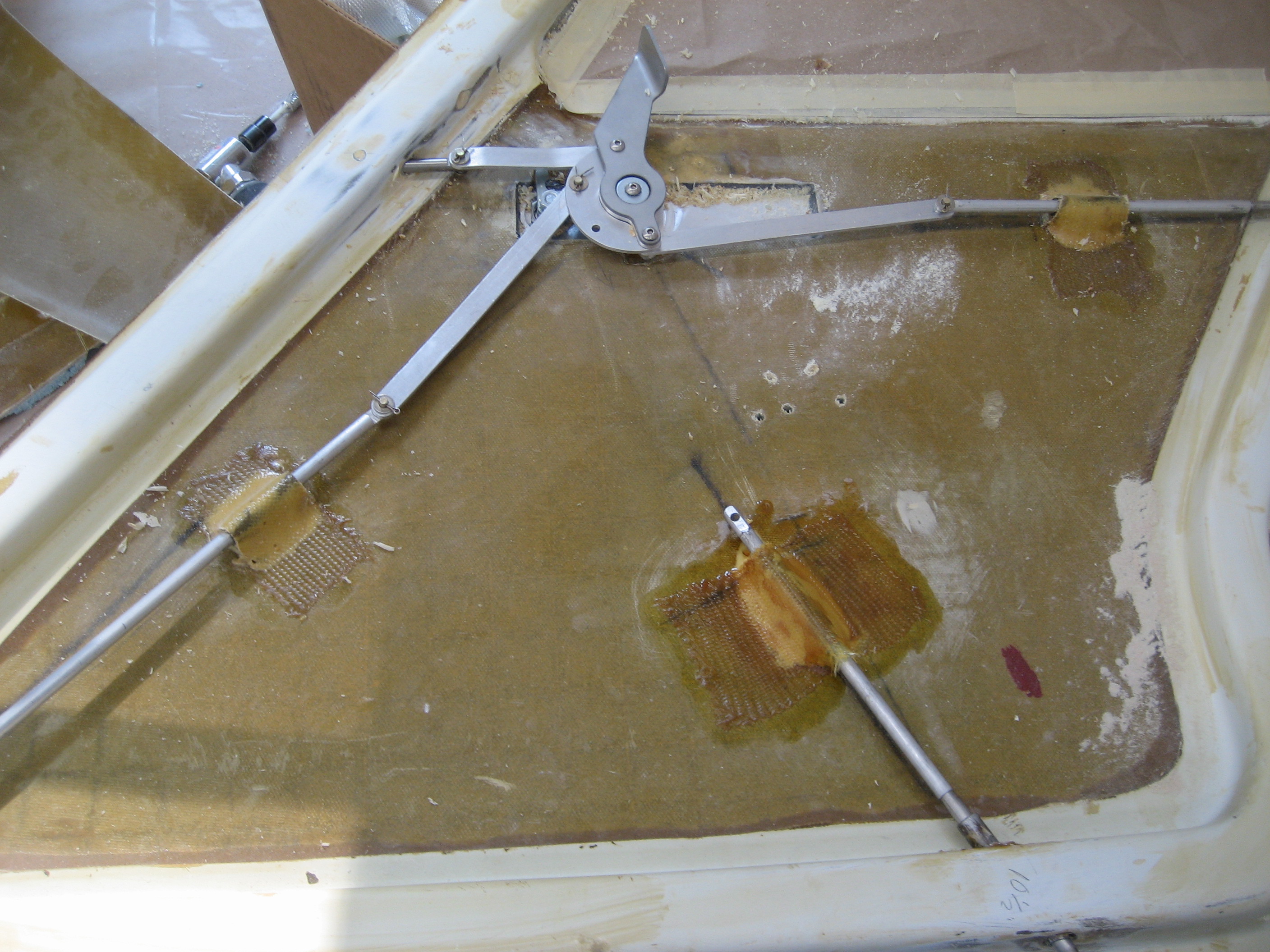
But there’s a catch. When I designed the door linkage, I didn’t think there would be a cutout. If I did, I would have accommodated it. As it was, it required a bit of a workaround.

First I had to remove the lower/rear pin and it’s linkage.

2009-09-01 1900 IMG_9184

Then it had to be relocated forward.

2009-09-02 0727 IMG_9186

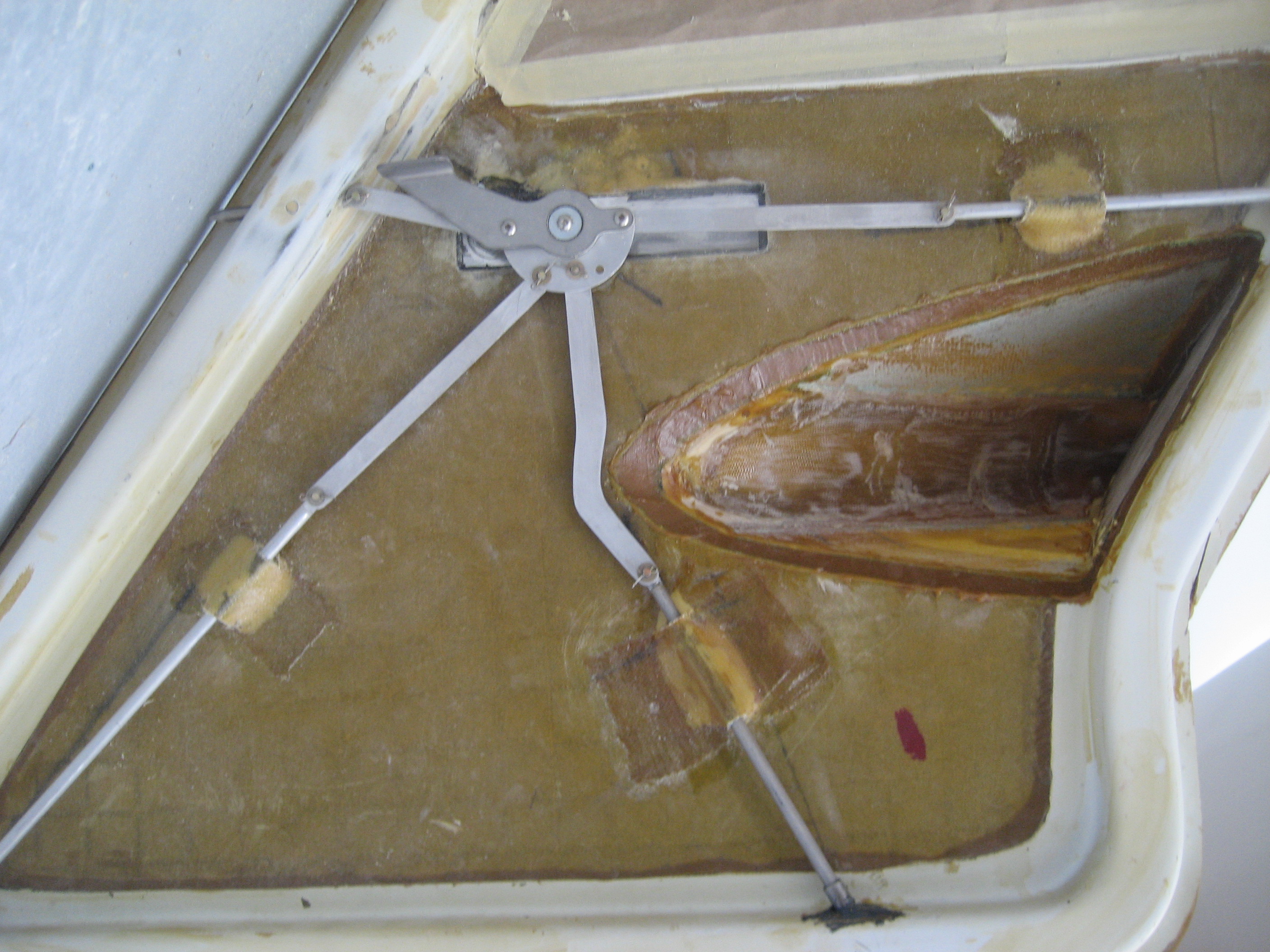
Next I cut out the door panel where the strake extension was. That’s when I noticed that I would need a slight dogleg in that link.

2009-09-04 1747 IMG_9188

2009-09-04 1747 IMG_9189

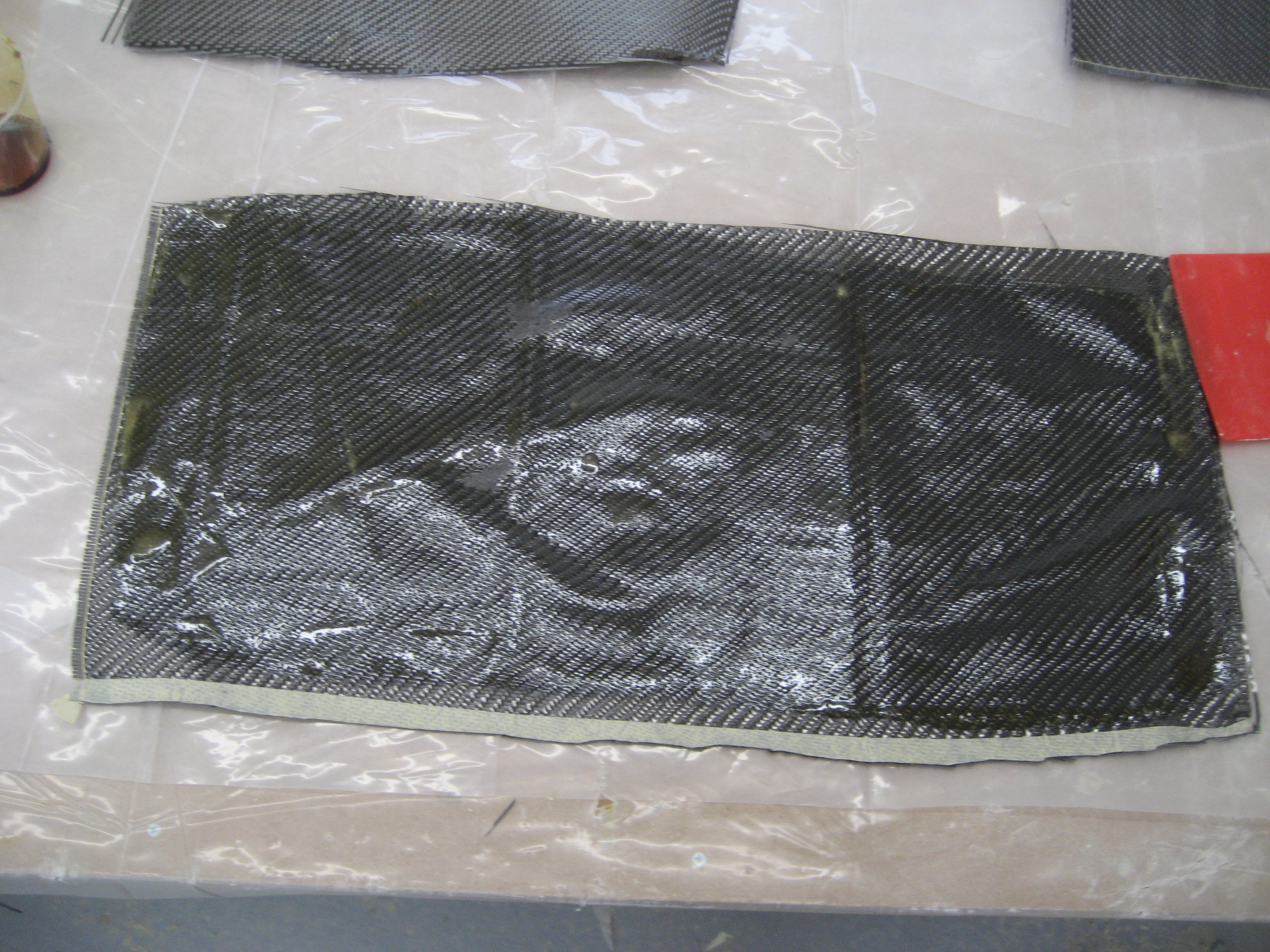
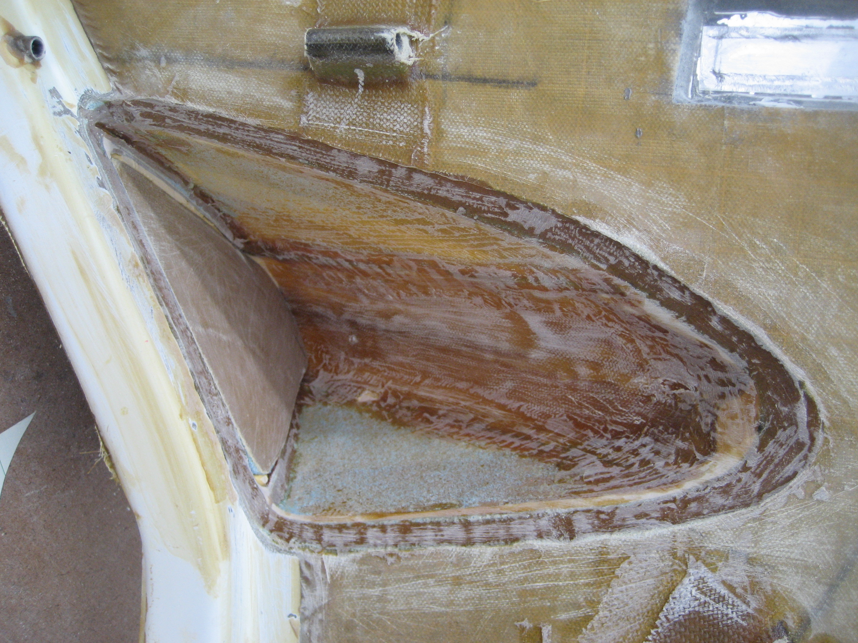
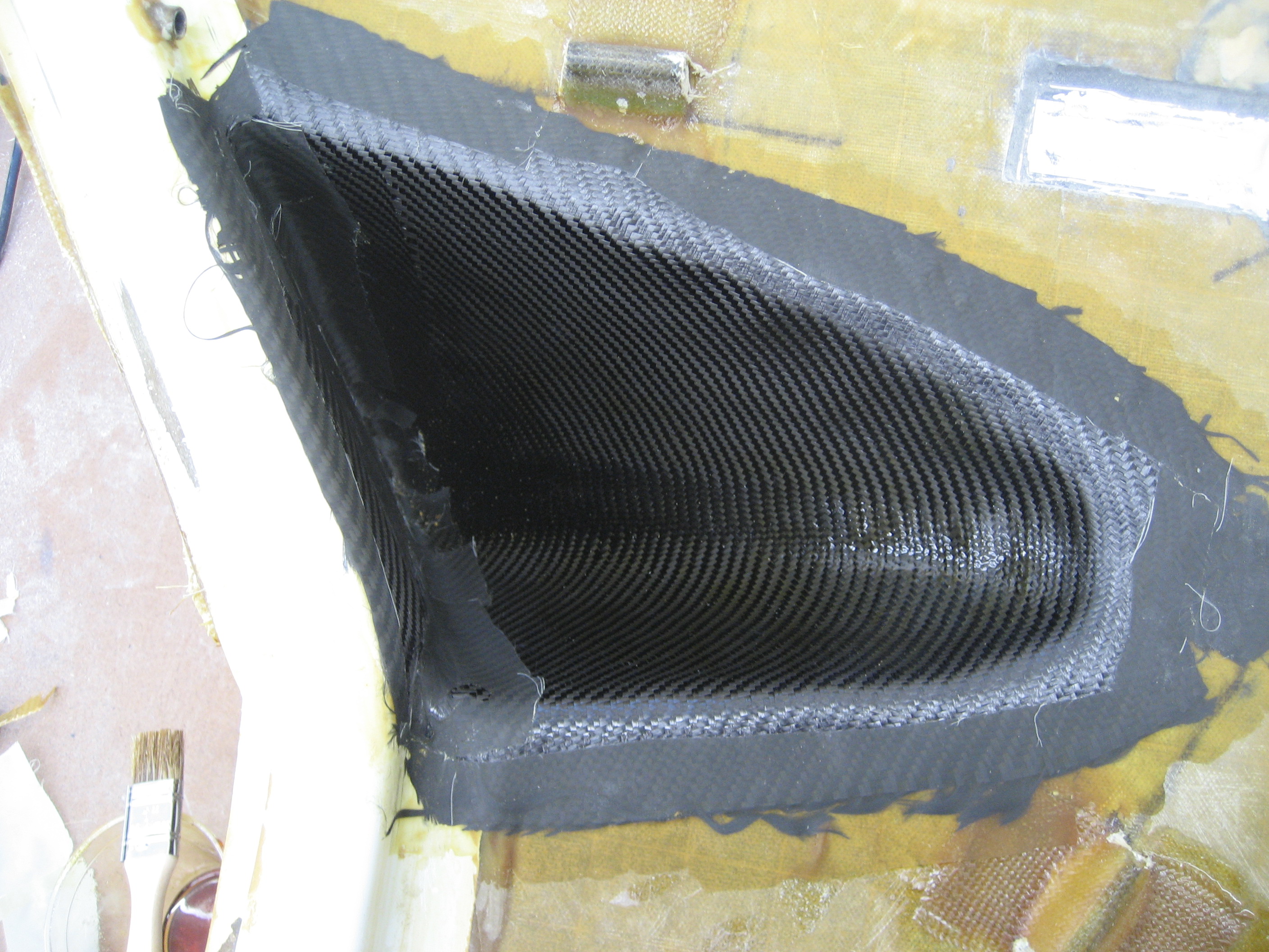
The strake is made of 1/2″ foam with a outer and inner fiberglass skin. That “sandwich” of foam and fiberglass is what gives the structure it’s strength. Now here’s a Hangar 18 special: Remove the inner fiberglass skin and foam. That way you pickup an additional inch of room. But it’s weak with just the outer skin. Carbon Fiber to the rescue. I hadn’t worked with CF before but afterwards, I think it’s easier to work with. If only it weren’t so EXPENSIVE. Here’s two layers of carbon fiber ready to be cut and laid in place.

2009-09-06 1340 IMG_9190 2009-09-06 1340 IMG_9192

Opening before:

2009-09-06 1340 IMG_9193

Opening after:

2009-09-07 0707 IMG_9194

And it’s stronger.

6.9 Overhead Plenum Lights

This entry is part 32 of 42 in the series 06 - Fuselage

Soon, I’ll be installing the overhead fresh air plenum. I’ll need the have the lights fitted before I get to that point. I looked at Oshkosh for some good LED map/courtesy/flood lights. I found a bunch but as is the case with many things aviation, just because it goes in an airplane, you can usually add a zero to the price. What should cost $12 ends up costing $120.

$110 lights
$130 lights

$145 lights

See what I mean? But just like the door linkage…  Something I know about.

Here’s what I did. I found a light for boats. A Perko 12v light.

2009-08-17 1821 IMG_9148

I bought 4 of these at a marine supply store. Now this fixture has a 12volt incandescent light inside (I’m going to have a 28v electrical system). But that didn’t matter because I just wanted it for the plastic.

2009-08-17 1822 IMG_9150

I removed the bulb, mounting hardware and wires.

I purchased a dozen high intensity white and red LEDs at (of all places) superbrightleds.com.

Now I was venturing into uncharted territory. To have circuit boards manufactured would have cost me about $100. I discovered a way to make them myself. I created the layout using a free PCB (Printed Circuit Board) design program I found on the internet.

2009-08-21 1839 IMG_9151

Now here’s a neat trick: If you print the layout on slick, shiny paper, it transfers to the circuit board better. Finally a use for all those clothing catalogs my wife gets in the mail.

2009-08-21 1840 IMG_9152

I picked up a blank copper clad circuit board and Radio Shack.

2009-08-21 1840 IMG_9153

Then I put the paper on the circuit board and using a regular clothes iron, transferred the ink to the card. The paper comes off by soaking the whole thing in water for a couple minutes and then it goes into an etching solution (purchased at Radio Shack) for 20 minutes.

I cut out the individual, circular PCB and epoxied it to the back of the light fixture. Then I drilled the holes for the LEDs, resistors and leads and started soldering.

This first one was a “proof of concept” prototype. I just wanted to make sure the design worked. So I pretty much slapped it together and installed some test points instead of wires.

2009-08-22 1421 IMG_9157

I SAID it was a prototype. It’s not SUPPOSED to look pretty.

2009-08-22 1421 IMG_9158

Red

2009-08-22 1420 IMG_9155

White

2009-08-22 1420 IMG_9156

WooHoo!

One thing I didn’t like was when I soldered the components in the solder would run all the was along the trace. On real PCBs there’s a “solder mask” that contains the solder. Then I discovered that you can create a poor-mans solder mask using glass paint from the hobby store. This is paint that you can use on glass to create a stained glass effect. After painting it on, you bake it in the oven to cure it. After that, you got a solder mask.

Here’s a “production” model.

2009-09-14 1903 IMG_9233

2009-09-14 1904 IMG_9236

Total cost for the for lights: About $50.

00 Flipping the Fuselage

This entry is part 25 of 28 in the series 00 - Prep/Logistics

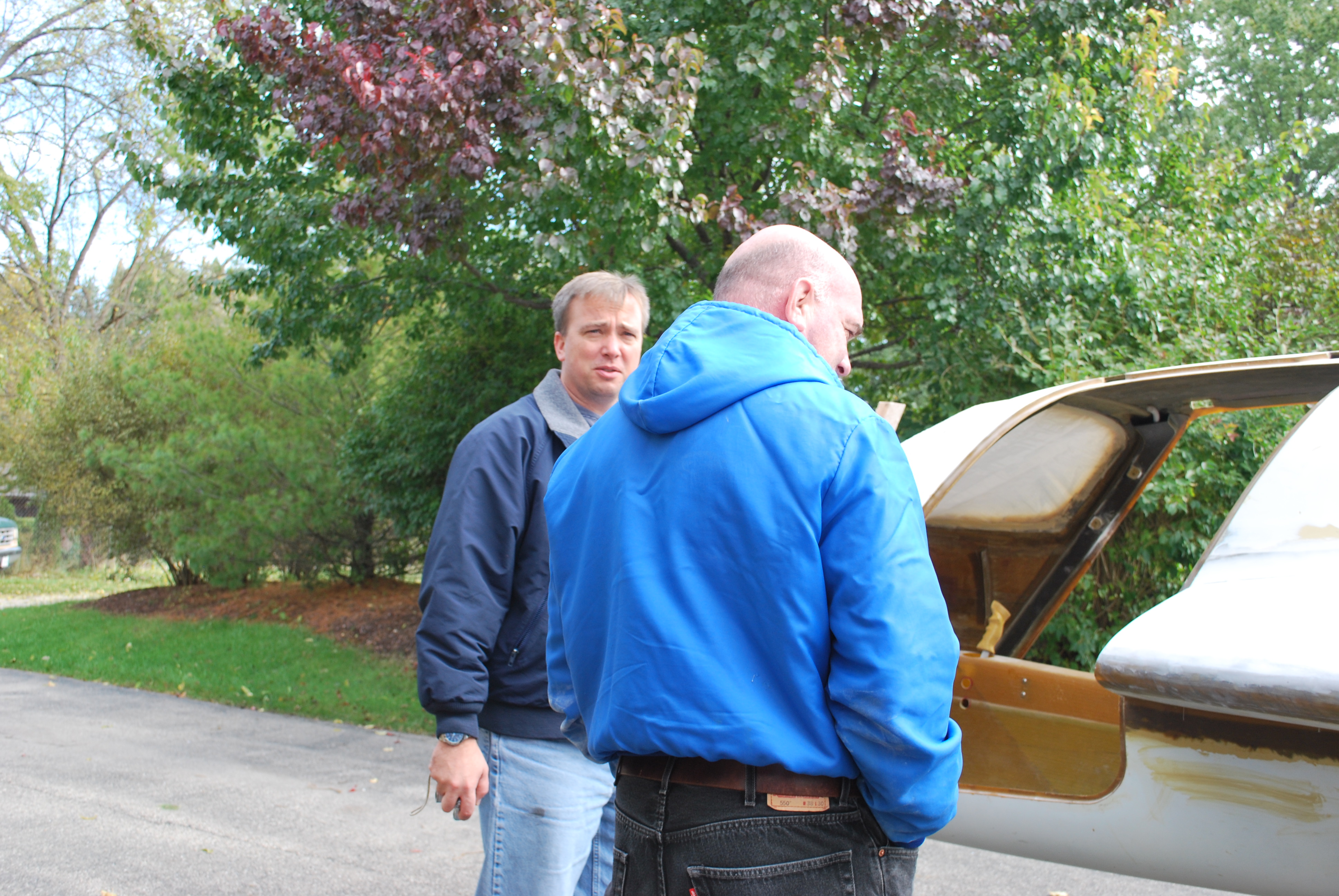
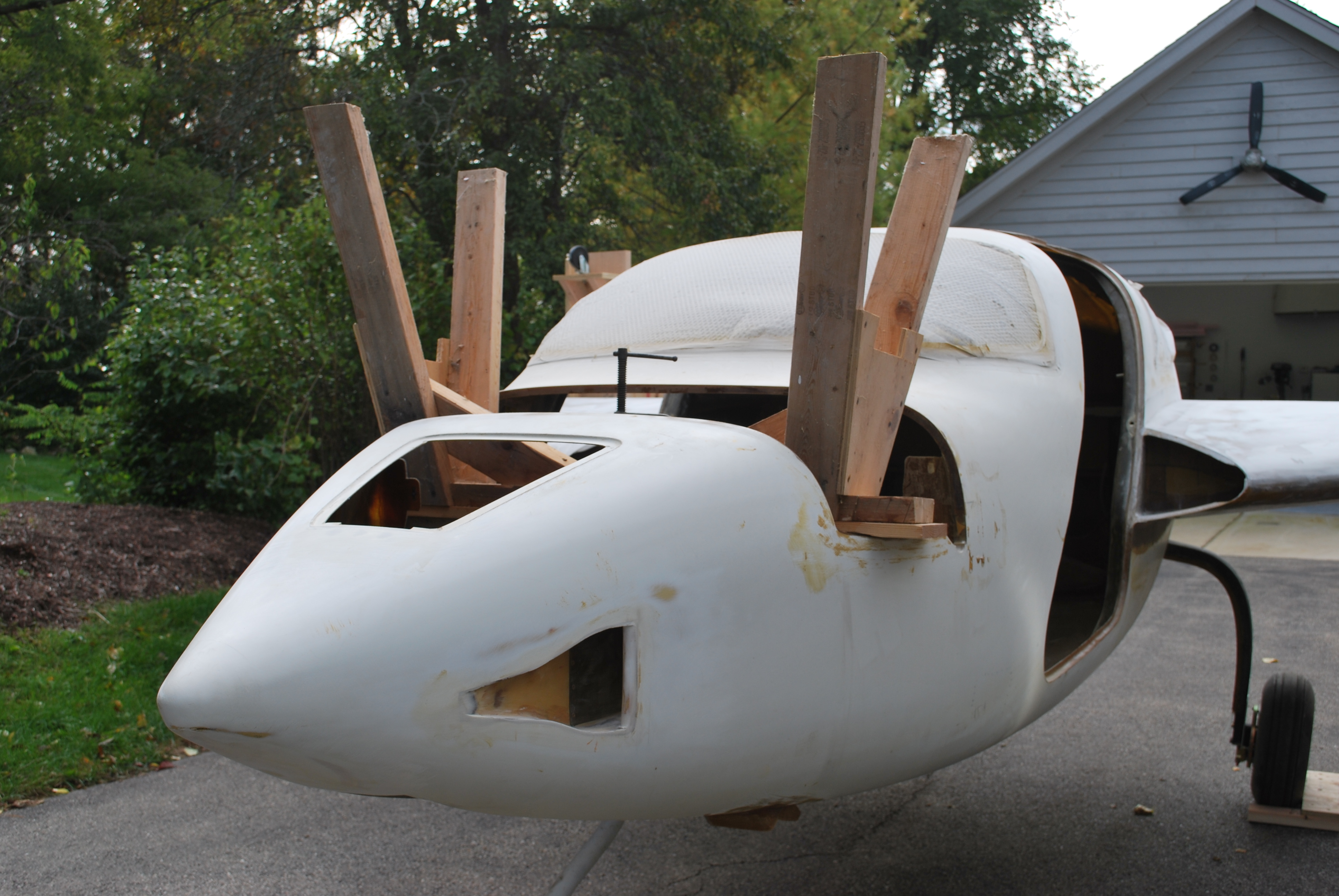
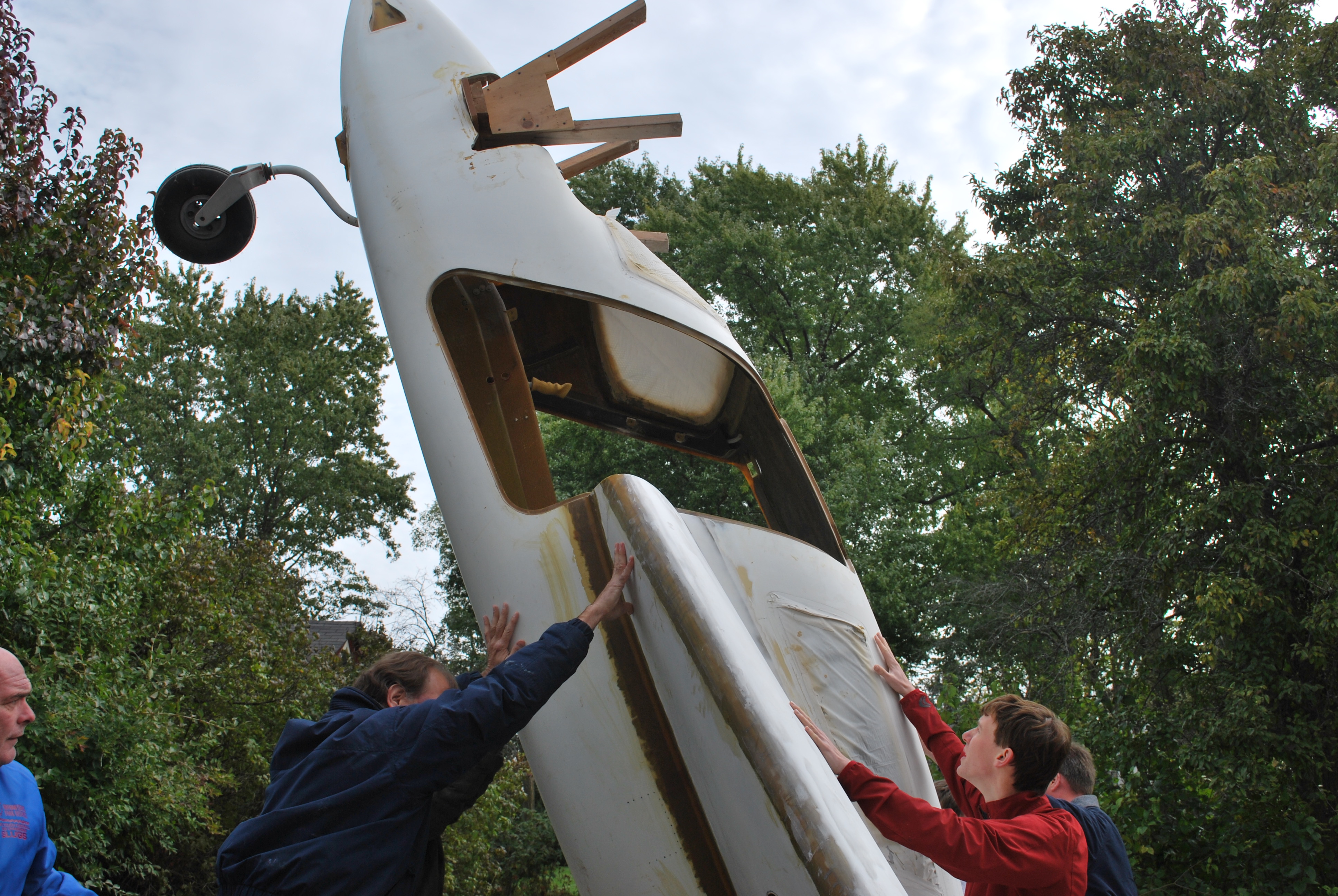
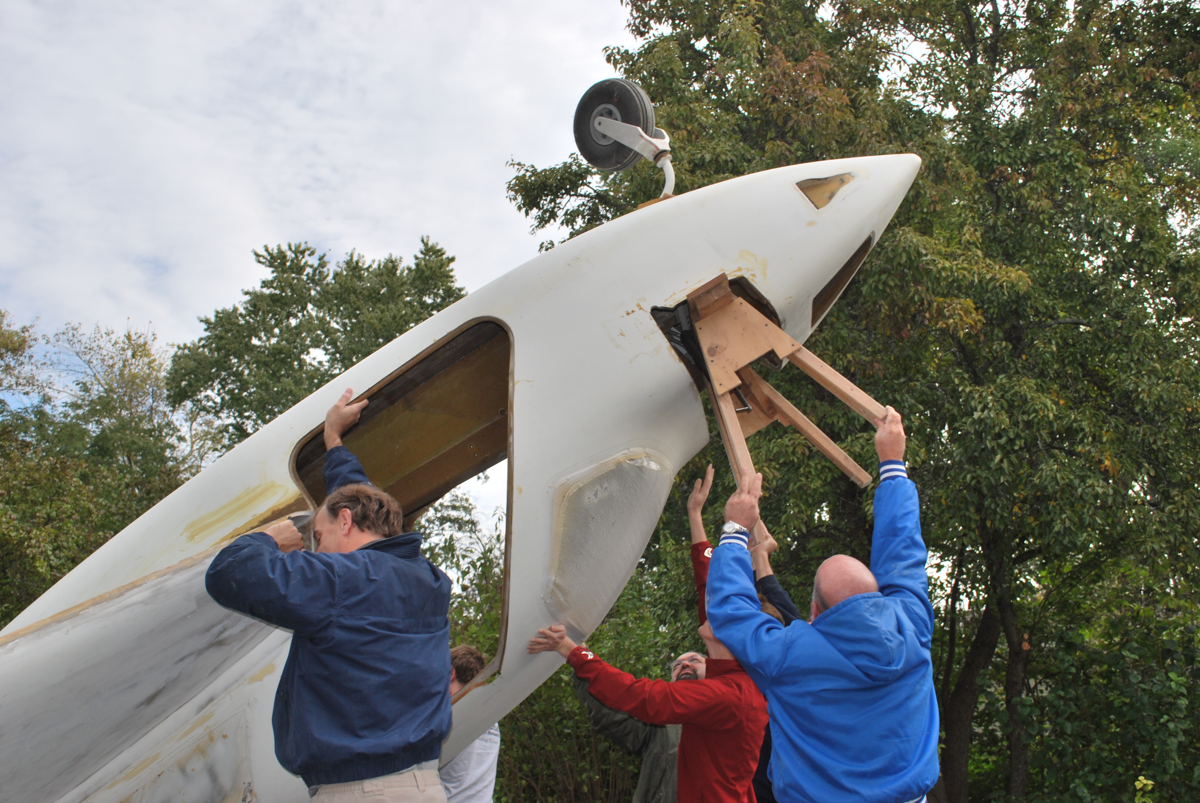
There’s quite a bit of work to perform on the bottom of the fuselage. Mostly finish type work but some mechanical work too. Trying to do this work from underneath is difficult so while the fuselage is still fairly light it’s easier to flip the plane and do it from the top. So I built a set of semi-circular flip jigs and bolted them to the center strake. Then I put out a call for a number of people to help with the manual labor. Here’s Mark (left) and John (right) wondering “how in the hell is this thing going to fly?” before the flip.

2009-10-11 0112 DSC_0337

I clamped a sawhorse to the top (it will soon be underneath) of the canard bulkhead to support the front once it’s flipped.           

2009-10-11 0113 DSC_0339

Ken walking around wondering “how in the hell is this thing going to fly?”

2009-10-11 0120 DSC_0341

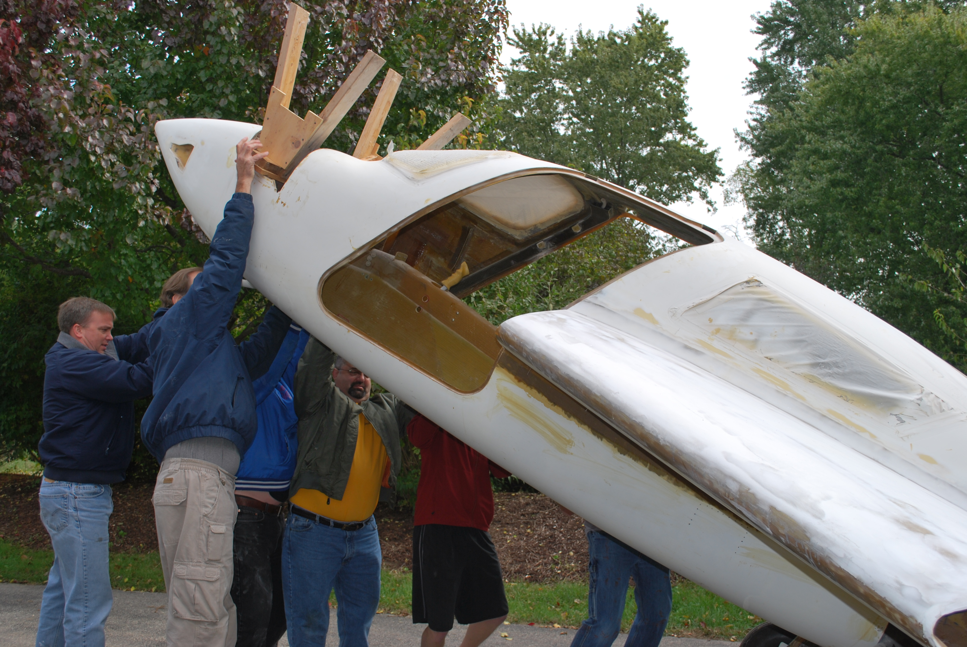
Me, Mark, John, Ken, Steve and Tom staring the lift.

2009-10-11 0121 DSC_0342

Me (left), Steve (right), Mark (behind Steve) almost at the halfway point. John (far left) is looking like he wants to get as far from this operation as possible.

2009-10-11 0121 DSC_0343

Over the top. Everybody else has moved over the other side. I’m just leaning on this side so everybody else can feel a little extra weight.

2009-10-11 0121 DSC_0344

Coming down.

2009-10-11 0121 DSC_0345

Just a little further. In addition to supporting the front, the sawhorse also makes for something to hold onto as John figured out.

2009-10-11 0122 DSC_0346

The eagle has landed! Tom (left, and note the t-shirt on a 40 degree day), Ken (middle) and a happy me (right).

2009-10-11 0122 DSC_0347

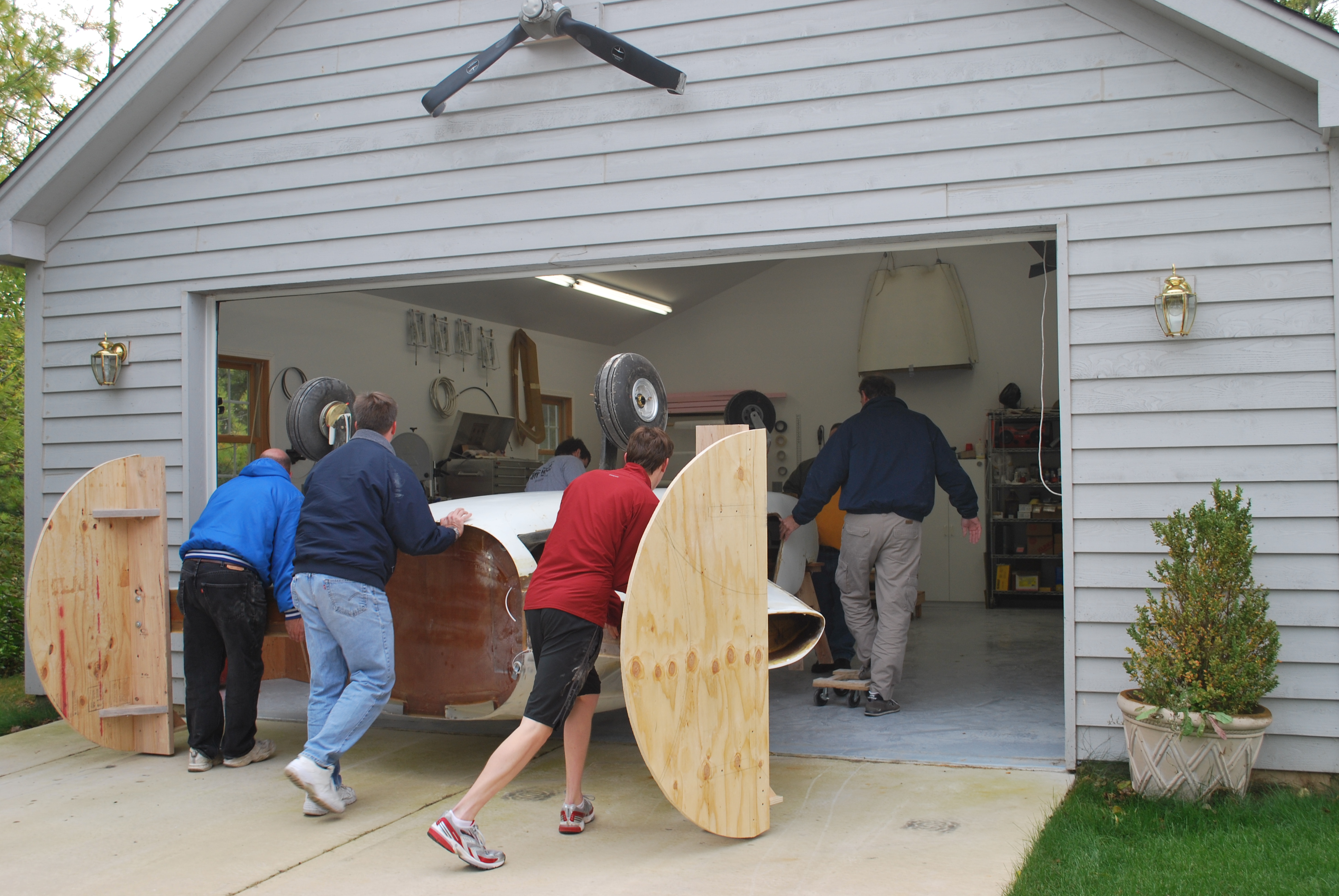
Rolling the turtle back in the shop. John (left), Mark (middle) and Steve (right, and note the shorts on a 40 degree day) pushing.

2009-10-11 0124 DSC_0352

Official event photographer Sarah.

2009-10-11 0130 DSC_0358

7.7.1 Main Gear Leg UpStops

This entry is part 30 of 39 in the series 07 - Landing Gear

Next comes the main gear legs. Here’s the left side main gear leg in the “down and locked” position.
2009-10-11 0622 DSC_0363

And here is the leg in the retracted position
2009-10-21 0812 IMG_9451

The first thing I need to do is define the exact “up” position. So I put a 1/4″ piece of wood between the tire and the wheel well. Then I need to make that position permanent. The channel (or tunnel) that the gear leg sits in is supposed to be just a quarter inch above the leg. I say supposed to because mine is about 2 1/2″ (that will cost me a couple gallons of fuel). So I made a spacer out of leftover stock and glassed it in place. Then I wrapped a couple layers of duct tape on the gear leg, put a UNI/epoxy/cabo fill on top of the spacer and pushed the gear against the wood spacer. Let it set up over night and now I’ve got an “up stop”. I’ll clean this up later.

2009-10-21 0725 IMG_9450

This gets done to both sides.  


7.7.3 Main Gear Doors

This entry is part 31 of 39 in the series 07 - Landing Gear

When the main gear is retracted, the opening (most of it) is covered with a door. This door has to be cut to fit. Here’s the door before cutting. (The pencil line are reference lines for cutting )

2009-10-21 0813 IMG_9453

Here’s the door after cutting. The tongue depressors are glued to the door to keep it flush with the surface.

2009-10-30 0806 IMG_9482

I looked at that bottom opening and thought about a second door to close that off but decided it would too much work for not enough gain. 

Then the back side of the doors have to be strengthened/stiffened. This is done by gluing 1/4″ foam to the inside, beveling the edges and glassing over it with 2 layers of BID.

6.0 Aft Carbon Beam (Remediation)

This entry is part 33 of 42 in the series 06 - Fuselage

The NACA ducts that I installed nearly two years ago need to be reinforced from the inside. So a couple layers of BID around the edges of the NACAs and the fresh air duct.

Now comes the big stuff. I’m not going with the diagonal shoulder belt system that the factory sells (and is found in most cars); a lap belt and a diagonal shoulder harness. Instead, I’m going with a 4-point style with a lap belt and two shoulder harnesses that connect to a center buckle.

The problem here is that with the fast build, the factory puts in the hardpoint for a diagonal shoulder harness (this is the stuff that you don’t think about when you’re starting all of this). So I’m going to have to completely remove the B-pillar/overhead beam.

2009-10-13 2250 DSC_0365

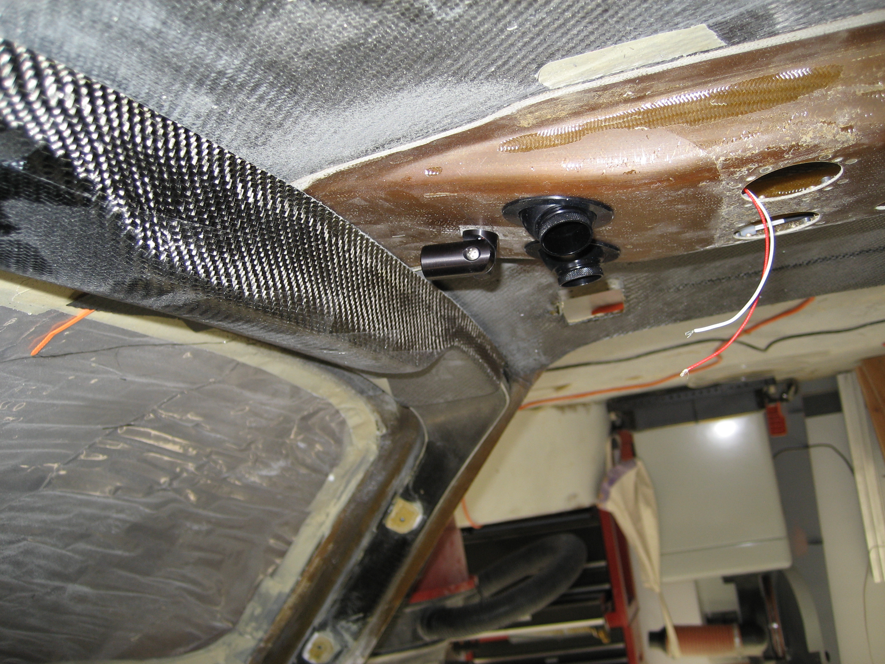
This is looking up at the roof. At the bottom-center is the top of the pilot side door opening. Top-center is the top of the co-pilot door opening. On the left side of these door openings is the overhead beam. This overhead beam (and the B-pillars which run down the side in back of the door openings) are made of carbon fiber. In order to get a hardpoint for the shoulder harnesses to mount to, I was going to have to remove this, install the hardpoint and re-install it. That’s when I made a couple discoveries. 


  • The B-pillars and overhear beam are not a single unit. They are three separate pieces.
  • Where they are tie in is not the most impressive union I’ve ever seen.
  • The roof has a layer of carbon fiber BID… but only one layer. (Notice in the previous picture that instead of solid black, you can see some “tan” between the rear beam and the windshield.)


2009-10-24 1245 IMG_9457
Here’s the joint between one of the B-pillars and the overhead beam.

2009-10-24 1246 IMG_9458

And here’s a closeup. No reinforcing layups. Just some epoxy.

The first thing to do is remove the overhead beam. To do this, I scored the 2-BID layup where the beam meets the roof. Then using a putty knife, I separated the BID from the beam at one end and then literally peeled it away from the beam. Then repeat for the roof. Next I made a couple small cuts at the joints on each end, a couple whacks with a chisel and the beam came right out. 

      2009-10-29 2007 IMG_9476

Next I smoothed out any rough areas and sanded the entire forward roof area and lay down an (additional) layer of carbon fiber BID.

2009-10-30 0804 IMG_9479

Once that cured, I decided to do an additional task. Most builders have a hard time getting the doors to fit after installing the engine. This is due to the weight of the engine causing the fuselage shape to change slightly. A few builders have installed some diagonal layups on the roof from the rear to the front to prevent the distortion. I used two plys of a fairly thick carbon fiber UNI that will help with the distortion and will add to the strength of the roof. 

2009-11-01 0948 IMG_94832009-11-01 0948 IMG_9484

Next I needed to locate where the hardpoint for the new (improved) shoulder harness will be. I did this with a plumb bob and a tape measure. The hardpoints for the diagonal shoulder harness is a piece of 2″x4″ wood. Two problems with that method for the new hardpoint. #1 is that the B-pillar is much deeper than the overhead beam (the beam is only 5/8″ deep) and #2 is the factory hardpoint uses a bolt sticking out. So I’m going to use a 3″ x 4″ x 1/2″ piece of aluminum that’s drilled and tapped. For most hardpoints, they use 2″ x 2″ x 1/8″ so mine will be much more substantial.

Here’s my hardpoint and the standard sized hardpoint.

2009-11-03 1356 IMG_94882009-11-03 1356 IMG_9489

Once the hardpoints are secured with structural epoxy, I drilled and tapped them.

2009-11-04 0925 IMG_9490

Before installing the beam I glued down a small square of titanium on the ceiling where the bolt for the hardpoint would come through. Just in case a too-long bolt was used, I didn’t want it going through the skin.

2009-11-04 0925 IMG_9492

I need to bond the beam in place. I want the overhead beam to become part of the of the B-Pillars to create a seamless rollcage. So I took 2 layers of leftover carbon UNI and inserted them into the ends of the B-Pillar. I then stuffed some foam under the layups to force it into contact with the inside of the B-Pillar.

2009-11-04 1024 IMG_9493

Then I applied some structural epoxy to the bottom edge of the beam and pushed into position. The foam under the layups will also force it into contact with the inside of the overhead beam. I then put the beam in place with a couple bricks on top to hold in place while the epoxy setup. Then I used some more leftover carbon BID over the seam with the B-Pillars and over the beam and onto the roof.

 2009-11-11 1615 IMG_9528


7.7.3 Main Gear Doors

This entry is part 32 of 39 in the series 07 - Landing Gear

The main gear doors are supported at the bottom by a piece of 1/8″ aluminum that gets cut so that it has four “fingers”. The aluminum supplied with the kit wasn’t as big as I would have liked, so I bought a larger piece and cut it to the correct shape. Then it has to be bent to conform with the inside of the door. This is a bit of a trick since you can’t really see very well where to bend and it’s a somewhat complex bend. Lots of trial and error. And it’s almost impossible to get it in the exact position. If the aluminum isn’t perfectly flat against the door, once you tighten down on a screw, it will deform the door and it won’t align.

Malcolm give me a bit of advice: Once it’s as close as you can get it, cover the plate with duct tape, apply a glob of epoxy/cab-o-sil and then lay the door down. Once it cures, you have a small “pad” that conforms perfectly to the support plate.Then a quick cleanup of the pads and you’re all set.

2009-11-23 1449 IMG_9564

Then holes are drilled through the door and the plate.

2009-11-15 1107 IMG_9544

Next, Nutplates are mounted.

2009-11-15 1109 IMG_9545

I don’t have a jig that determines the location of the holes for the nutplate, so I temporarily mount it and use it as the drill guide.

2009-11-15 1126 IMG_9546

Here’s another view:     

2009-11-23 1448 IMG_9560

That takes care of where the door attaches at the bottom. The factory says to attach the top of the door after the bend. Here’s the diagram from the manual:

2009-11-01 IMG_0381

But with the flexing of the gear leg, it seems that will cause cracks  to appear in the door where it has the 90 degree bend. So I beefed up the bend and put the mounting tab just before the bend.

This where I put the tab.

Another thing I did different is instead of using a piece of aluminum angle and screwing it to the door (which would leave a visible screw on the outside), I glassed a tab onto the inside of the door.

Here’s the tab on the gear leg.

2009-11-23 1448 IMG_9562

Another view of the inside of the door.

2009-11-23 1448 IMG_95632010-04-04 0657 IMG_0378

When you’re done trimming and mounting the door, it looks like this from the back.
2010-04-04 0650 IMG_0376

This is the top of the door from the side.
2009-11-26 1411 IMG_9575

That big honkin’ gap is there because when the gear comes down, the door would hit the fuselage and prevent the gear from fully extending if it was any longer. I guess the theory is no one will notice it’s there when the gear is down and the only time the gear will be up is where it’s in flight. But I’d know it’s there.

A couple emails to Malcolm revealed that I COULD have saved the extra to use a small door to cover the opening. But I couldn’t do that because I used the “sneak up on it” approach when I located the final position of the cut.

So I covered the side of the fuselage next to the gear door and laid out a few layers of triax and BID (so it would match the curvature of the fuselage). Then I cut it to fill the opening. To accomplish this, I used the tape-it-to-the-outside-and-shine-a-light-from-the-inside method to locate where to cut.

2009-11-23 IMG_9554

Then I cut and drilled a pair of hinges and did a dry fit. 
2009-11-23 1344 IMG_9555
Yep, it moves.
2009-11-23 1345 IMG_9558

I riveted the hinge to the mini-door and put nutplates on the side that would mount to the fuselage.

2010-04-04 IMG_0387 2010-04-04 IMG_0383
 Next I beveled the edge and built a flange so it would fit with the door.

2010-04-04 IMG_0382

Here’s how looks all installed and operational.

2010-04-04 IMG_03862010-04-04 IMG_03852010-04-04 IMG_0384

6.9 Overhead Fresh Air Plenum

This entry is part 34 of 42 in the series 06 - Fuselage

Here you can see the duct for the fresh air in between the two engine cooling NACA ducts.

IMG_5734

On the inside, there’s a plenum that runs from the rear up to the front. I’m going to install four eyeball vents (one for each seat) and four lights. The electrical lines for the lights will also be in the plenum. Determining the location of the vents and lights will be a little tricky since the seats aren’t in and the airplane is upside down so I’ve got to guesstimate their location.

Here’s one of the vents that I’m going to be using.

2009-11-11 1616 IMG_9530

I forgot to get a picture of the plenum before cutting the holes for the lights and vents. But here’s the front of the plenum after the holes are drilled for the vents with one of the vents installed.

2009-11-11 1617 IMG_9532

Here it is mounted in the plenum.

2009-11-11 1617 IMG_9533

Oops. Going to need to be modified. 🙂

Before and after.

2009-11-11 1618 IMG_9534

Here’s the plenum with the openings for the vents, lights and switches.

2009-11-15 0855 IMG_9535

The plenum with the vent, light and switch for the left rear seat.

2009-11-15 0856 IMG_9536

Closeup of the previous position.

2009-11-15 0856 IMG_9537

The lights are attached with 4 6-32 screws so I had to drill holes for the screws and nutplates.

2009-11-15 0931 IMG_9543

Can’t leave well enough alone. After talking with my A&P (Airframe and Powerplant mechanic) who used to work for United keeping their airplanes flying, he suggested an “all on” switch. A single switch that will turn on all the lights. Sounded like a good idea but it will require redesigning the lighting circuit board. This time, I decided to let the company that provides the design software make the board. It cost about $10 per board so I figured that I would try it.  While I was at it, I added a fourth white LED and used a single resistor for both sets of lights.

Here’s the new circuit board.

2009-11-18 1548 IMG_9553

Mounted and wired.

2009-11-18 1547 IMG_9551

From the inside.

2009-11-18 1548 IMG_9552

Test run.

2009-11-17 1919 IMG_9550

More Plenum Work

Because the air intake is on the top of the fuselage, water will be able to enter the plenum. So a drain is needed at the back of the plenum.

2009-11-23 1451 IMG_9569

Then I put a bulkhead just aft of the drain so no water would pool in the plenum.

2009-11-23 1452 IMG_9571

Finally, to prevent water from being forced up front and out the vents, I installed a small “half bulkhead” (a dam, if you will) between the intake and the vents up front.

2009-11-23 1452 IMG_9570

I was going to add the swivel map light at the front of the plenum. This would illuminate the overhead switch panel and could be used for a map light. For some reason, I decided to check the location. Good thing I did…

2009-12-17 1045 IMG_9580

2009-12-17 1045 IMG_9581

Two things wrong here: 1) it’s so close to the panel that it would only be able to illuminate a fraction of the panel and 2) it will interfere with accessing the switches. So it I decided to move it to the side and a couple inches back. While it won’t light the panel like I thought, I can still use it as a map light.

Before installing, I still need to paint it.