
In preparation for mounting the brake assembly to the wheels, I had
to remove the wheels from their axles. When I did, I received a very
unpleasant surprise. It would seem that when the wheels were mounted
on the axle at the factory, the bearings weren’t packed with grease.
The result was this:
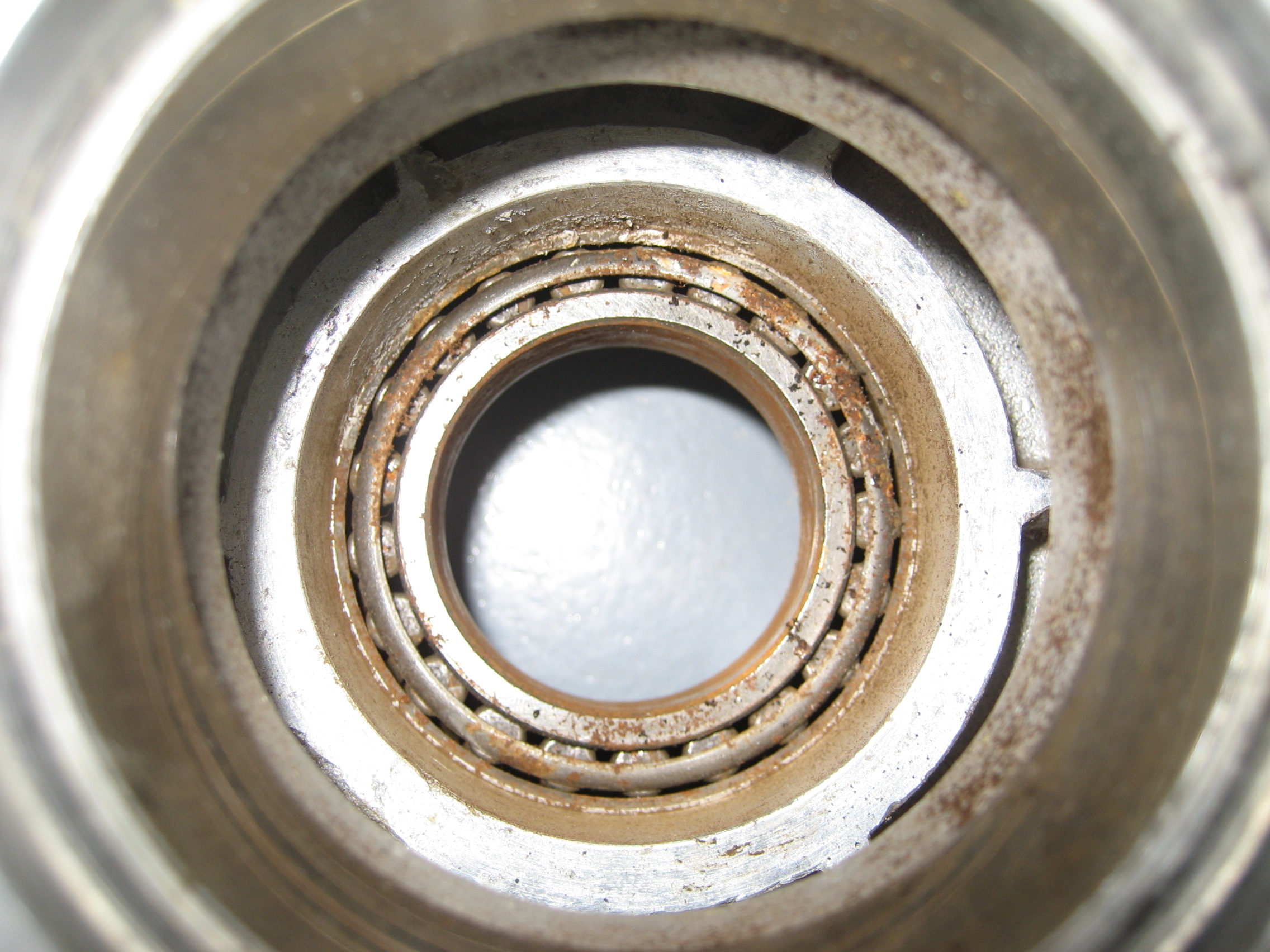
and this:

Only one of the races was rusted so that and all four bearings had to be replaced.
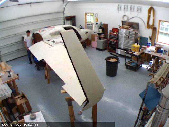
Category Archives: 2009
6.5.4 Install Nylaflow Tubing for Rudder Cables
The rudders (one of each winglet) are activated by cables that go from the rudder pedals to the back of the fuselage and then out the wings to the winglets on the end of the wings. On my Cessna those cables get from the pedals to the rudder by means of numerous pulleys. On the velocity, the cables go through a nylon tube (Nylaflow) down each side of the fuselage near the floor. The tubing is glassed in place. But at the rear of the fuselage, it has to transition from the floor to penetrate the gear bulkhead about 12″ above the floor. During operation, this unsupported tubing can flex and make for slop in the feel of the rudders. Another Hangar 18 solution is to support the nylafow tubing between the floor and the gear bulkhead by putting inside a short length of aluminum tubing.
Here’s the tubing on the left side. I haven’t pulled the nylaflo yet but it will go inside the aluminum tubing.
Right side
And here’s the finished product. nylaflo tubing installed and covered with a layer of BID.

Closeup of the aluminum tube where the nylaflo goes in.

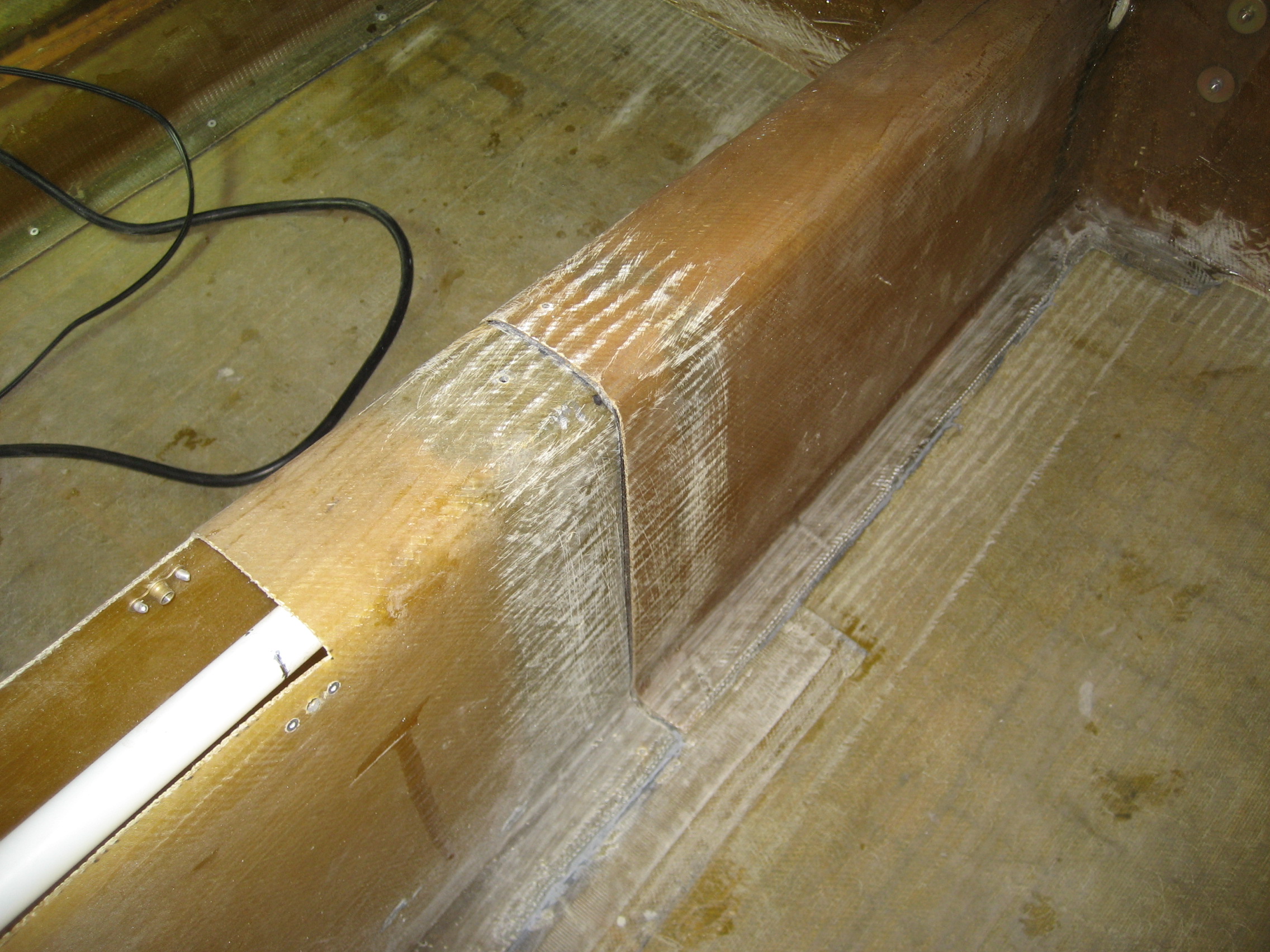
6.3.7 Install Aft Keel Section
This is going to require some explanation. The center keel runs down the center of the fuselage on the floor. It’s about 18 inches high at the front and drops to about 6 inches tall where it stops around 6 inches forward of the gear bulkhead. At the rear, it extends left and right to the sides of the fuselage. Inside of the keel is the aileron torque tube. Moving the stick left and right rotate this tube which causes the airplane to bank left and right. The only way to install the keel in a fastbuild kit is to cut it about 75% of the way back. Here’s a picture from February 2008 where Rick was preparing to make the cut. You can barely see the red “cut” line.

Front part of the keel after the cut.

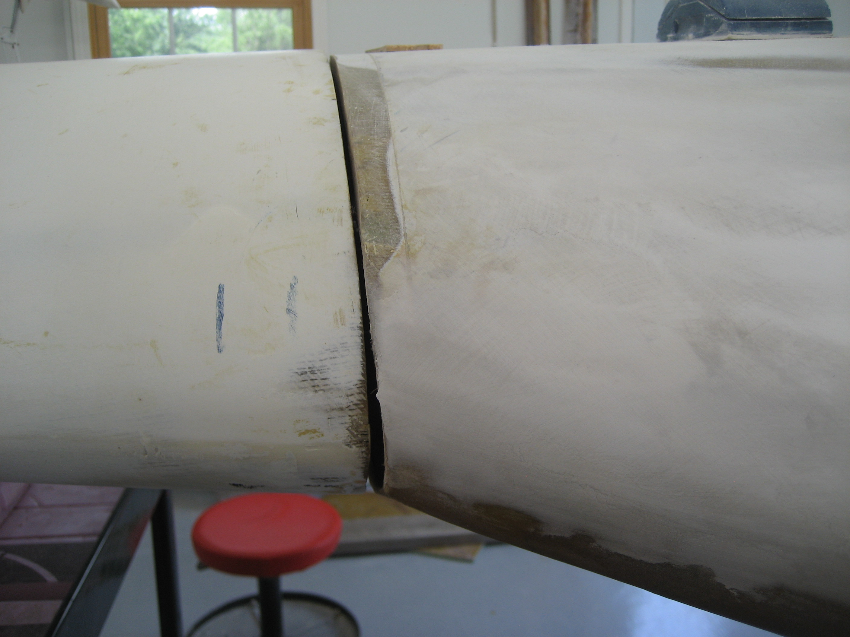
This part of the keel got installed when I was down in Florida. The smaller rear part is called the “Whale Tail” (you’ll see why later). So now I need to install this part of the keel. When I fitted it in position, it didn’t line up with the front part. Two possible reasons; 1) the mold used to make the keel has… warped and doesn’t conform with the floor of the fuselage anymore. Or 2), The mold to make the floor of the fuselage has warped with the same result. Or it could be a combination of the two. In order to get everything aligned, I had to remove some of the material along the bottom rear of the whale tail. The farther back, the more material I had to remove. As I moved forward, less had to be removed.
Here’s the whale tail in position (see why it’s called a whale tail?). In the bottom left corner of the picture you can just see the seam with the forward part of the keel. Where the keel meets the floor is a flange that lays on the floor. But in the back you can see where I had to remove the flange so it would sit correctly.

The seam where the rear keel section attaches to the front.
Where there’s a flange that contacts the floor, structural adhesive is used to bond the keel to the floor. Where I removed the flange, BID layups will be used to strength.
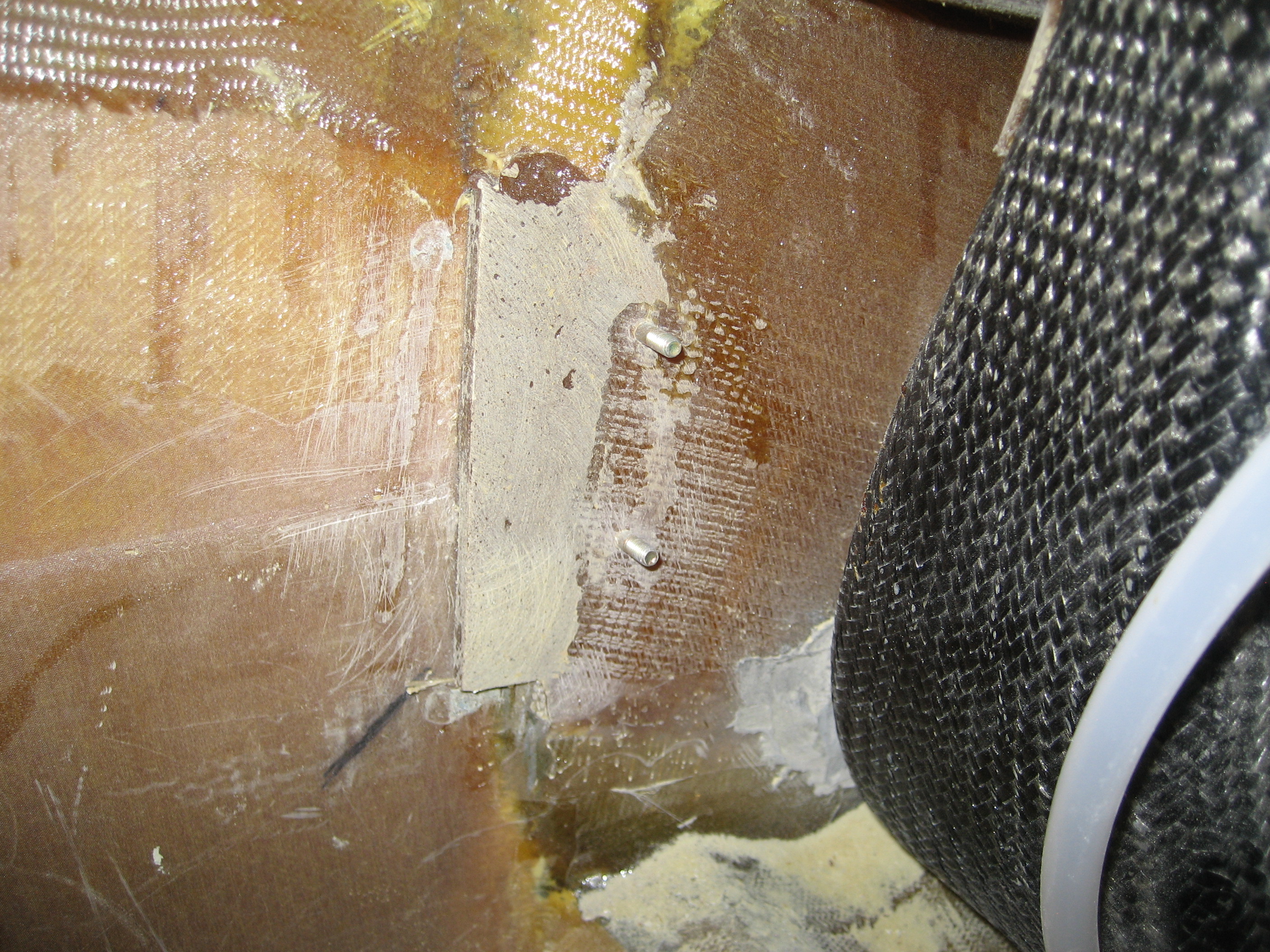
Here’s the left side of the whale tail where it contacts the wiring duct. You can see a bit of the gray structural adhesive used.
Next I created a fillet of epoxy/micro and then covered the flangeless areas with 2 layers of BID front and back. Here’s the same location with the BID layups applied.
Chicken strips
On the rear portion of the keel where I didn’t have to remove the flange and the entire front portion of the keel it’s attached to the floor with only structural adhesive.
Here’s the right side of the keel about half-way back.

Close-up of the same area.

Normally, in this type of joint you would reinforce it with two layers of BID. The manual doesn’t call for this, but I’m going to do it anyway. So I beveled the edge a bit, mixed up some epoxy/micro and then layed down two layers of BID. This will make it much stronger.

8.1 Matco Brake Upgrade
During the build, I learn volumes from other builders. Through their websites (like this one), email, message boards and fly-ins like Oshkosh and Sun-n-Fun. One of the things I hear repeatedly is that the Matco brakes that come with the kit are awful. Both from a building standpoint (a pain to work with and around) and more importantly from a functional aspect. It appears that a common complaint is that the brakes feel mushy and brake fade is almost a certainty during heavy braking.
After hearing these stories I discovered that Velocity offers an upgraded braking systems from a different manufacture. Cleveland brakes are easier to work with and offer much better braking. But when I checked with Velocity, I learned since I had already taken delivery, I couldn’t exchange the brakes and that I would effectively have to purchase them outright.
Arrgh!
So I did some research. FAR (Federal Aviation Regulation) 23.735 states:
- Brakes must be provided. The landing brake kinetic energy capacity rating of each main wheel brake assembly must not be less than the kinetic energy absorption requirements determined under either of the following methods:
a. The brake kinetic energy absorption requirements must be based on a conservative rational analysis of the sequence of events expected during landing at the design landing weight.
b. Instead of a rational analysis, the kinetic energy absorption requirements for each main wheel brake assembly may be derived from the following formula:

where–
KE = Kinetic energy per wheel (ft.-lb.);
W = Design landing weight (lb.);
V = Airplane speed in knots. V must be not less than Vs √, the poweroff stalling speed of the airplane at sea level, at the design landing weight, and in the landing configuration; and
N = Number of main wheels with brakes.
Got that? 🙂
The brakes that I have are Matco model W600XT’s which have a “KE” rating of 337,932 ft.-lb.
I haven’t been able to find the rating of the Cleveland brakes, but they’re the same brakes used on a Cessna 210. Now the Cessna 210 is BIG airplane. Six seats with a gross weight of 3,800 pounds. By comparison, the Velocity XL-RG has four seats with a gross weight of 3,000 pounds.
Those brakes on a Velocity would clearly be enough, right? Not so fast… literally.
Reviewing the formula, notice the “V”. That’s the speed of the plane at landing.
Plugging the Cessna 210 specifications into the formula reveals a KE requirement of 292,996. Which means that you could use the Matco’s on a Cessna 210 with a 13% margin. So why are the Cleveland’s so much better at stopping? I suspect that the Cleveland brakes are rated a bit higher than the Matco’s. Probably around 350,000 ft.-lb.
So then I used the Velocity numbers in the formula. What I discovered is a KE requirement of…. drumroll please. 348,863 ft.-lb.
For me, this is a problem. Because the Velocity lands at 75 knots instead of 57 knots like the Cessna 210, the amount of additional braking energy required is significant. The Matco W600XT brakes are rated at only 337,932 ft.-lb. This explains the mushy brake complaints and fade after heavy braking. As far as I’m concerned, this changes the Matco-Cleveland issue from an “optional upgrade” to an “absolute necessity”. But the upgrade (which by my estimate would bring just within specs) was going to cost about $1,000.
So I did more research. I heard rumors of what I can only describe as a mythical Matco brake rated at 450,000 ft.-lb. I could find no reference to this “super brake” anywhere. No other builders have them, and no one has heard of it.
So I took a wild shot in the dark. I called Matco. 🙂
I was connected to an engineer and I explained my situation. He seemed… concerned that I was running W600XT’s on a Velocity. He said that I need W600XTE High Energy brakes rated at… wait for it… 450,000 ft.-lb.
So I asked how much they cost. He said “You’ve got 600XT’s?” I told him I did and he said that I could just replace a couple parts to convert the 600XT to a 600XTE (High Energy). “How much is that going to cost?” I asked, bracing for the response. “About $300” he replied. I ordered them on the spot.
Here’s the parts list:
WHLD6HE – High Energy Disc (2 required) $96.62
WHLBSP600XT-1 – Spacer (2 required) $39.29
WHLBSP6-1 – Spacer (4 required) $4.95
MSC.31-17×1.75HHBOLT – Bolt (8 required) $1.60
WHLBSP600-1 – Spacer (4 required) $4.95
WHLLM29700LA – Roller Bearing (4 required) $21.08
MSCAN4-21A – Bolt (4 required) $.60
MSCNL8 – Washer (8 required) $.69
It actually came to $416 (he initially forgot about the bearings), but still a bargain for better stopping power.
Here are the inside and outside view of the current brake system


Here are all the tools that I used:

First I removed the two nuts and bolts that hold the torque plate in position.

You can remove the torque plate at this point.
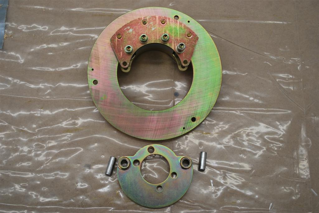
Next the four hex screws that hold the calipers in place.

Here it is disassembled.
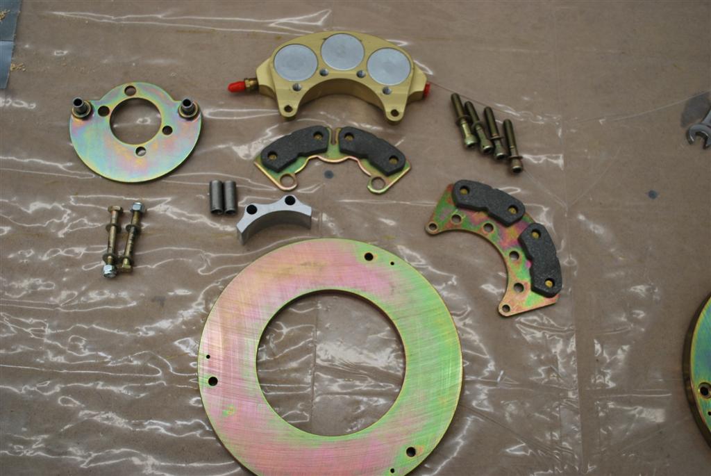
Then it’s just putting it back together in the reverse order while substituting the new parts for the old.
Here’s the end result. New W600XTE on the left.

In the upper right corner, you’ll notice a bag of bolts and washers. These are supposed to replace the caliper retainer bolts/washers. Originally, these are safety wired. Instead of allen-head screws that are safety wired, they sent me regular hex head bolts with some fancy locking washers. My guess is that when you remove these bolts the washers will have to be replaced. I’m going to call Matco to see if I can still use the old screws with safety wire. Otherwise, I’ll order a bunch of these washers.
The primary difference is the disc. It’s thicker and it has three angled grooves cut into the face. All the other parts simply allow the thicker disc.
Here’s a close up of the old and new disc.

Now this isn’t going to make servicing the wheels and brakes any easier. But I’ll be able to stop. 🙂
I’m still a ways off from finding out how well they stop but now I’m much more confident that I will stop.
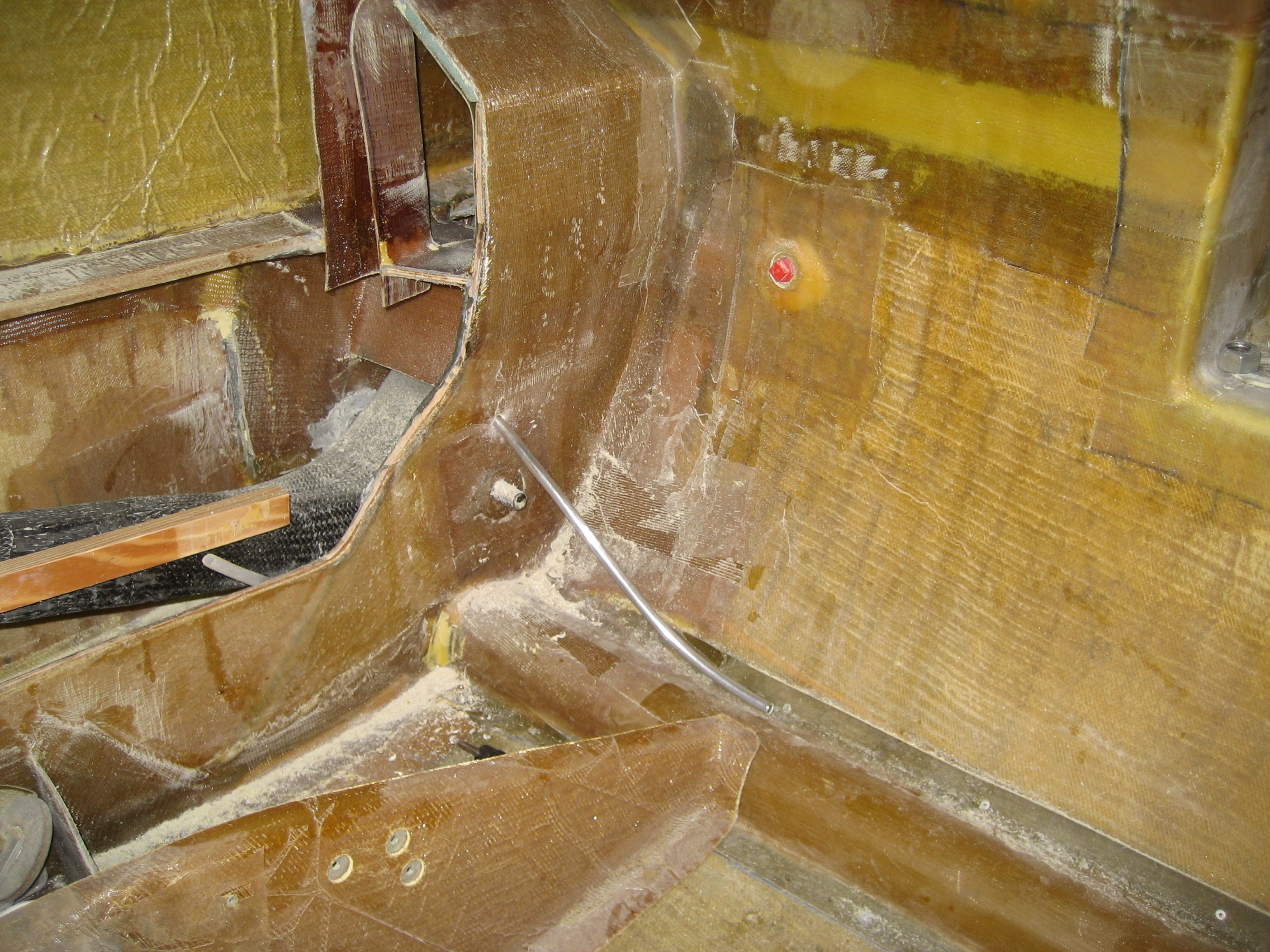
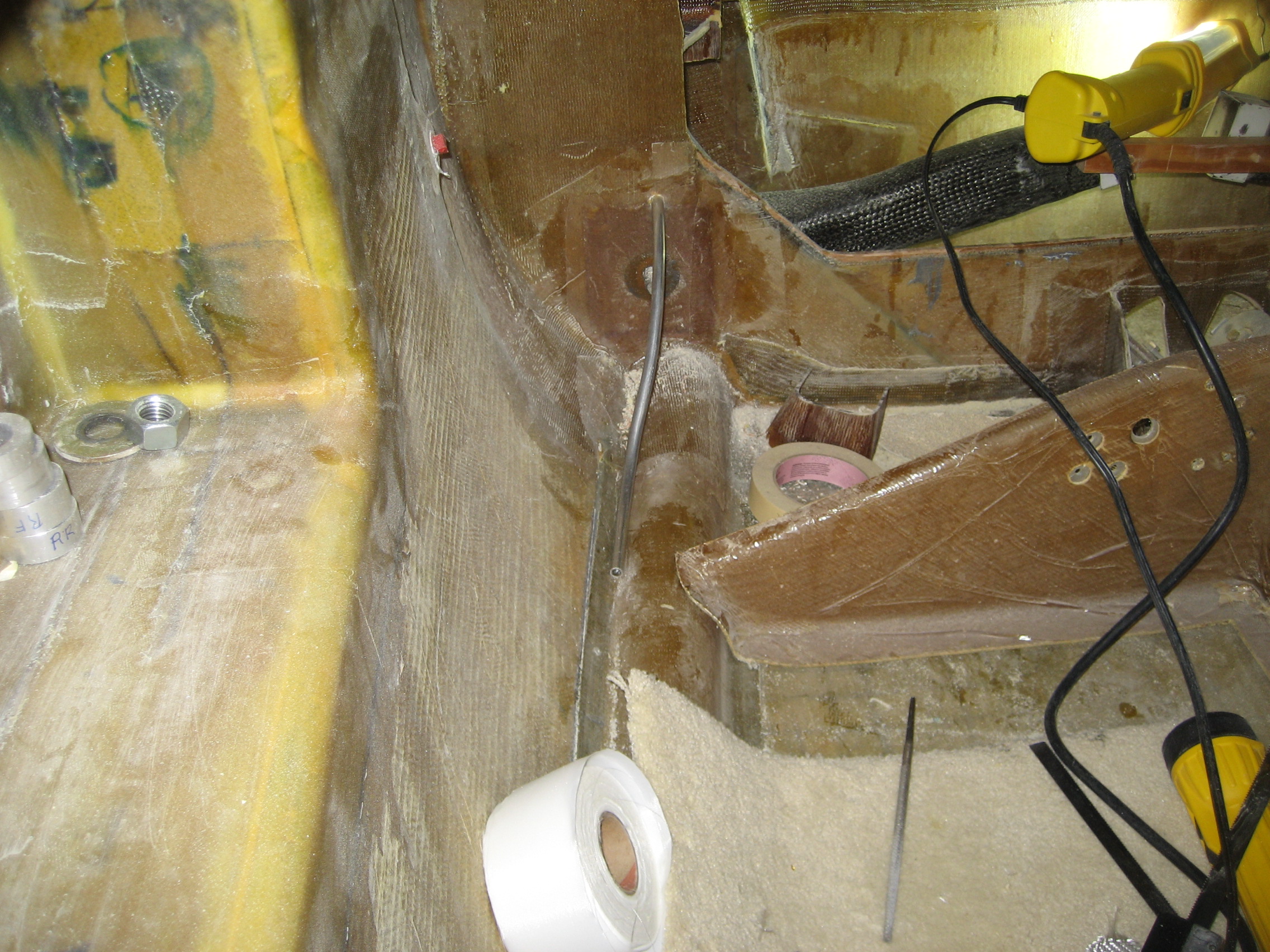
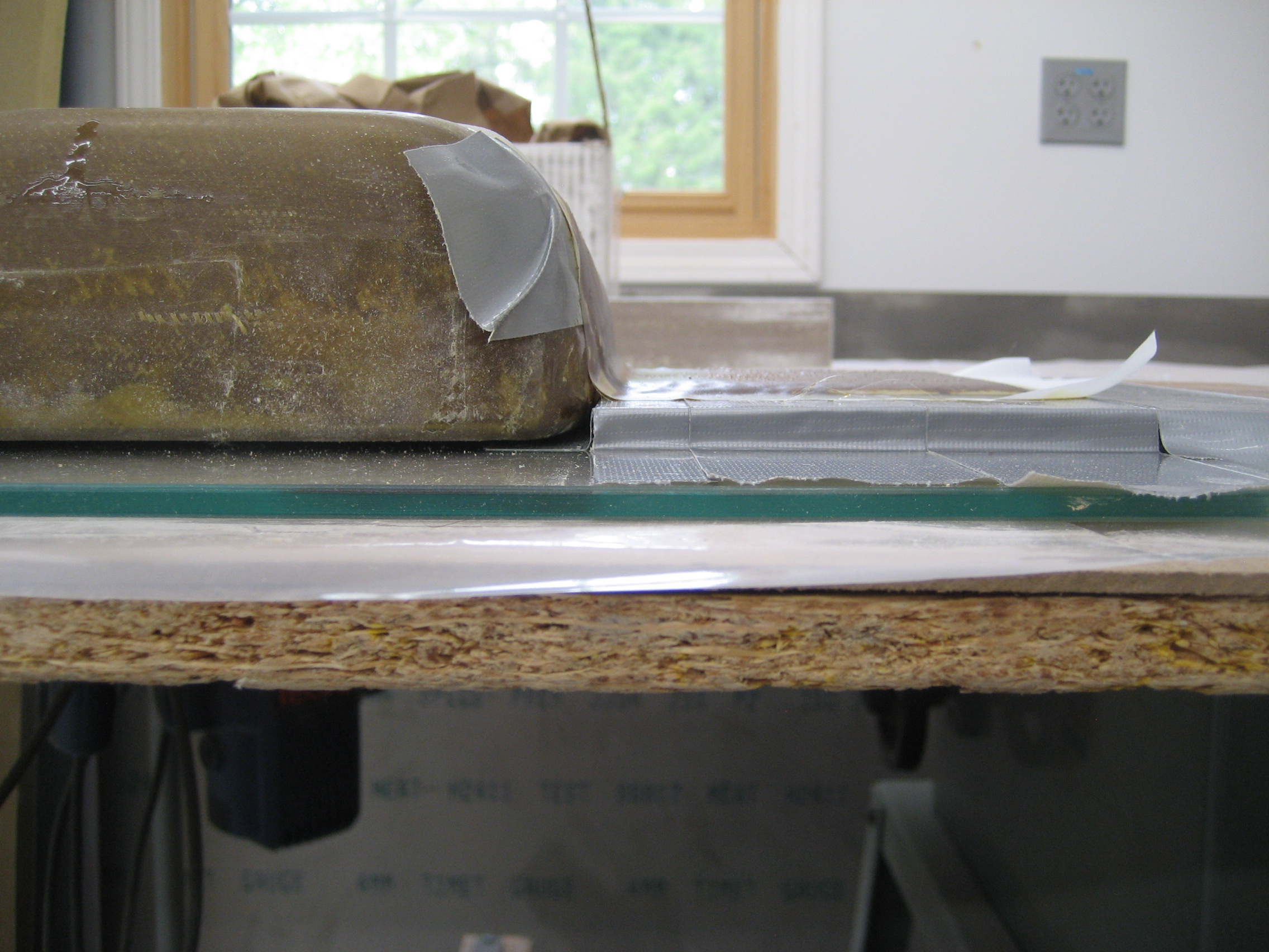
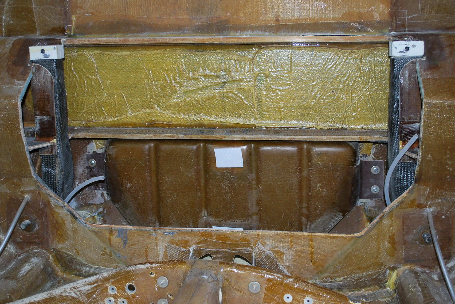
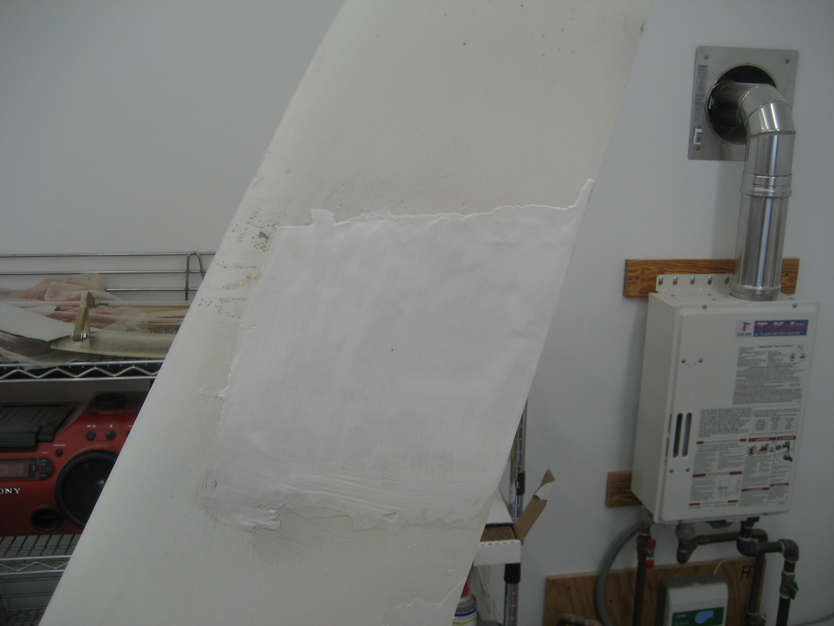
9.5.5 Sump Tank Installation
When I went to mount the sump tank, I had another surprise. This one was somewhat self inflicted. When I created the mounting tabs on the sump tank (according to the manual), I made them flush with the back of the tank.

The problem is that the surface where the tank mounts is not flat. Part of the transverse bulkhead layup extends out to where the tabs are. In this picture one edge of the sump tank is just to the right of the center of the picture. I could have left the original tabs on, but then the tank would be sticking out about a quarter inch from the firewall. So I ground off the old tabs.

And made some offset tabs. So I got my handy sheet of “Layup glass” (A Hangar 18 term for a big sheet of glass that you wax up) and made some risers for the mounting pads.


Then I put the glass and epoxy down and let it cure.
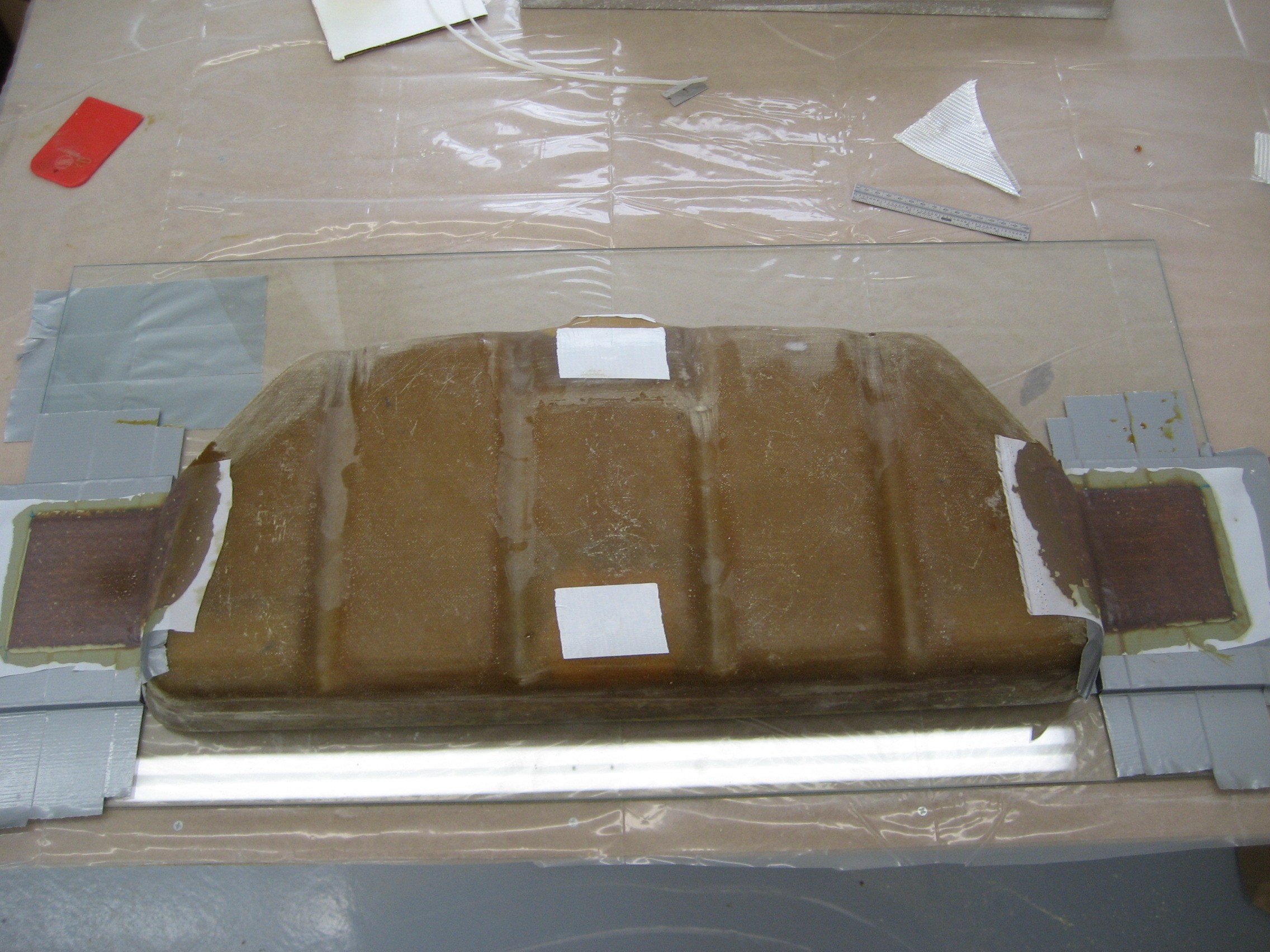
Finished sump tank with offset mounting tabs
To mount it you’re supposed to drill through the firewall and use a four bolts and nuts. But then you need two people to loosen or tighten the bolts. So I used a Hangar 18 trick. After I drilled the holes, I enlarged them on the firewall side so the head of the bolt would be lower than the surface. Then I put the bolts in and covered the heads with epoxy/micro.
Firewall side showing two countersunk bolts with epoxy.

Inside left view with the two bolts.
Sump tank installed and bolted in position.
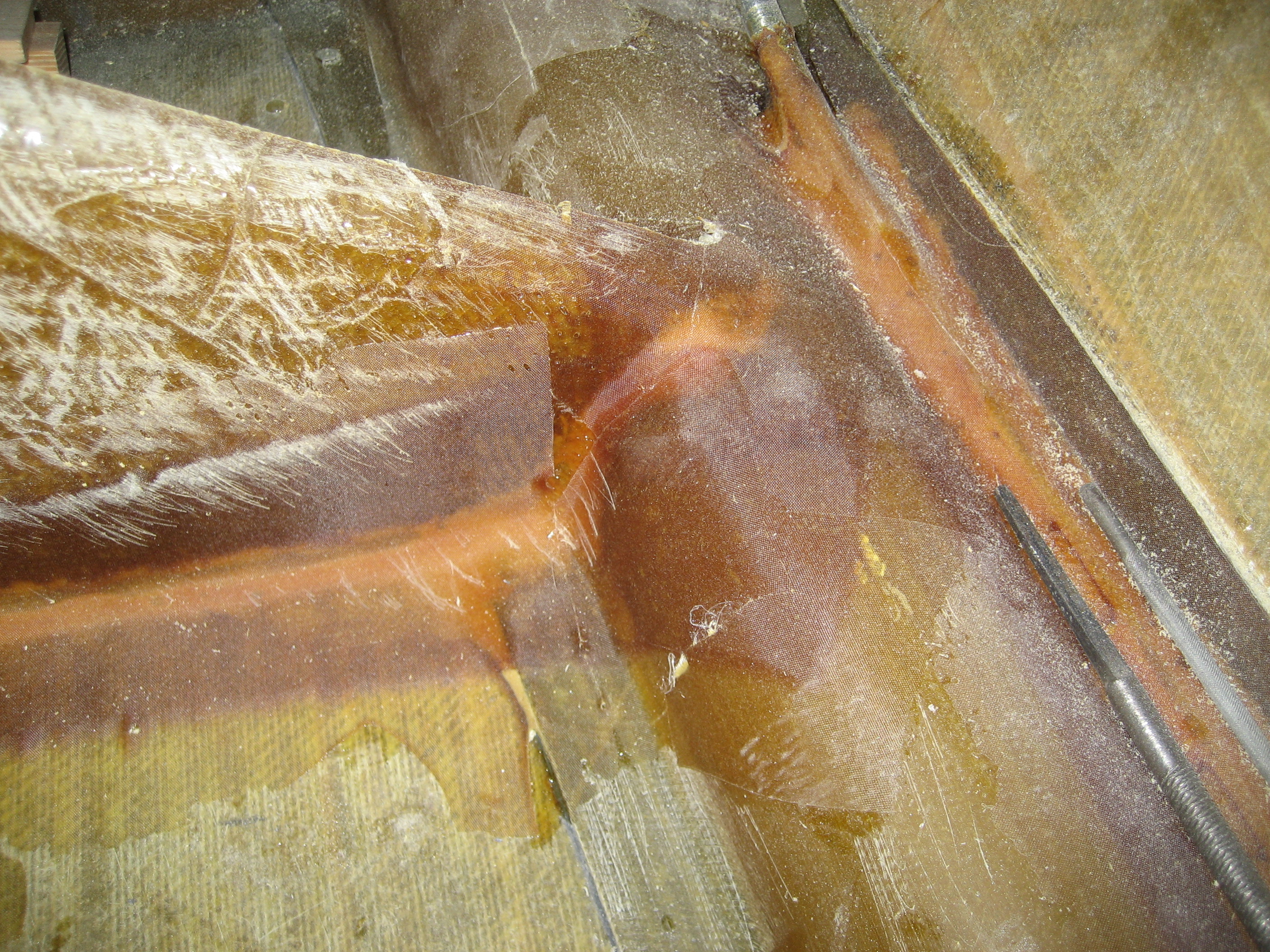
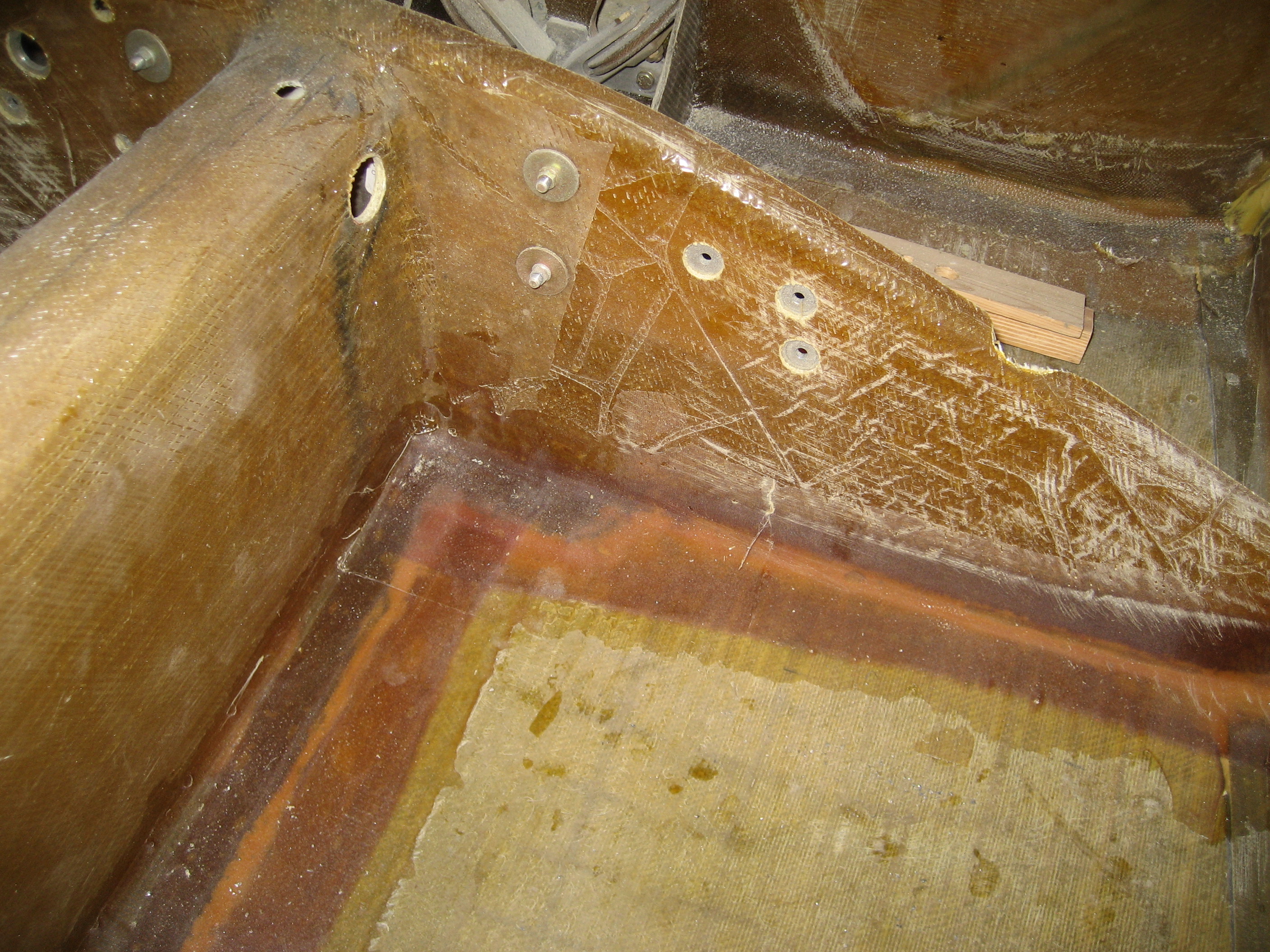
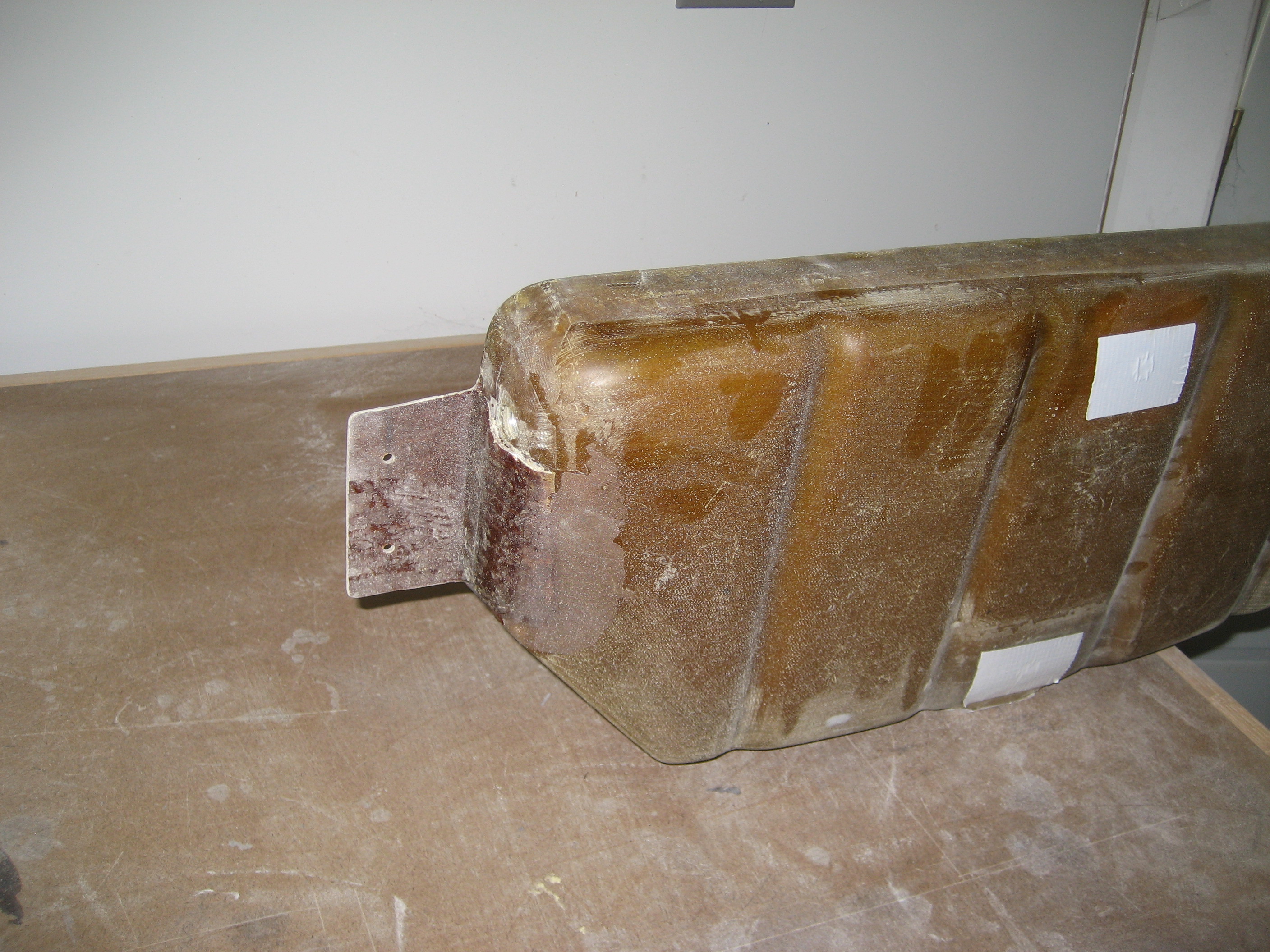
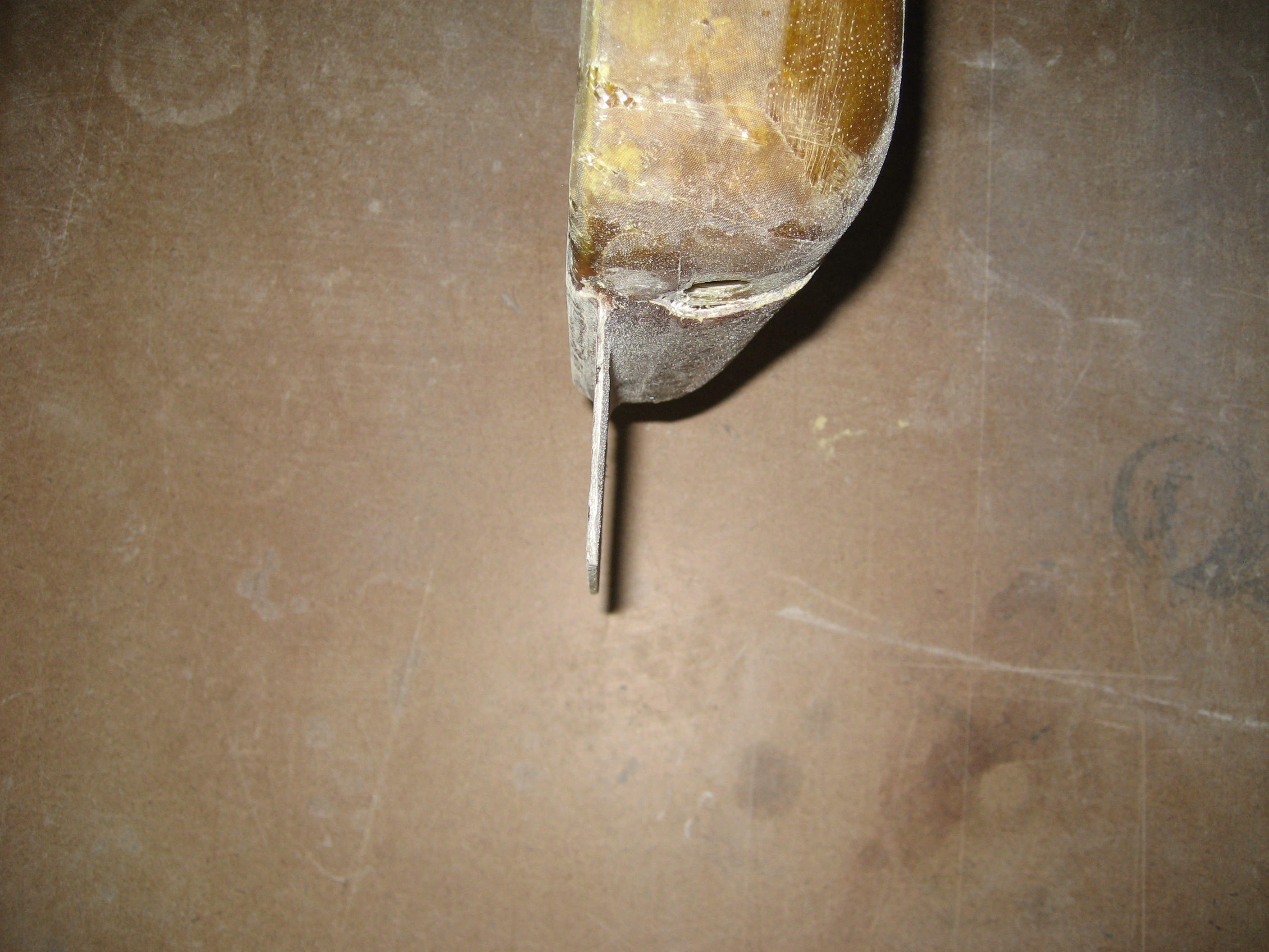
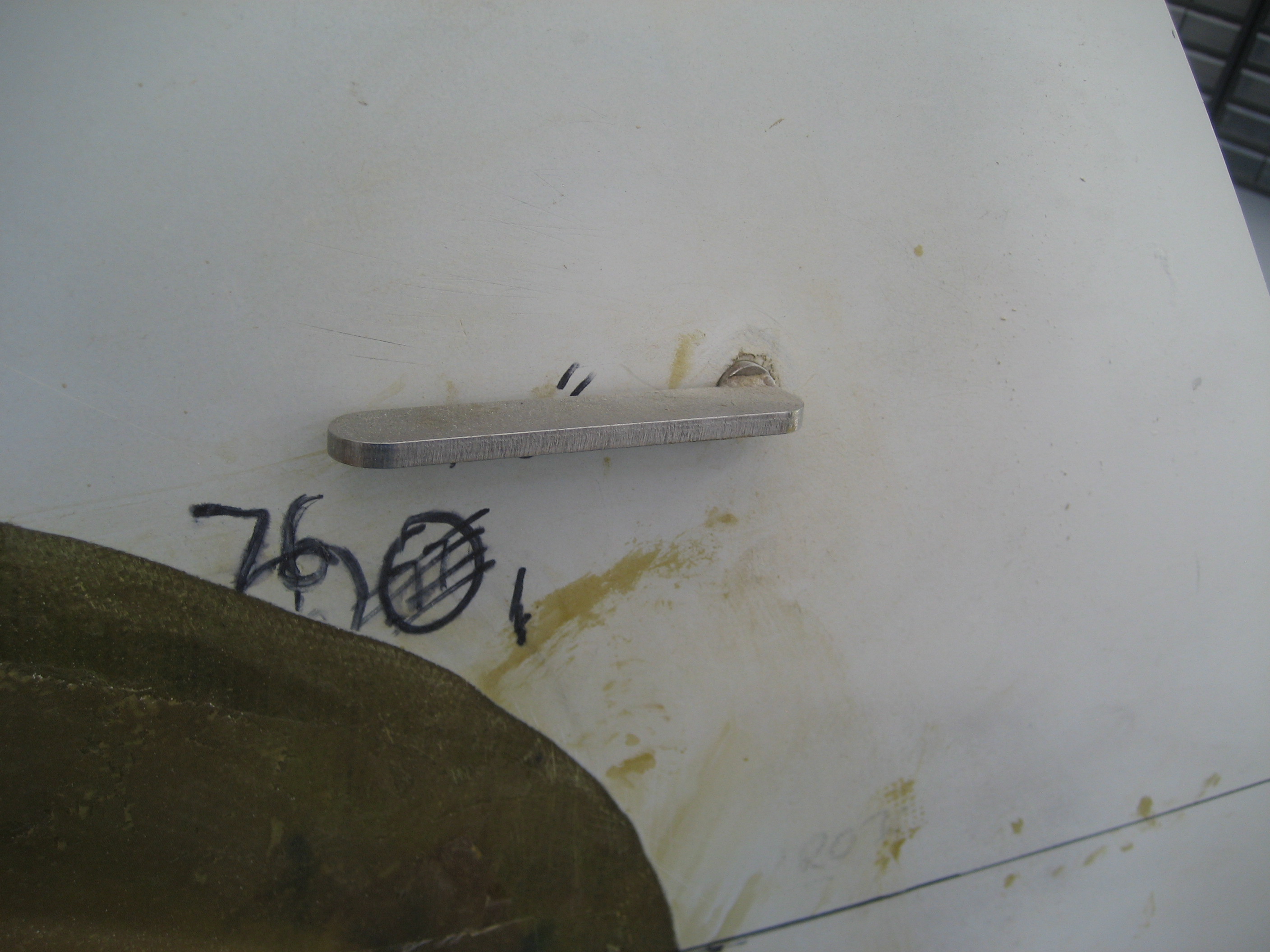
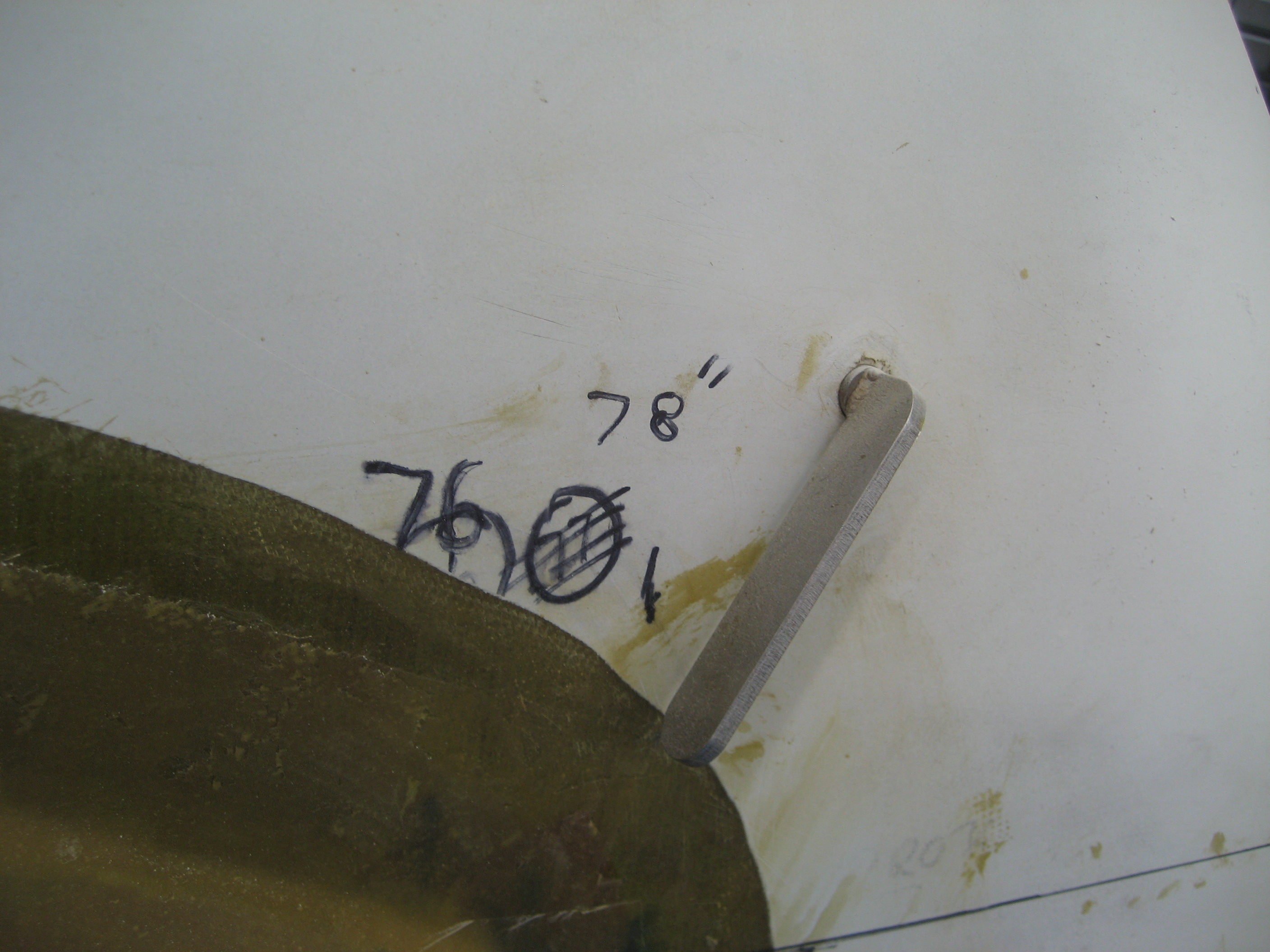
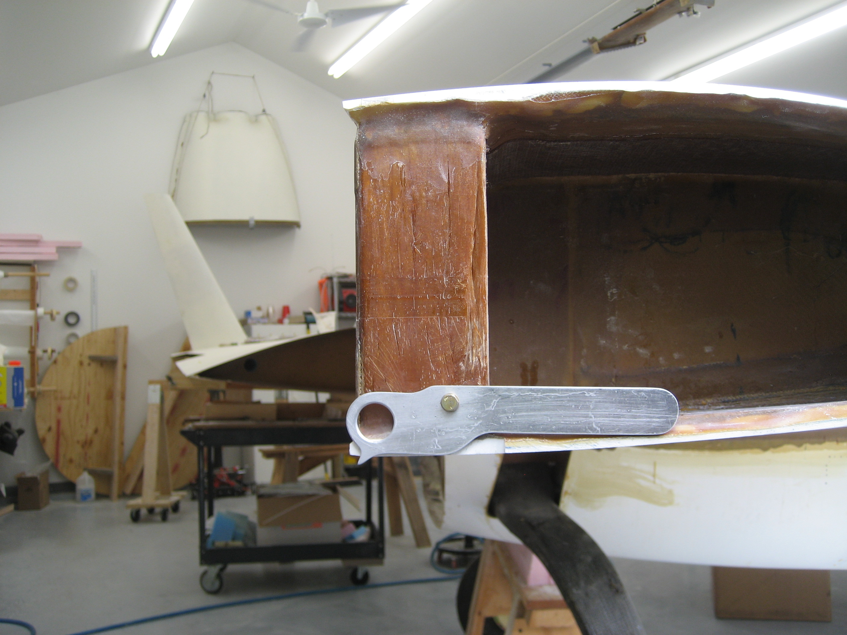
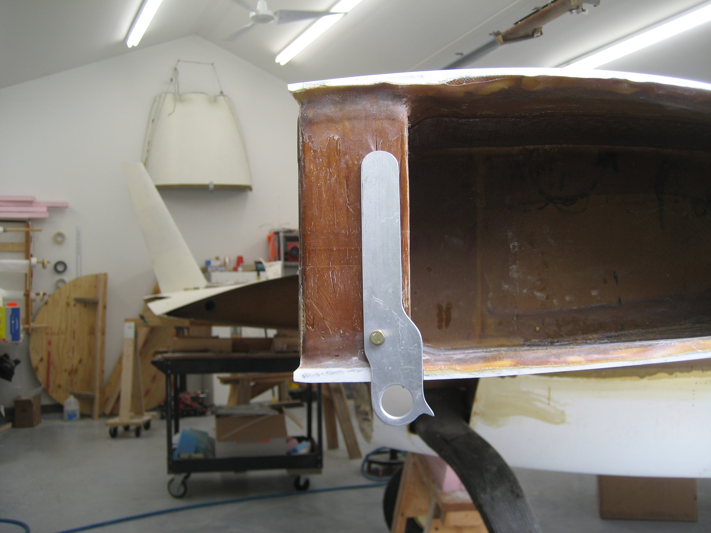
8.1.1 Main Gear Wheels and Axles
This is a fairly big job. Once I got the brakes upgraded, I need to get the wheels and brakes mounted to the gear legs. The first challenge is that the gear leg needs to be cut.
Here’s the bottom of the gear leg and the four holes that are used to bolt the axle and brake torque plate to the gear leg.

This is the gear leg side of the axle mounting flange.

Notice where the caliper is? Well not only does the gear leg have to be cut, it’s going to be cut REALLY close to those bottom holes. So the first thing that I need to figure out EXACTLY where to make that cut. I don’t want it any shorter than possible. To determine the cut location, I made a template from some masonite. It was basically trial and error but eventually I ended up with this.

Because black ink won’t show up on the gear leg, I applied some masking tape.

Then position the template with the four bolts.

And trace.

The next challenge was to make the cut. If the gear leg was made out of wood, I’d leave the template on and use a router. But the material used in the gear leg is TOUGH. So that’s out of the question. I would probably ruin two $25 bandsaw blades cutting the two gear legs. Malcolm at Hangar 18 suggested using Permagrit blades in a jjigsaw. About $3 for a blade and it went through the gear leg like butter.

The heat generated by the brakes could cause the gear leg to weaken over time. To prevent this a heat shield is used. The factory ships a “phelolic” sheet with the kit that is placed between the gear leg and the axle/brake/wheel assembly. I elected to upgrade to a material called “Garolite”. This has much better heat shielding properties. It’s pricey (about $50 for a sheet) and the minimum size is enough to make four shields. But after I made mine, I sold the remaining stock to another builder so it only cost $25 for both gear legs. In aviation money, that’s a bargain!

To cut the material, I used my template again. First I clamped to the Garolite to the template and marked it.

Then I cut the Garolite with the jigsaw and cleaned it up with a carbide burr.

To allow movement of the brake caliper through it’s entire range, I had to create a notch for the upper torque plate mounting bolt.


Once I mounted everything, I had to disassemble everything and grind off material from the gear leg here and there until all the parts had necessary clearance. I probably mounted and removed the brakes over a dozen times.
Here’s the end result.


2.3.2 Winglet Repair
You may recall that when the airplane was brought back from PA, the
right winglet sustained some shipping damage.
To fix it, I had to grind the surface filler down to the fiberglass
and trim back the fiberglass. Then I had to cut out the foam.

Next, create a “plug” and bond it in place with epoxy/micro.

Then cover the entire area with two layers of UNI and the first coat of filler.

2.6 Wing Finishing
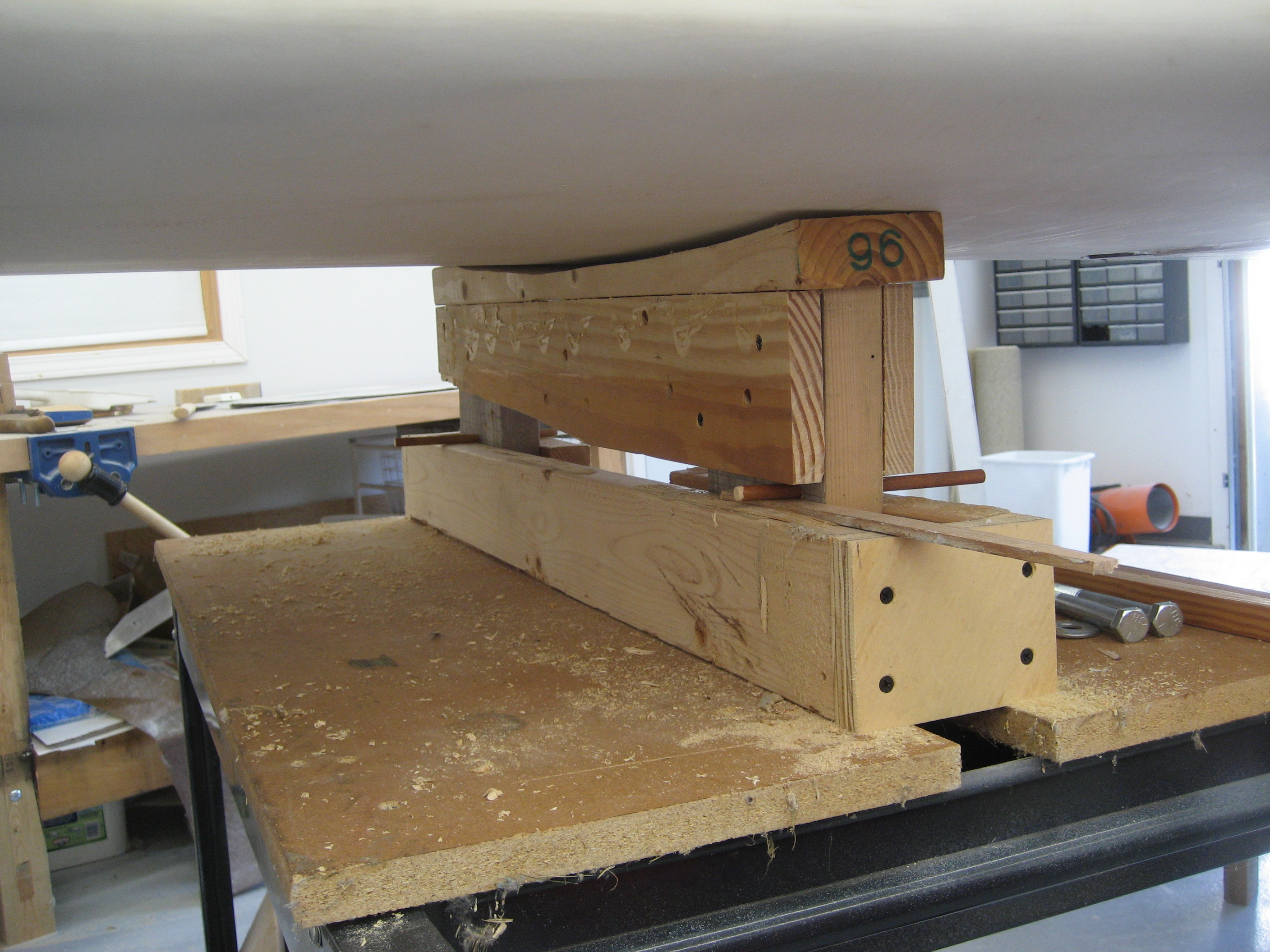
Where the wing root meets the strake has to be finished. Here I discovered that there was a bunch of work required. In order to accomplish this task, I had to rotate the fuselage so I could fit a wing on. For the most part the fuselage has been sitting like this:

But now it looks like this:
And here’s me and my son Steve bolting the wing on:
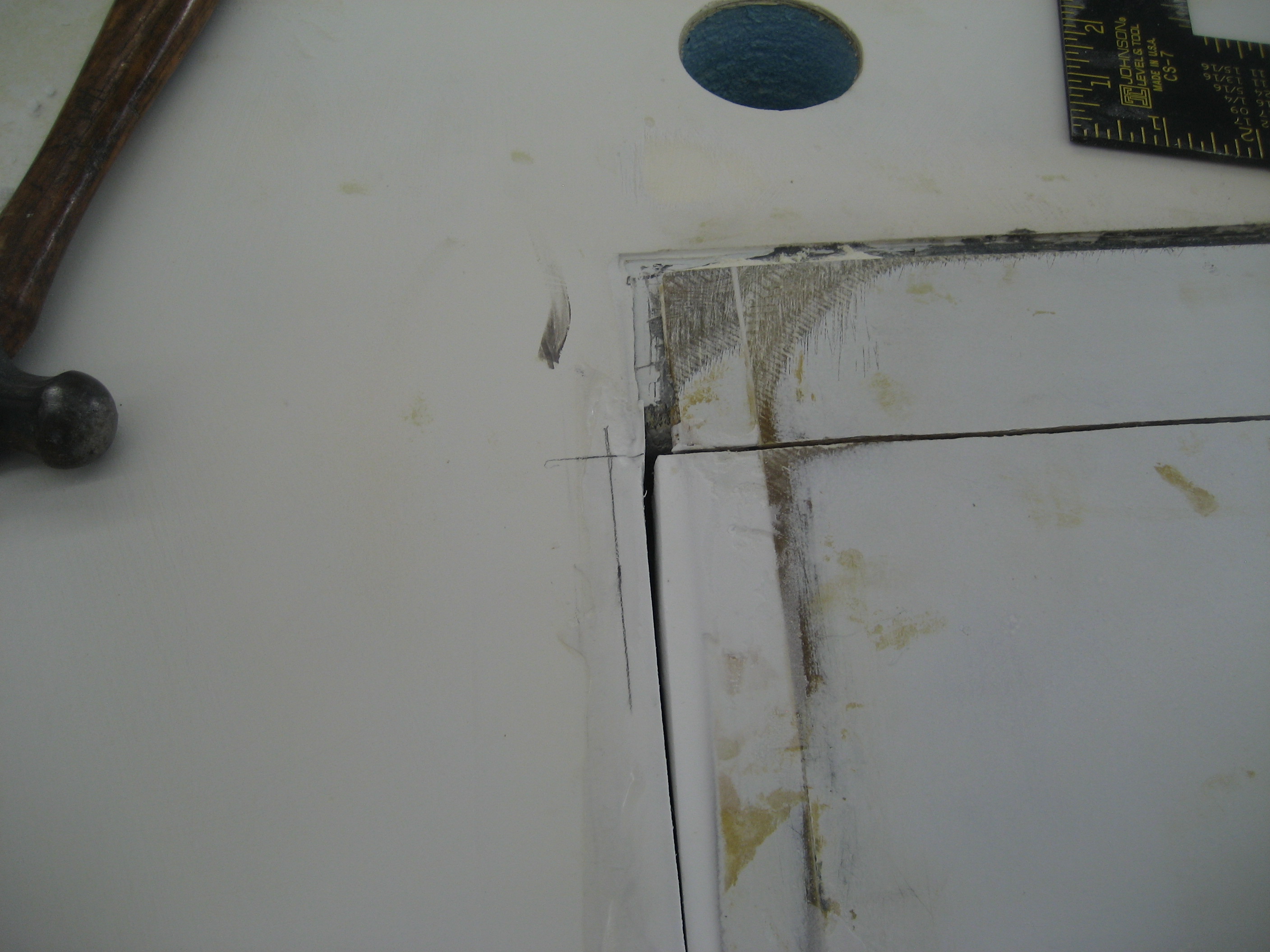
Once I got the wing on I discovered a bunch of work that needed to be done. Here the front view of where the strake (right) meets the wing (left). Kind of a large gap. It should be about .030″.
Almost a 1/2″ inch gap here.

And here you can see the strake ends about 1/2″ forward of the wing.


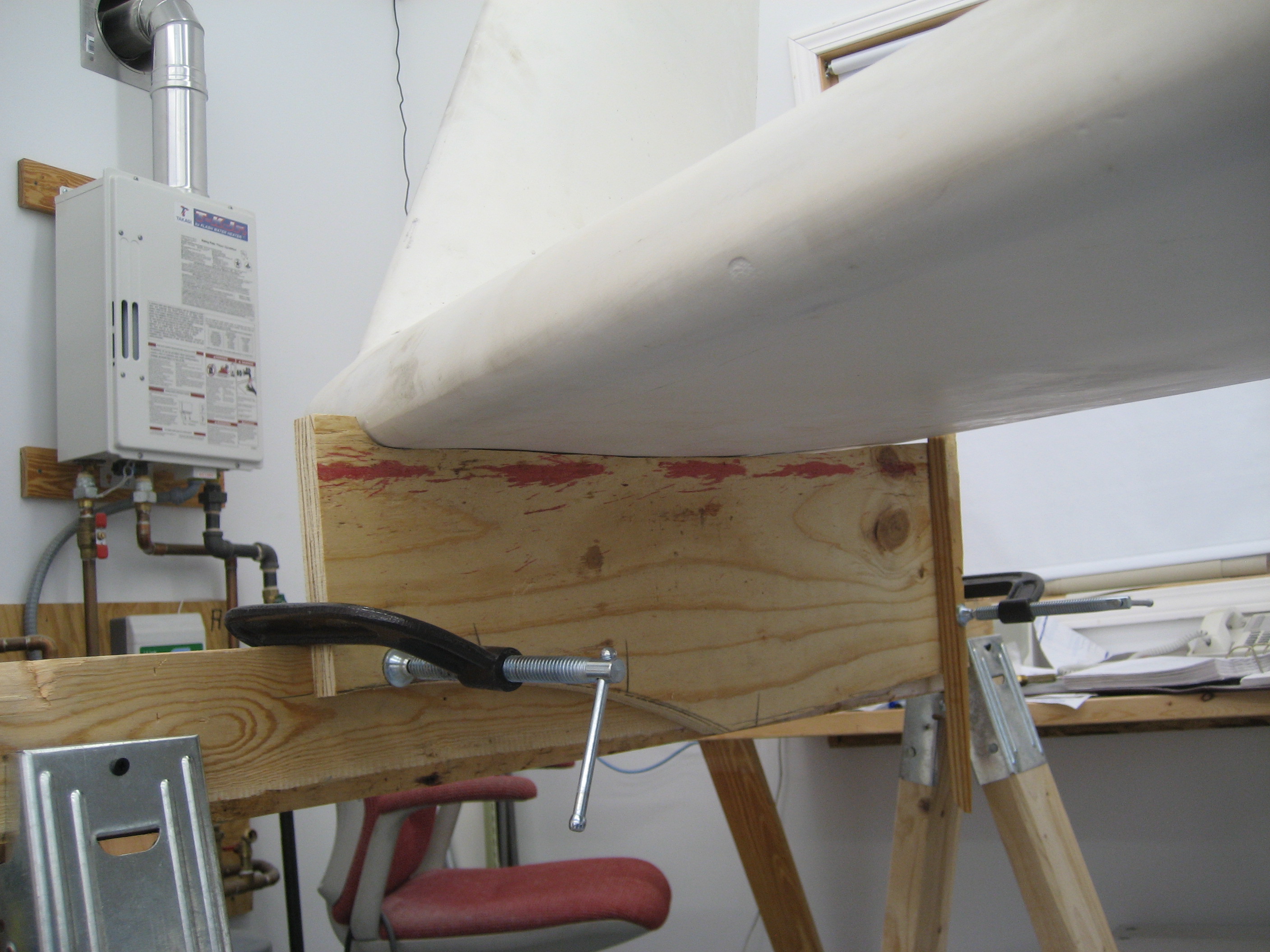
Now to fix this was going to require me to take the wing off and put it back on numerous times. And much of the time building I’m alone so first I needed to make this easy to accomplish. So I build a couply moveable stands. Here’s the one for the wing root end.

By raising the cradle portion, I can insert some dowels and shims to obtain infinite positioning.
For the wingtip end I went low-tech. A sawhorse that sits on my wheel dollies. A true multi-tasker. Alton Brown would be proud!


At first I toyed with the idea of simply filling the void. But that resulted in a rather wavy seam. So I determined where the seam should be and drew a line. Here’s the rear of the joint.

Then I put a placed a straight-edge along the leading edge of the strake and marked where it SHOULD meet the wing and marked that.

Now how to connect the mark at the front to the mark at the rear??? LASER!

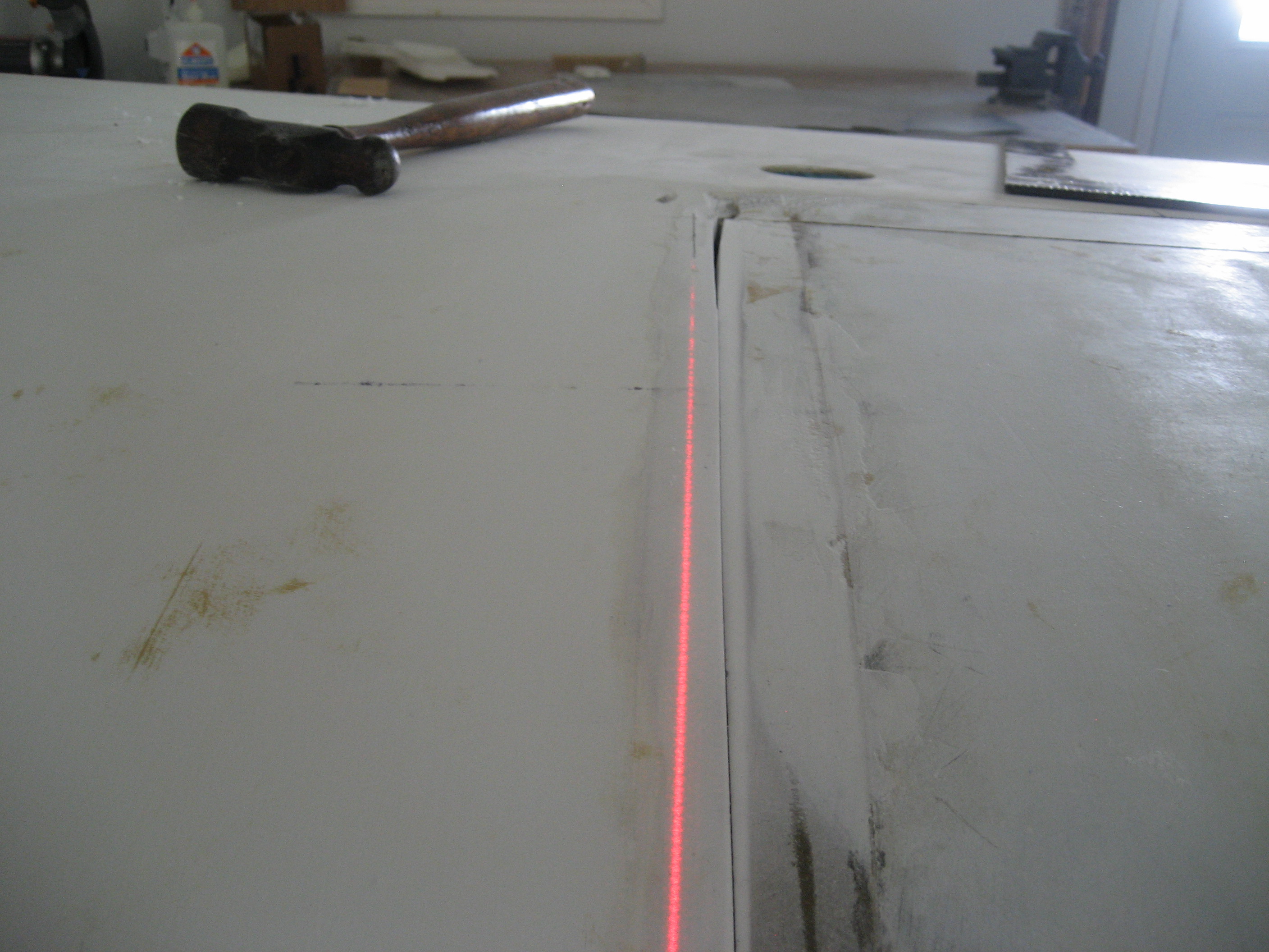
With the laser positioned to create a beam from the front mark to the rear mark, I had to perfectly straight line. You can see here that my attempt to create the line wasn’t exactly straight.

So I erased my first marks and created a line where laser indicated.
I have a really tough time sawing a straight line using a pencil (or pen) line. Malcolm gave me a great tip. Lay down some contrasting masking tape on the line. It’s easier to follow that way.
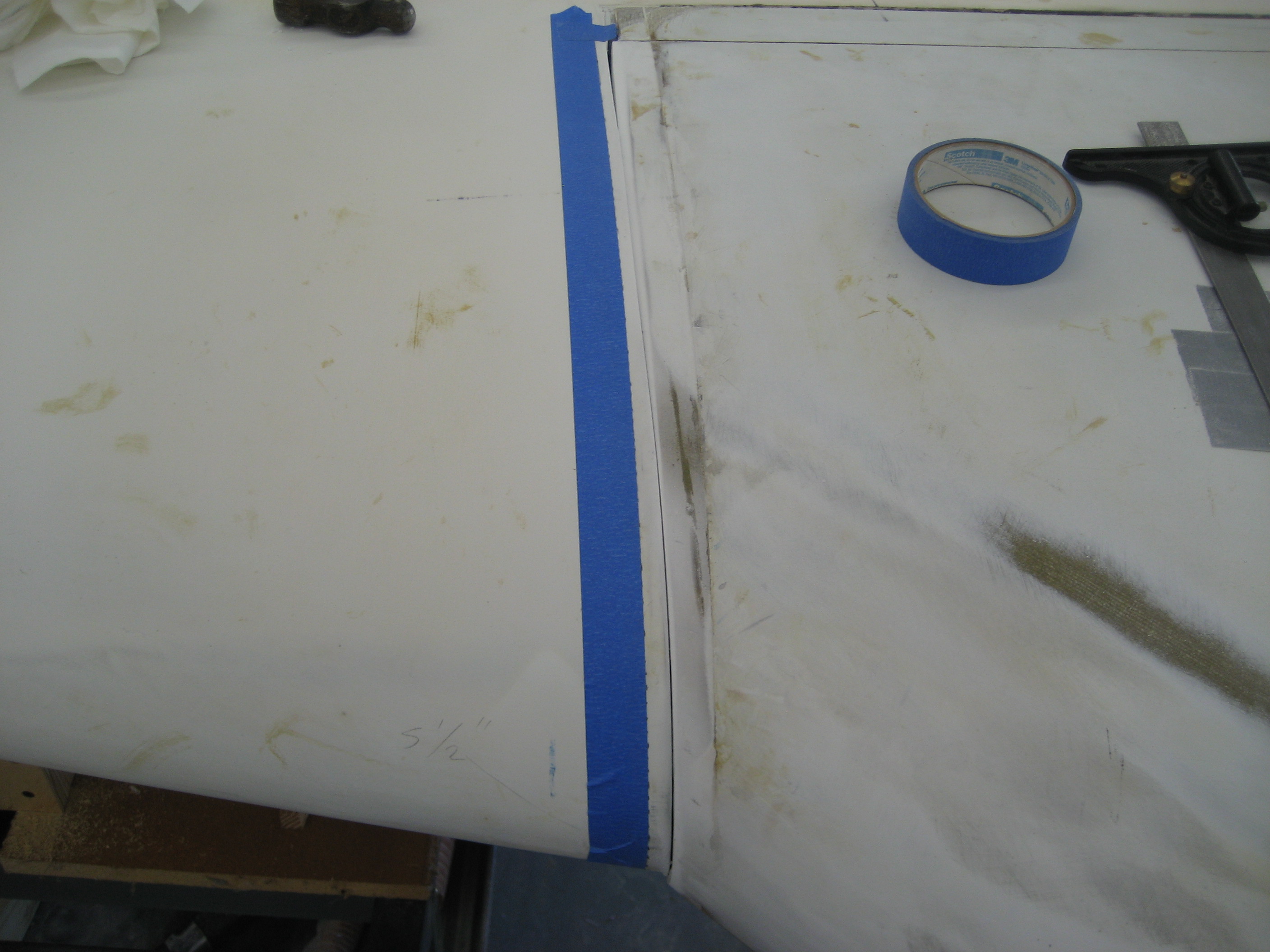
I made the cut and removed the wing.

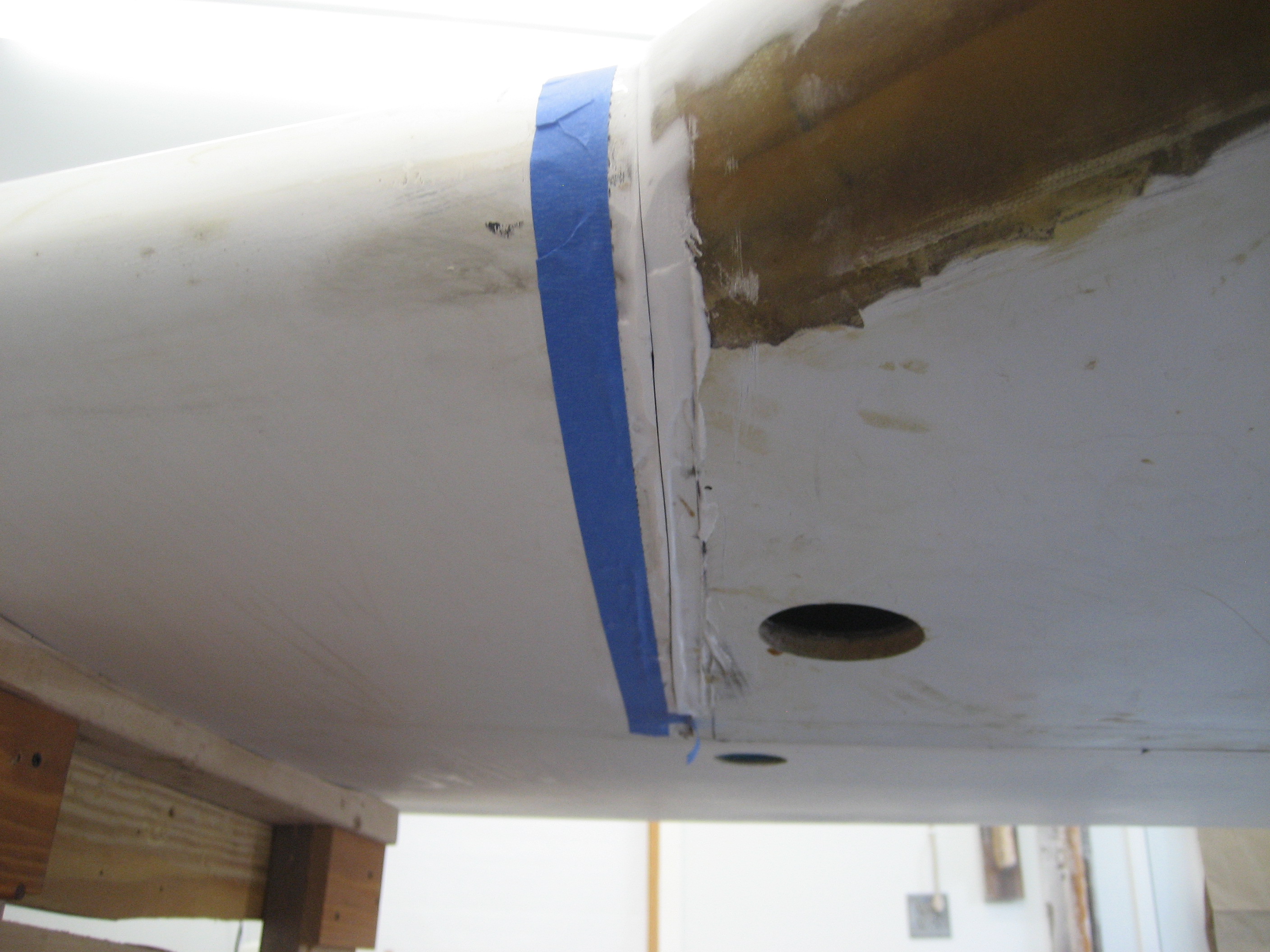
Then put the wing back on (see what I mean about the on-off thing?), applied some duct tape (is there anything that duct tape can’t do?) along the inside of the seam and filled it. Here’s the result.

Then I applied a one BID layup on the inside for strength. After that, it was fill and sand, fill and sand, fill and sand to get the surface of the wing level with the surface of the strake.
Now that the wing is on, have no reason not to finish the repair to the damaged winglet. Here’s the winglet with another layer of filler.
And here it is all finished.

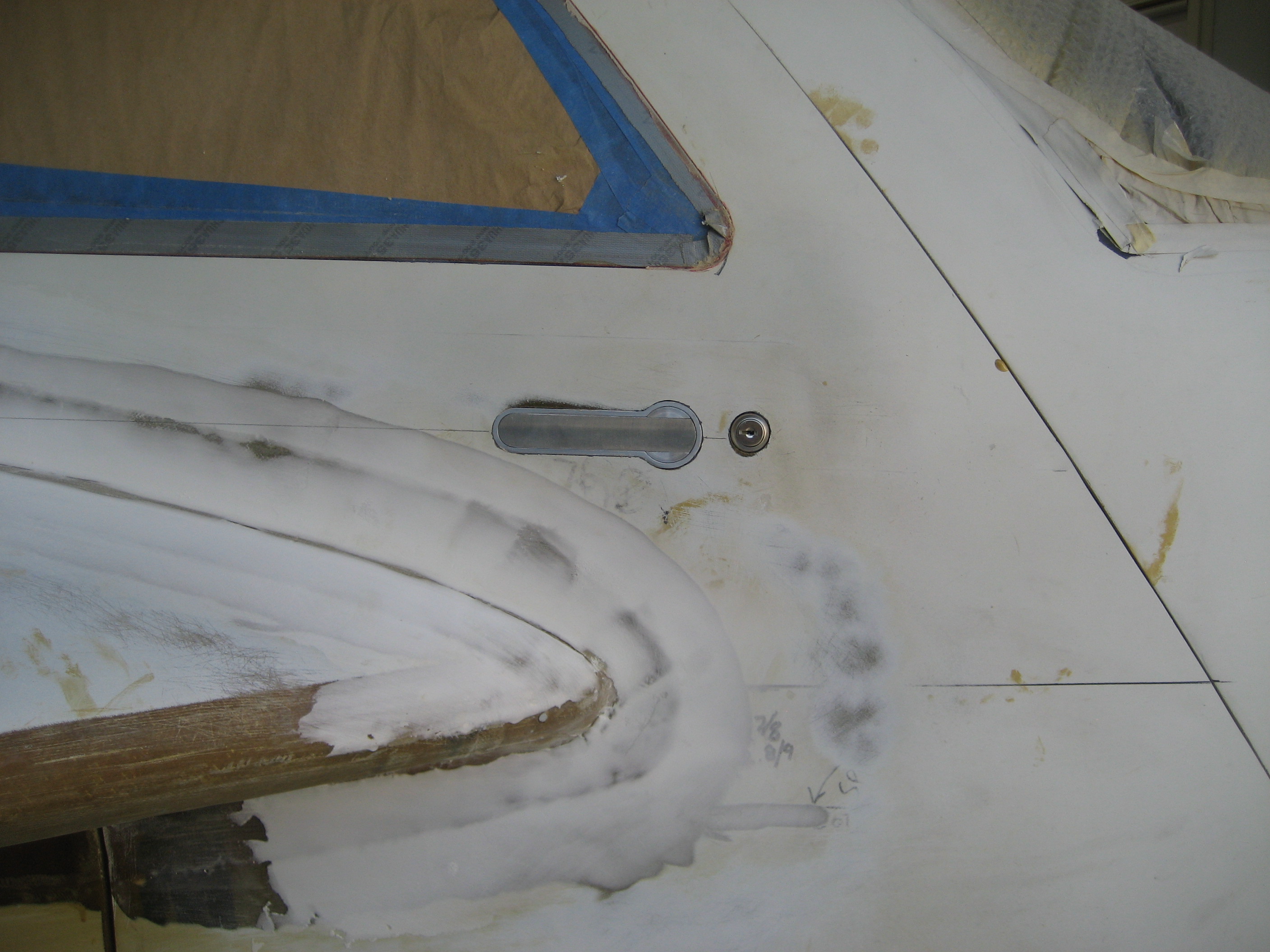
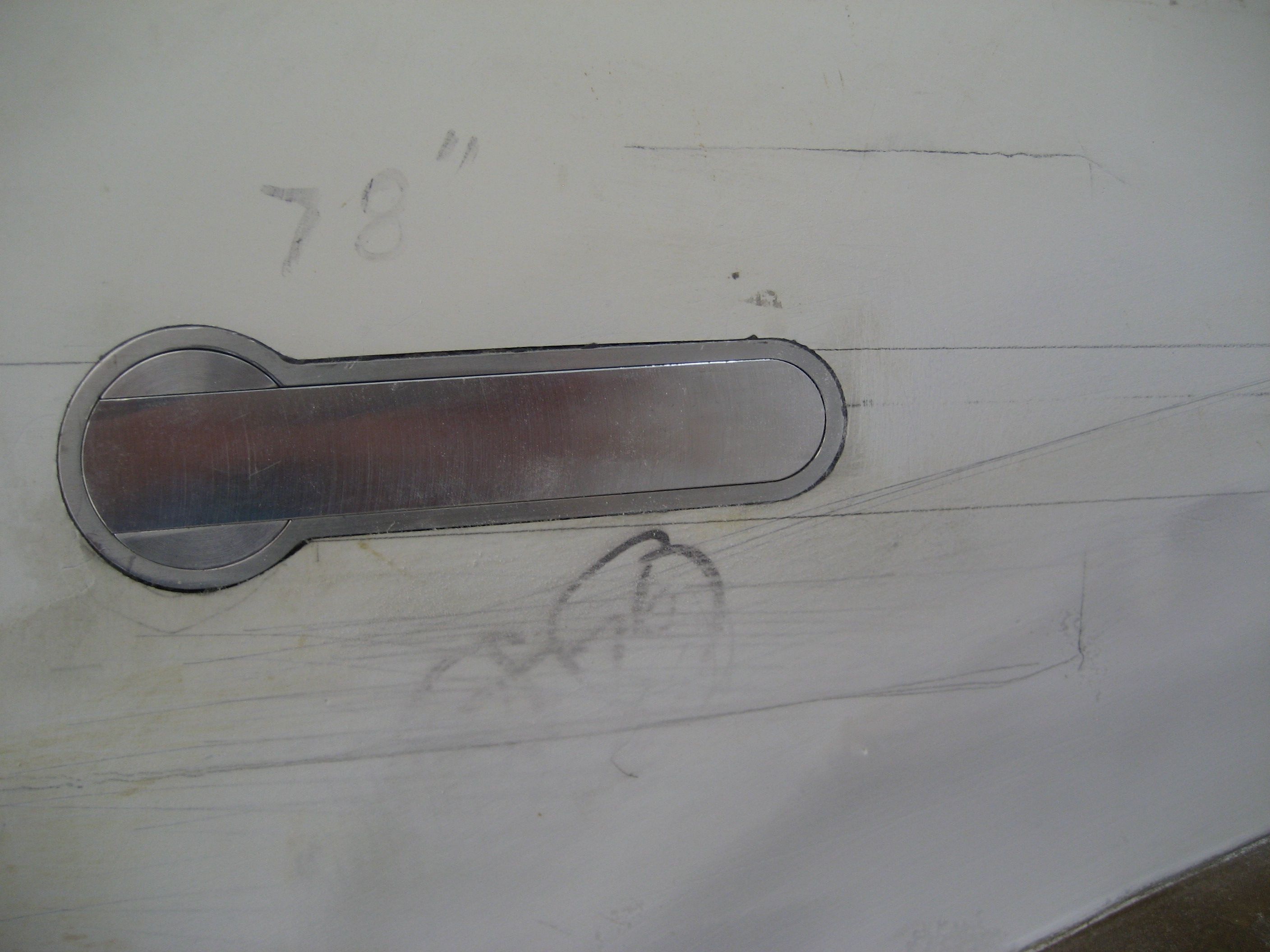
5.3.1 Door Latches
One of the things about the stock Velocity kit that I really don’t like is the door handle. Some people call them “Toilet flush” handles. Here’s why:
That’s how you open the door from the outside.
The inside isn’t much better.
Closed
Open
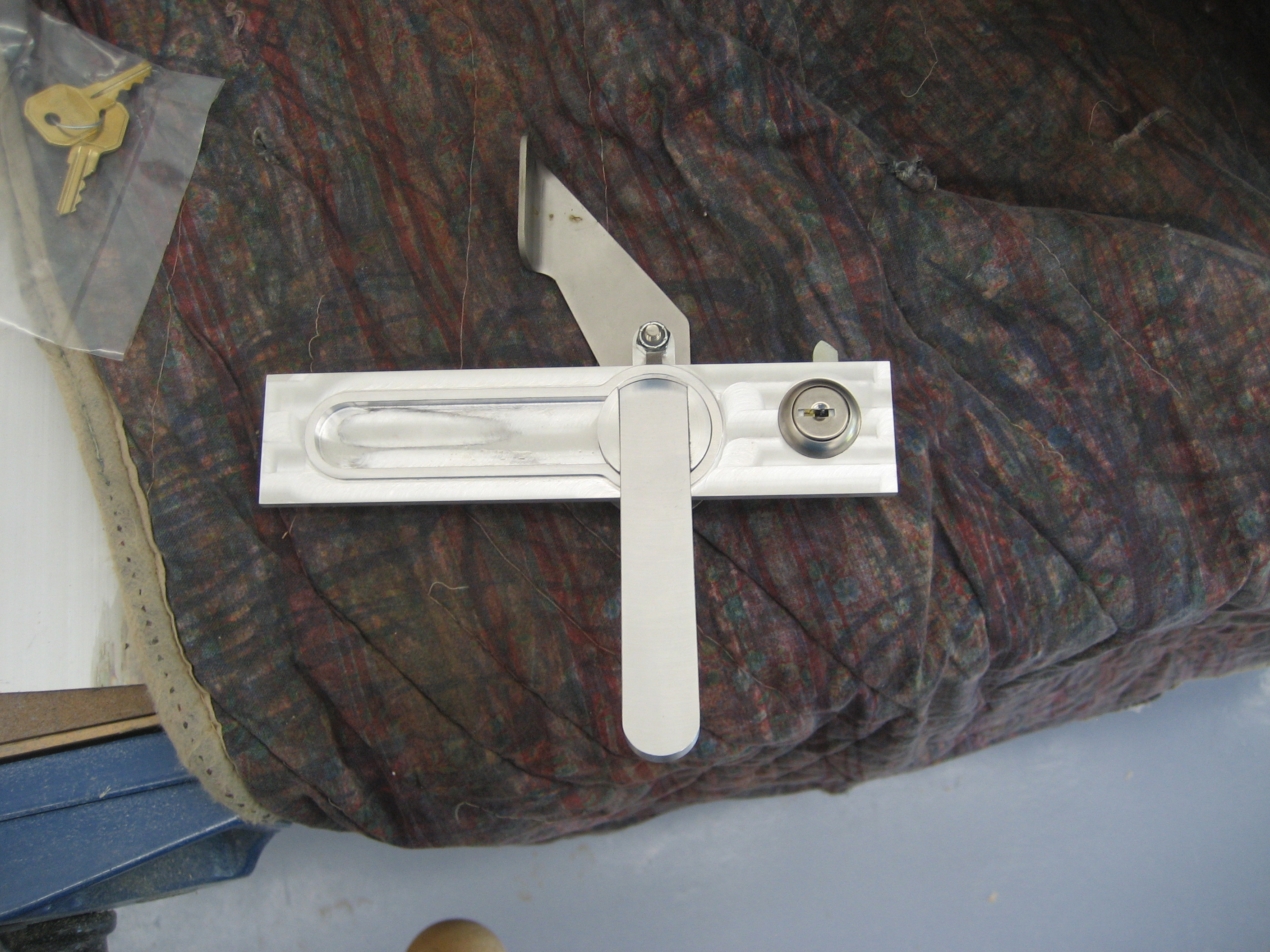
After poking around on the internet, I found some door handles designed for experimental aircraft.

Not only is it flush mounted, but it includes a lock. The handle is spring loaded and pops out to operate.
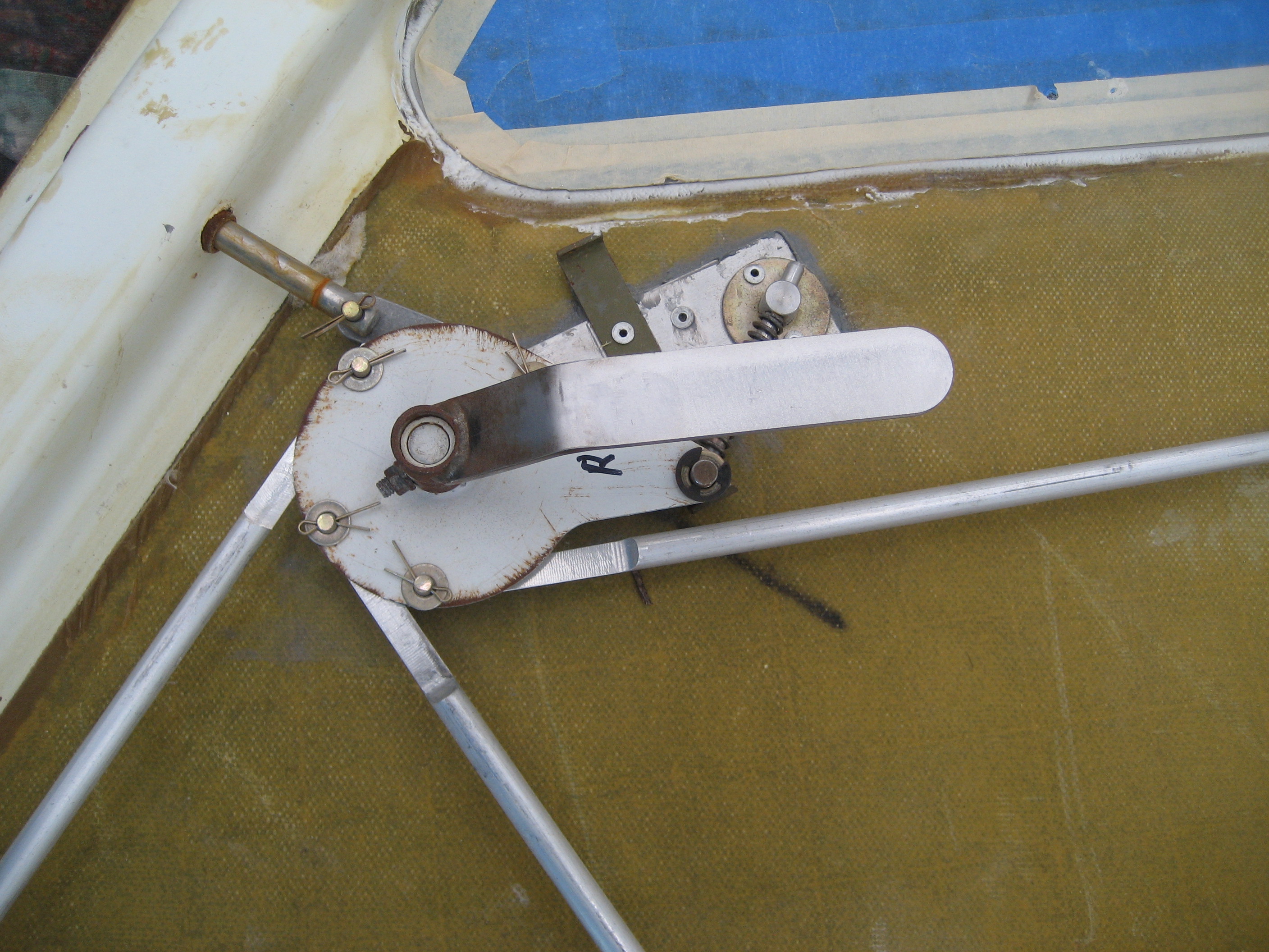
Installing this is going to be easy compared to making it work with the four pins. The person that designed the handle made it for a Van’s RV airplane. They only have two pins (one going forward and the other going towards the rear). In this inside view you can see the center pivot screw and the forward and rear screws that the two links connect to.

With the interior handle removed, you can see the hub (or what the manufacture call the “driver plate”.

So how do you connect four links to a handle designed for two? Improvise!
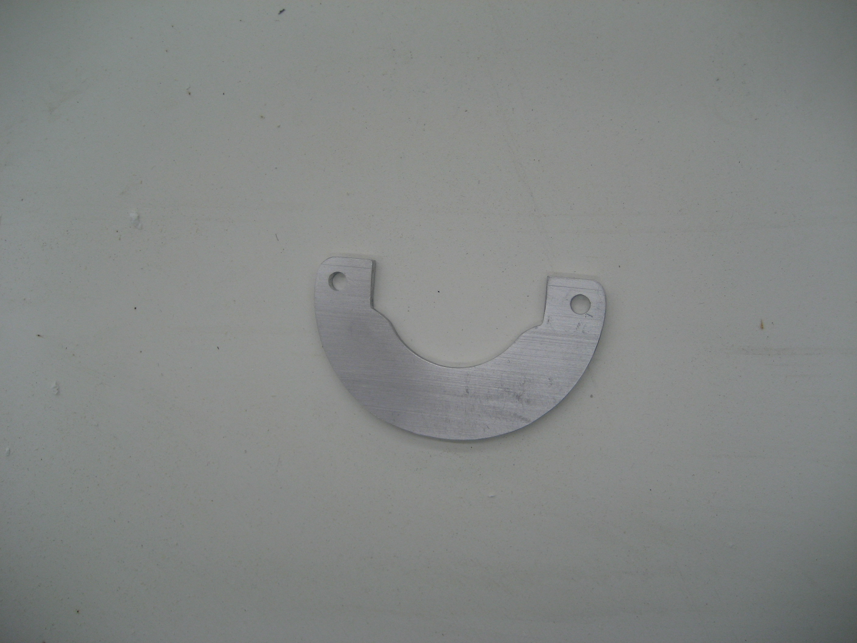
The Velocity door has an upper front and rear pin like the RV’s. Which means I only needed to accommodate the two lower pins. So I made a “Cam Plate” that would tie in to the existing hub. In this picture, I haven’t drilled the two holes for the lower pins yet.
Here it is on the hub.
Once I was certain that I could design the interface between the handle and the pins, I was ready to install it in the door. First, I decided that I would use the hole for the existing handle for the lock of the new handle. Then I drew a level line on the outside of the door centered on that hole. I drilled a pair of holes on that line so I would know where the centerline was on the inside. Then I marked where the handle assembly would be and where the hub would be.

Using Malcolm’s trick, I further identified the line with masking tape.

Then I cut the inner skin and removed the foam leaving only the outer skin.

Next I cut a template so I would know where the cut the outer skin.
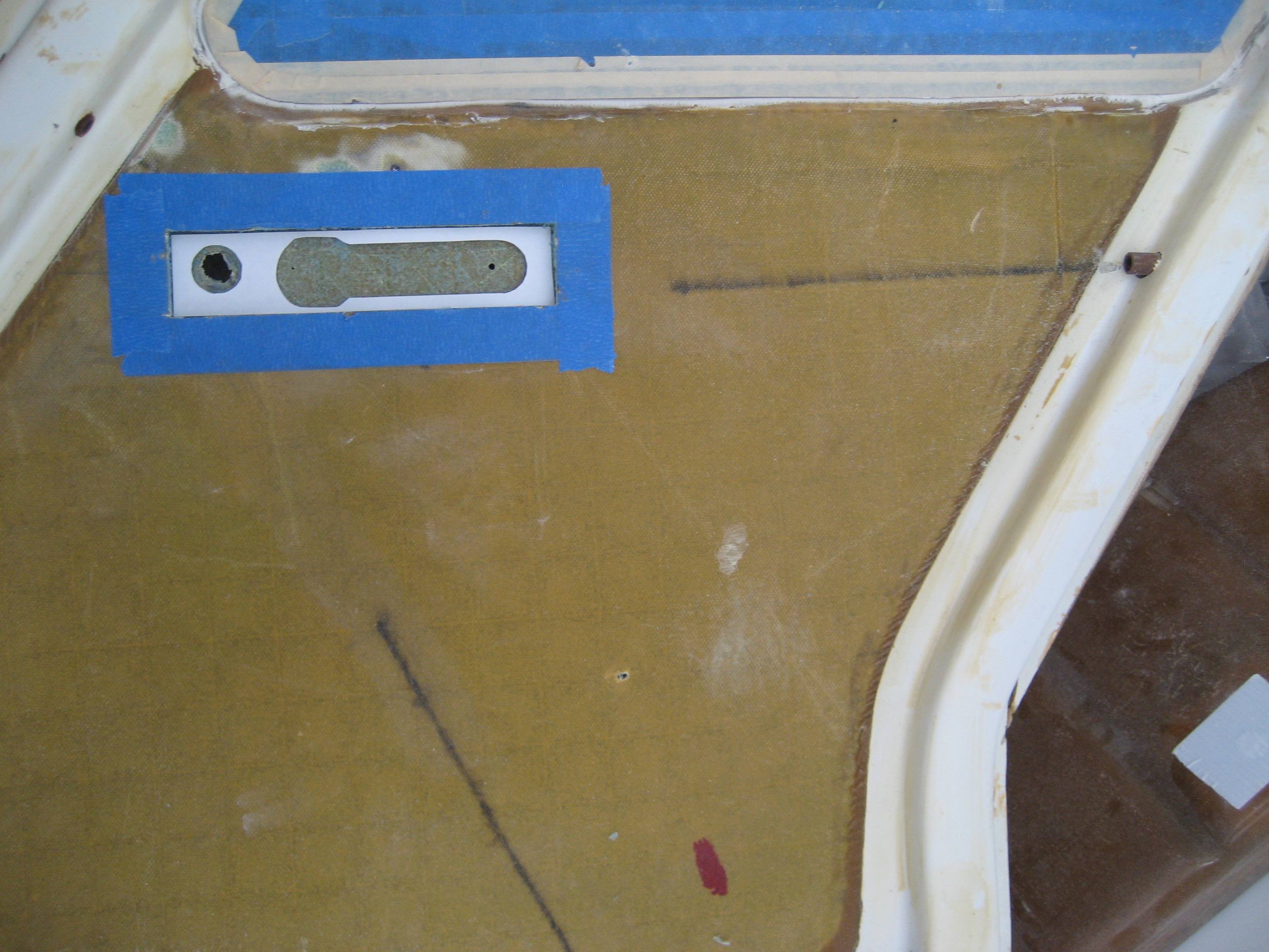
And marked the outer skin.

And cut the opening.
I had to recess the inner skin and foam to allow for the movement of the handle and lock.
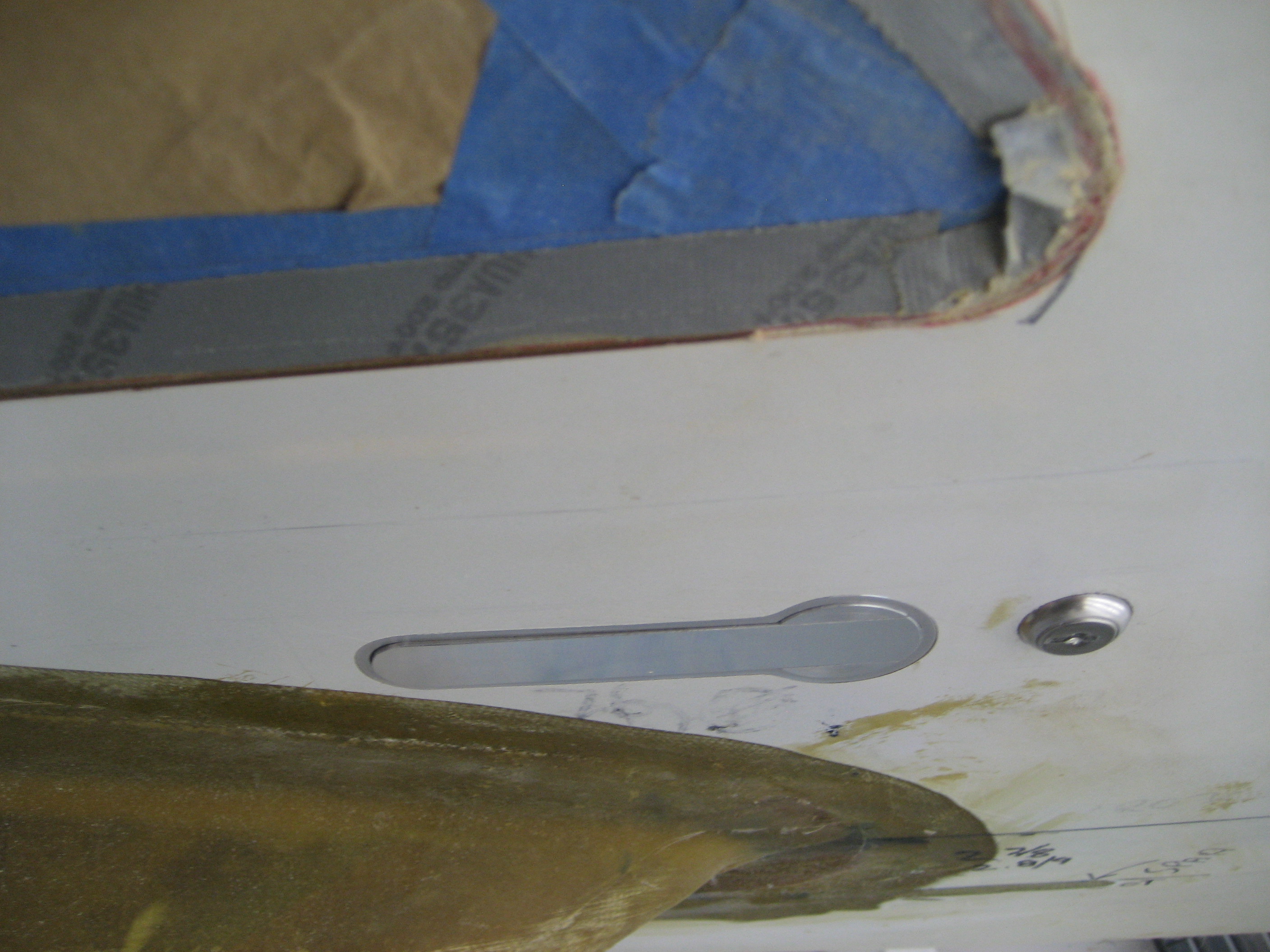
Handle in place (closed).

Handle in place (open)
From the outside

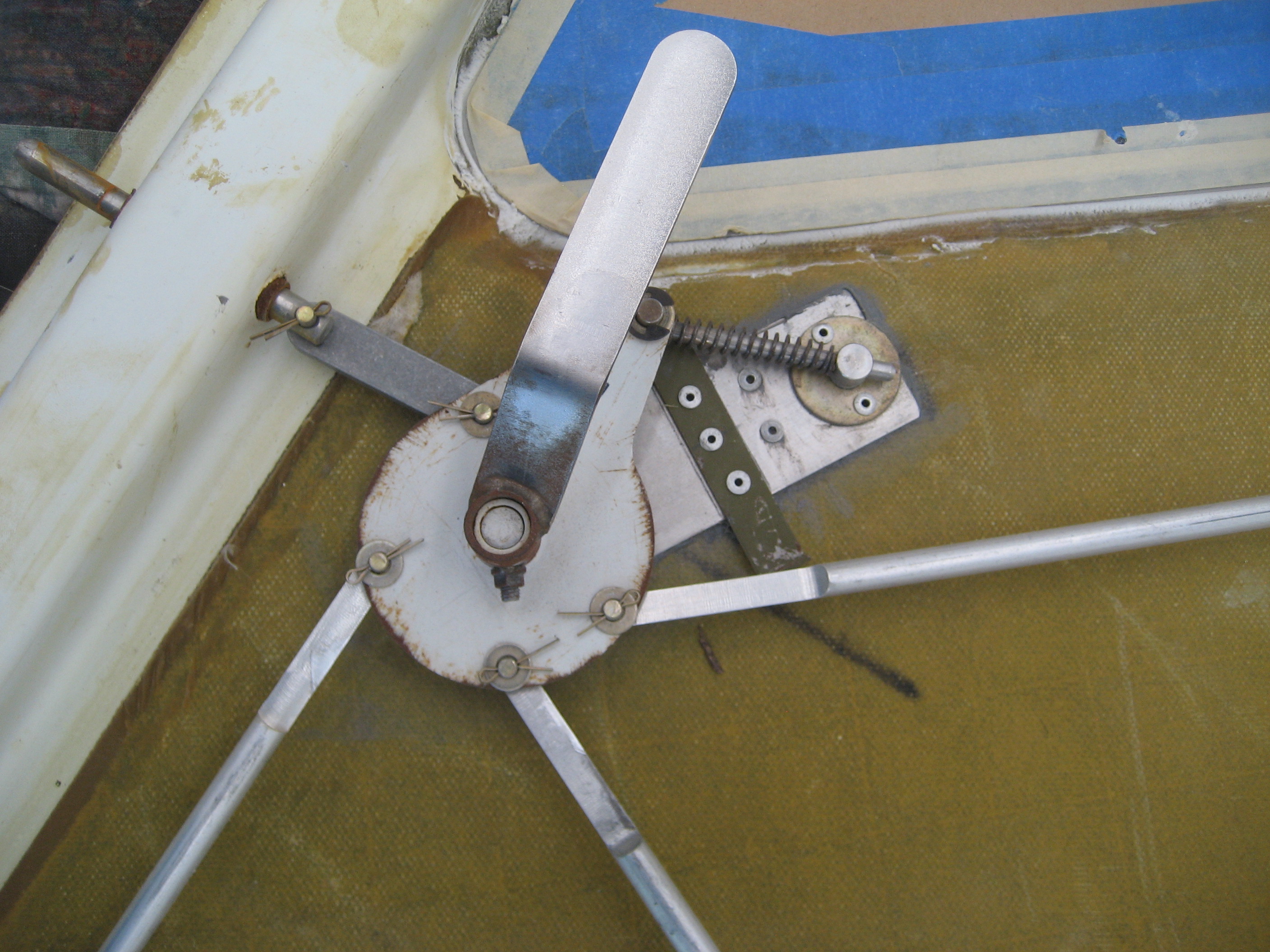
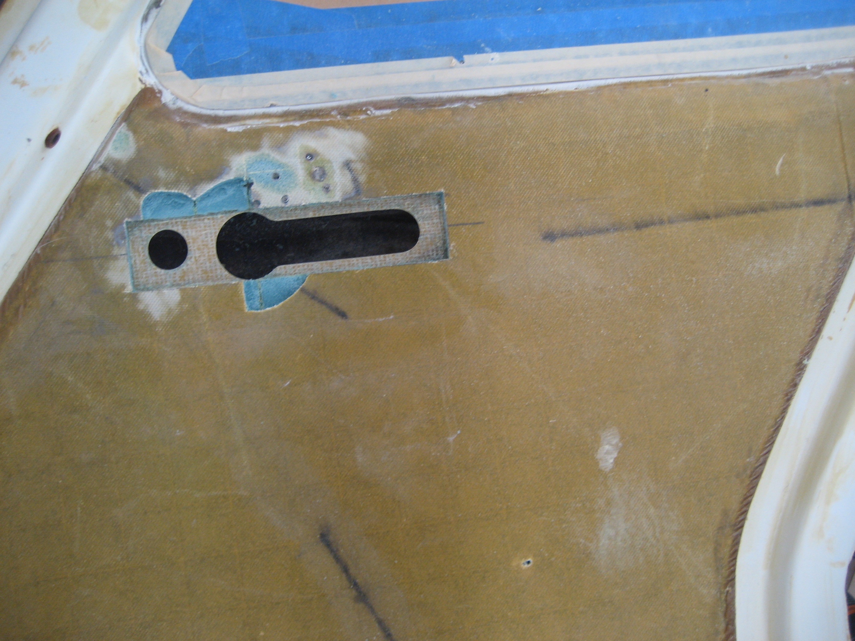
Besides the appearance, another bad thing about the handle is that it’s HARD to operate. Once I looked at it I discovered why.
There are four pins that engage the doorframe to keep the door closed. These pins are attached to shafts that tie in to a cam that the door handle operates. The reason it’s so hard to operate is that when the cam rotates, the shafts move laterally and bind in the sleeves at the door edge. Except for the upper/forward pin. That one uses an intermediate link.


Here’s an animated gif that shows what’s happening.

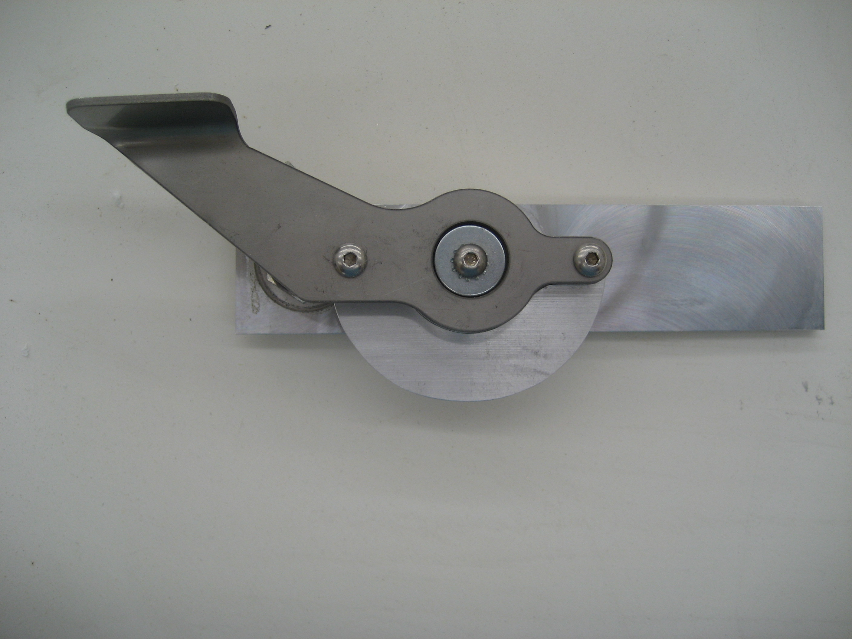
In a previous life, I was a repaired IBM Selectric Typewriters. They’re the typewriters with the golf-ball thing that bangs into the paper to make print. Something like over a thousand moving parts with almost 500 adjustments. It’s a wet dream for Rube Goldberg. So with that background, I was certain that I could build a better mechanism. The key was to keep the pins (and their attaches shaft) movement linear. That would require what I would call an intermediate link. So I make the shafts shorter, mounted a sleeve to maintain the alignment and built eight intermediate links.
Here’s the end result.
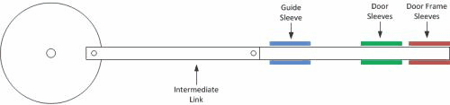
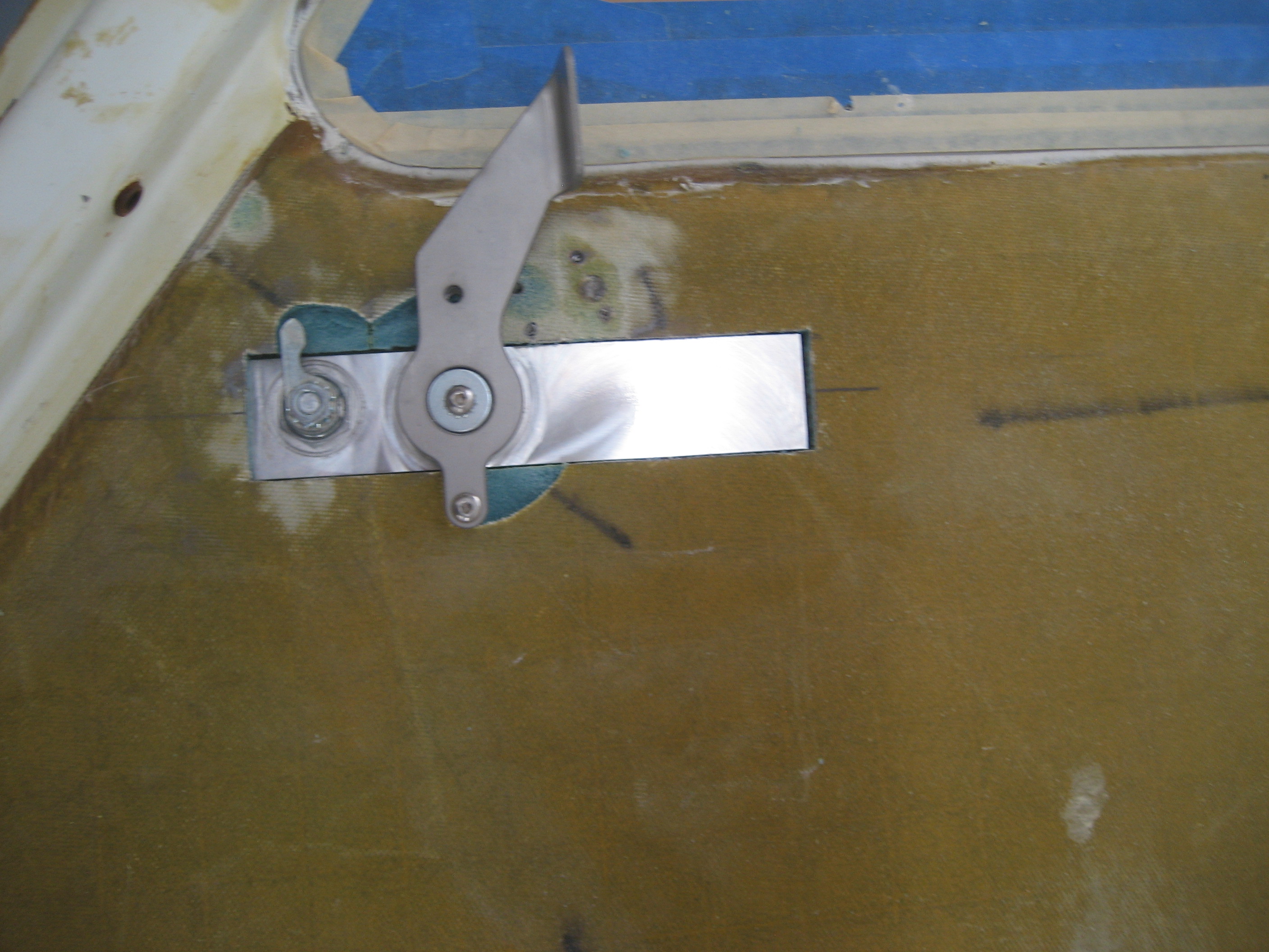
Closed to open


Over-center spring

I located the holes in the cam so that the links would be over-center in the open and closed position. This is to keep the handle from opening (or closing) by itself. I also put a spring on one of the shafts to “load” the mechanism. This will apply pressure keeping the handle in the open or closed position.
Here’s a video (1 MB)
Then I had to remove the receiver sleeves in the door frame because they were set for the positioning of the old pins. Once I got them removed, I put the doors in just to give myself a pat on the back.
Right door.
Left door.

Uh-oh. Something doesn’t look right on the right door. So let’s play “Find Waldo” and see if you can tell what’s not… good.
I’ll wait.
Did you find it?
Here’s a close up.
It’s not level! I put these marks on the outside but all the cutting is done on the inside. Somehow, I put the door handle in and didn’t check the outside alignment. I thought about for about 5 minutes before deciding to remove the handle to correct it. I know it’s only off by about 1/8″. But there’s the slippery slope. If you let this slide, it makes it easier to let the next thing go and pretty soon you’re flying something that’s held together with duct tape and bailing wire. Besides, what if I put a stripe down the side of the fuselage and it’s right next to the handle? Then it’s really stick out!
Removing the handle, enlarging the opening and epoxying the handle back in only took about two hours so it wasn’t a huge issue.
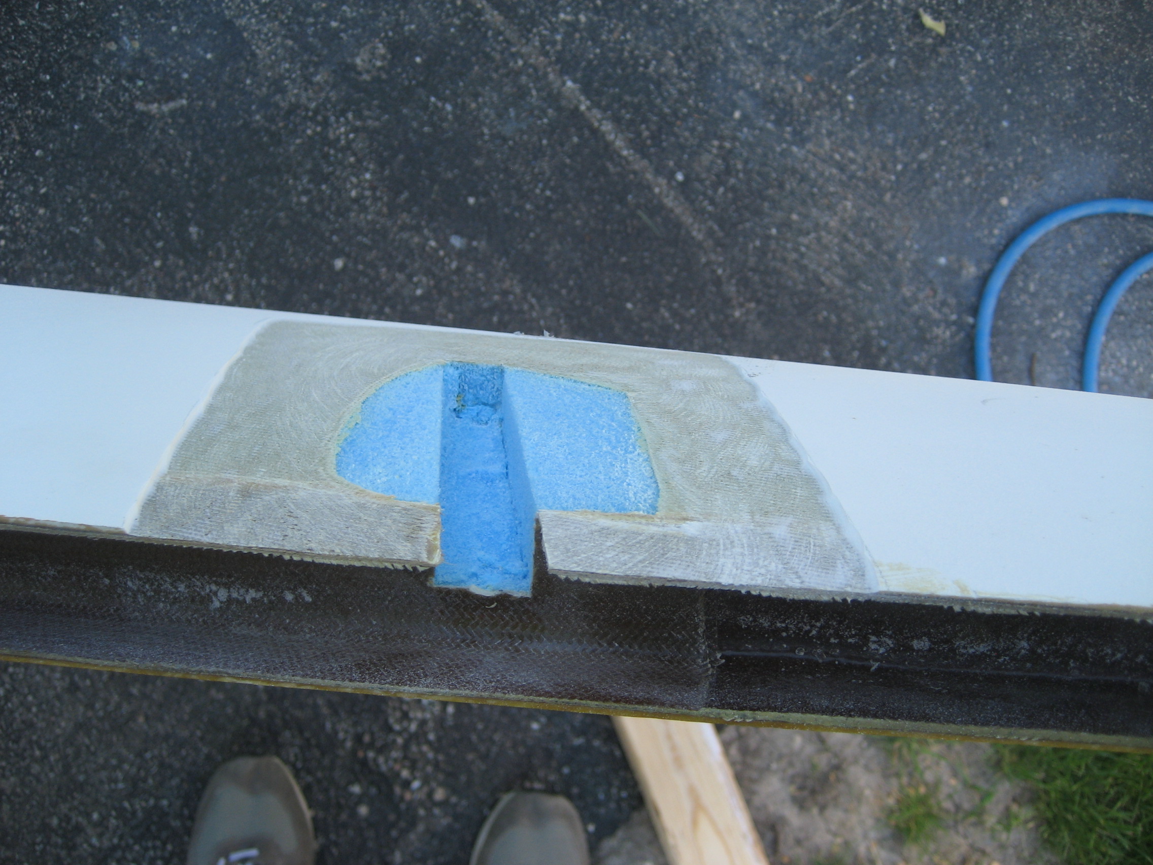
14.1.2 Tie Downs
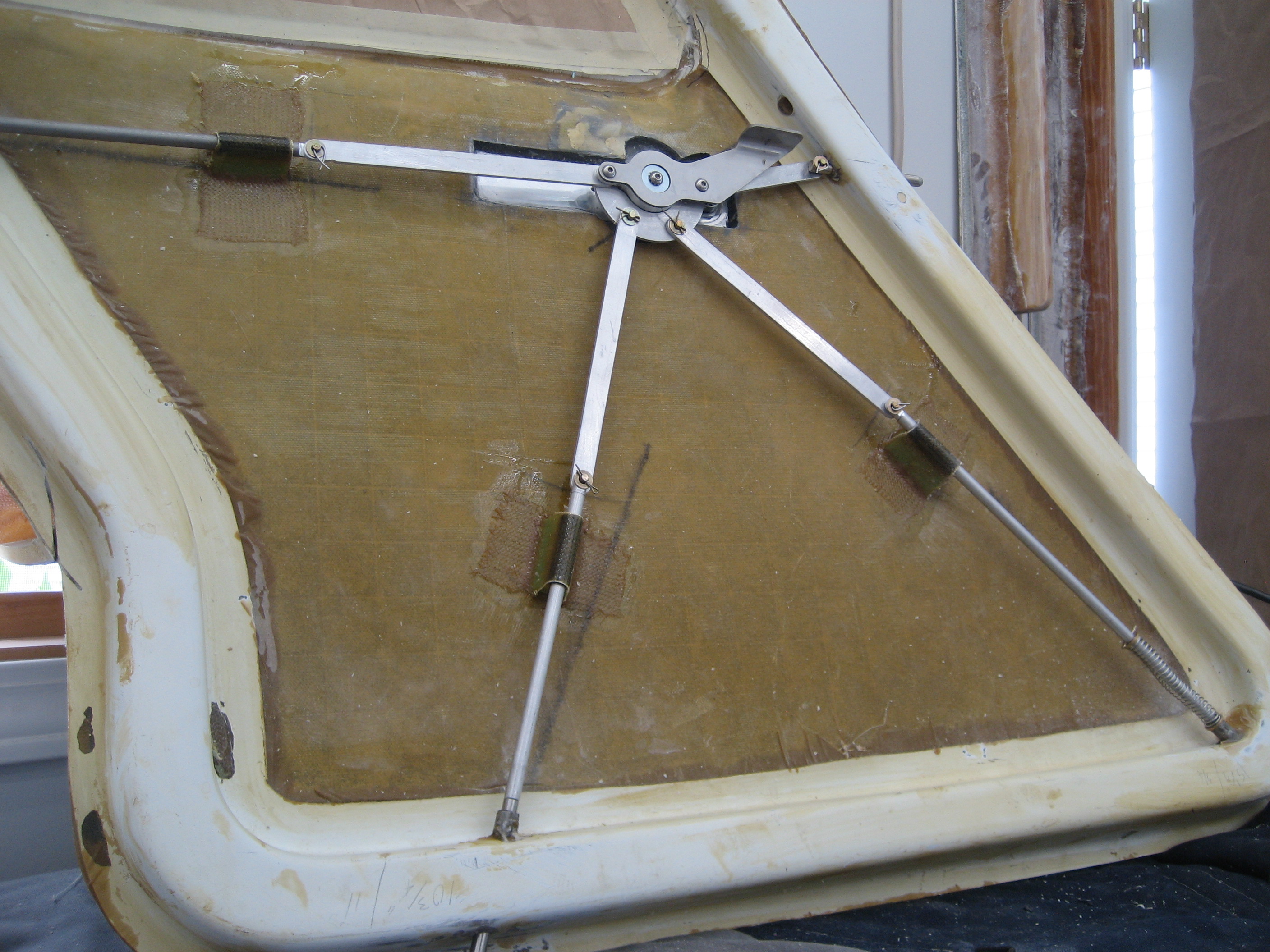
The last item is the main wing tie downs. When you park your plane for any length of time, you need to tie it down. The factory supplies a pair of screw eyes that you bolt to the bottom of the ends of the center spar. But that just looks bad. Two big honkin’ rings hanging off the bottom of the wing. So builders have gone with a pivoting ring that’s spring loaded so that it’s recessed. This is the same type that’s used on my Cessna. I, however, went with plan “C”. A retractable ring that uses gravity instead of a spring. Springs fail, gravity doesn’t.
Here’s the tie-down ring when not in use.
When the wing is on, only the little tip will be sticking out. Snap it with your finger and pull it down and the ring is exposed.
With no rope through the hole, gravity pulls it back to the recessed position.