5.2 Correcting Door Fit

This entry is part 11 of 16 in the series 05 - Doors / Windows

Now it’s time for the doors. Once again I didn’t get pictures but I’ll try and explain. The doors DON’T FIT. Well, they do, but not very well.

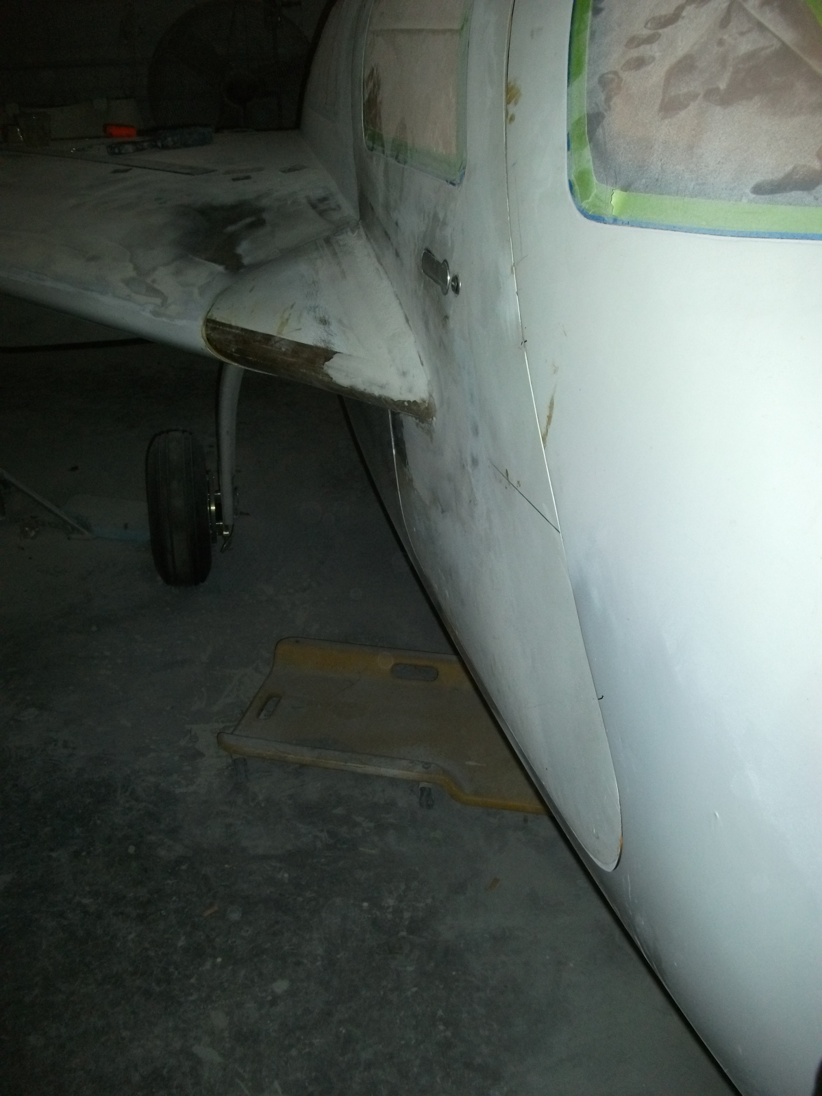
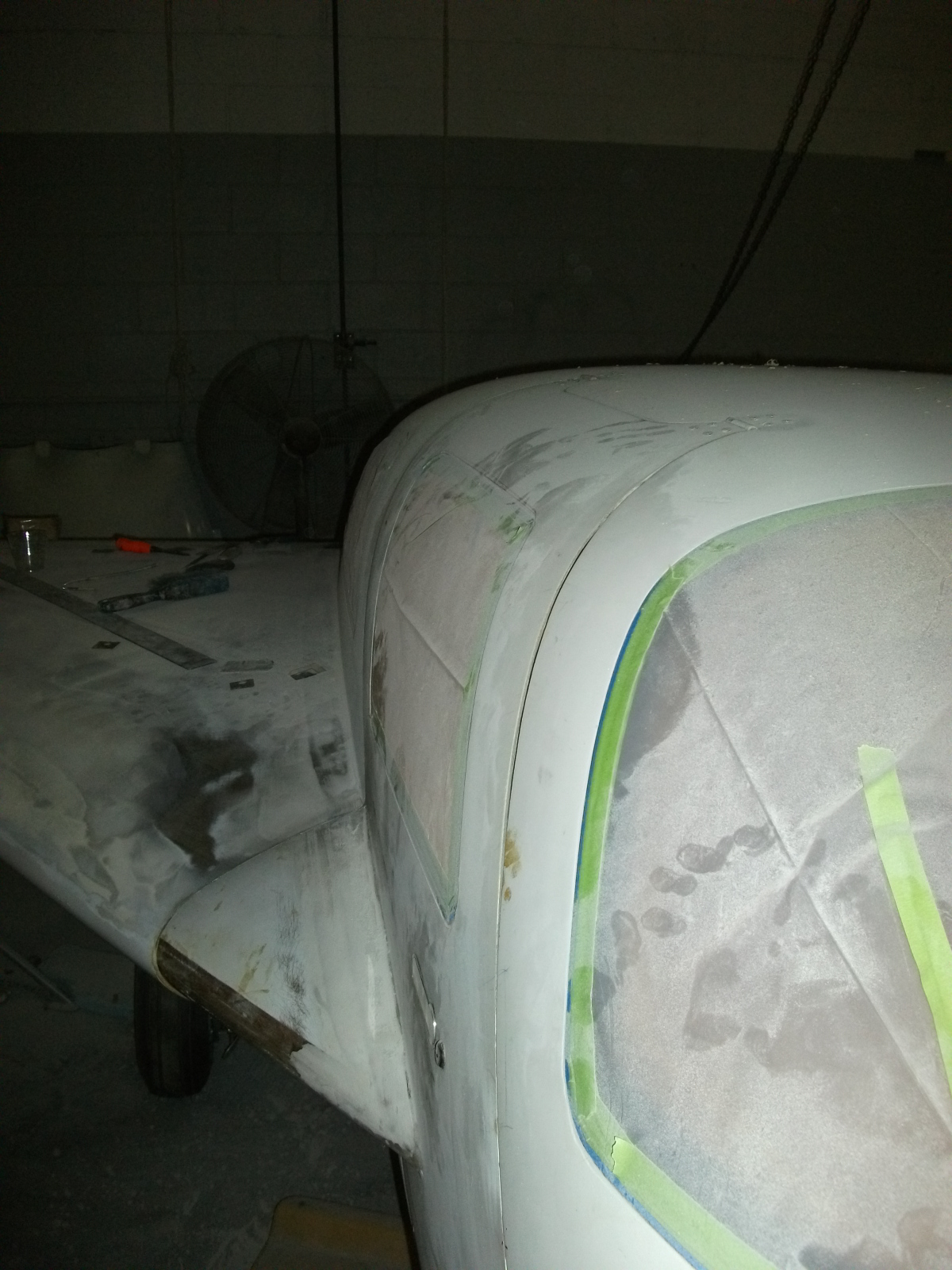
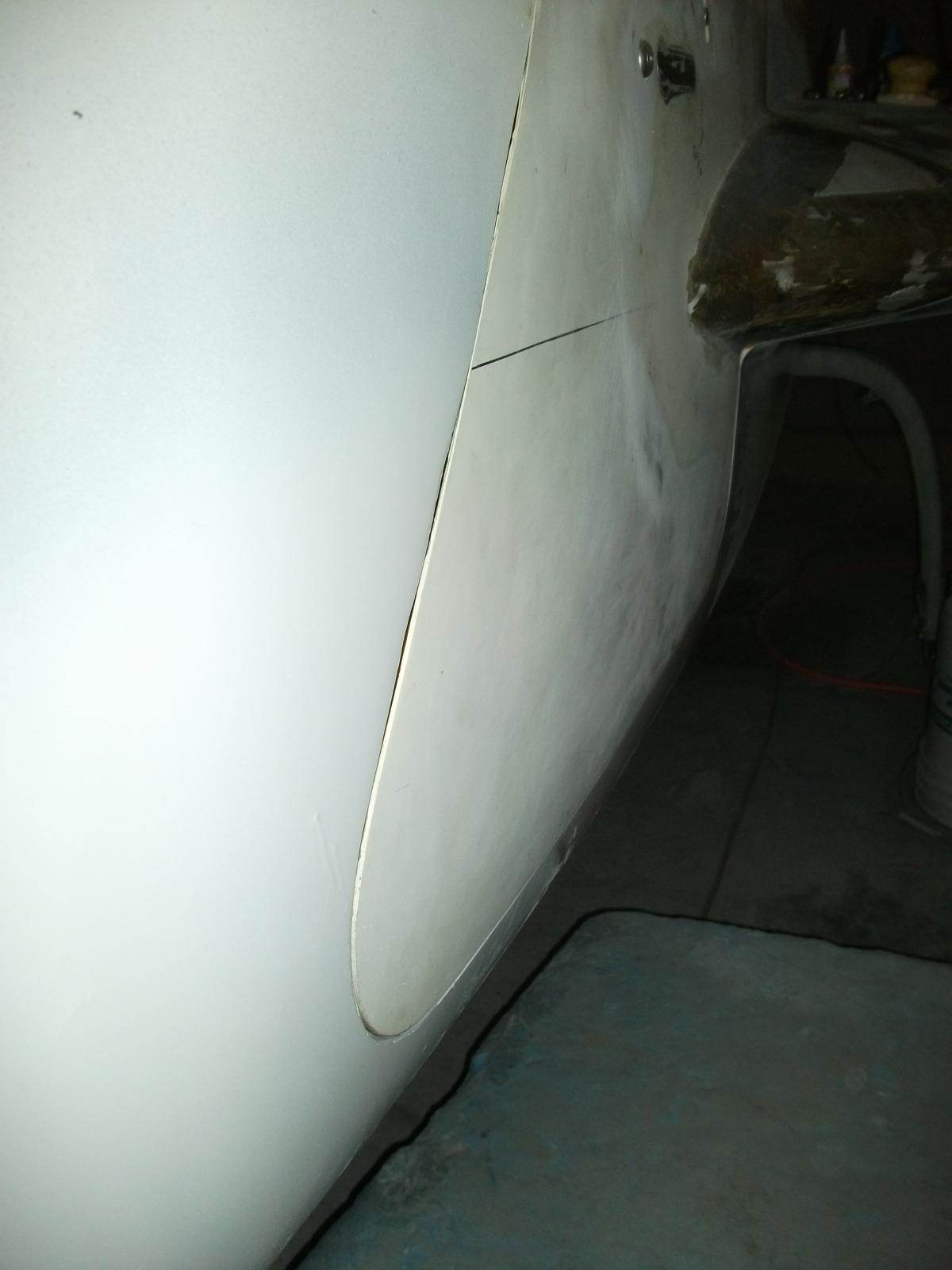
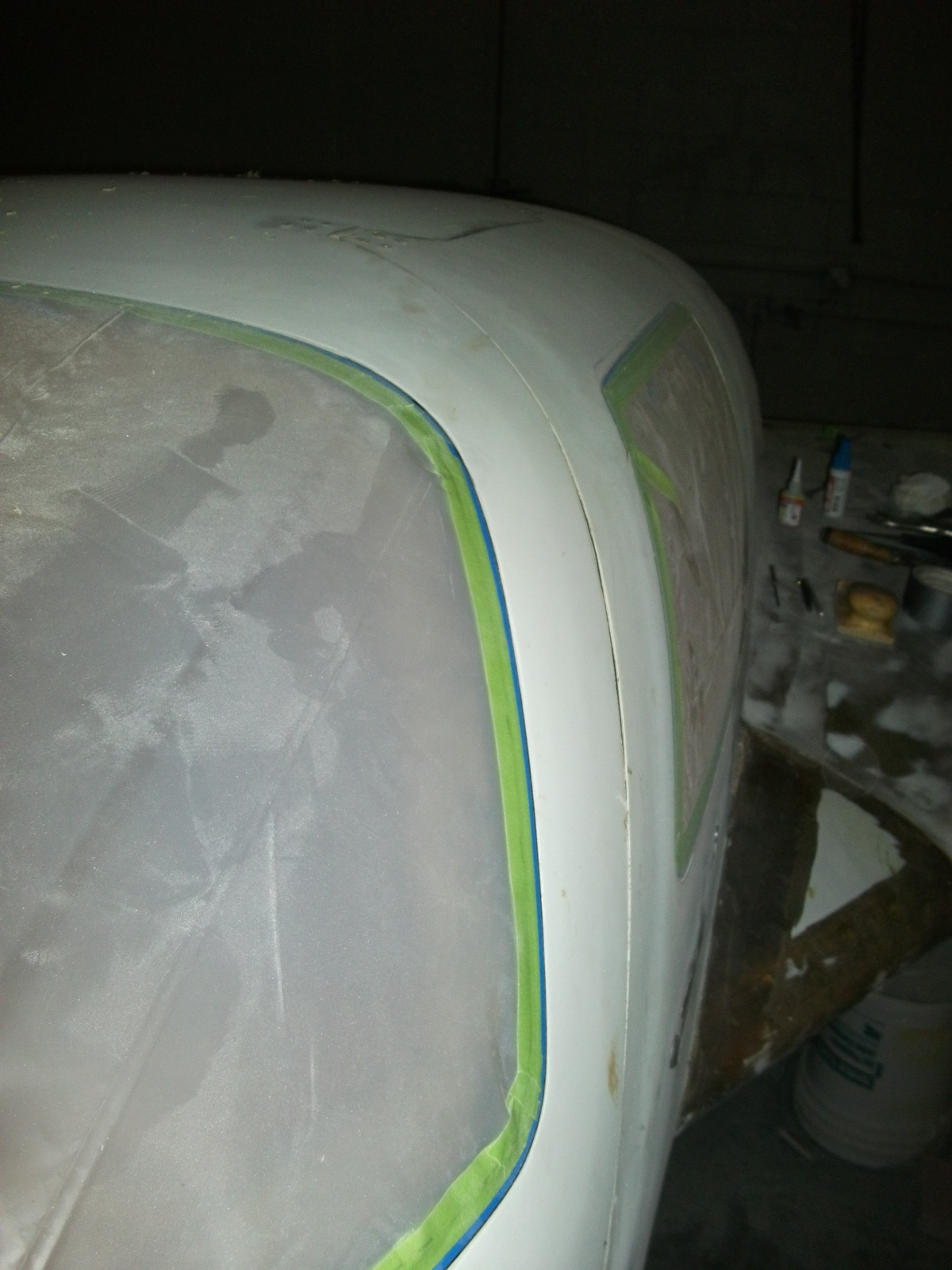
This is a picture where I’ve indicated the fit problems. It sticks up at the top rear. It sticks out at the bottom rear and it’s inset at the bottom front. Now one fix is filler. LOTS of filler. But there’s two problems with that: 1) You’ve got to try and fair in all that filler so it looks right and 2) that filler has weight. And every pound of filler is a pound of passenger or baggage or fuel that you can’t carry.
2010-11-01A-1

I had discovered this fit problem earlier but wasn’t sure how I was going to fix it. Malcolm to the rescue. 🙂

Here’s what we did. Where the hinge mounts at the top rear of the door, we added a two triax layup (the front got a 1 BID layup too). This moved the rear of the door down. The twist at the bottom will be taken care of by shimming the door so the bottom is flush and gently heating the door with halogen lights. After about 24 hours, the door will be “warped” into alignment.

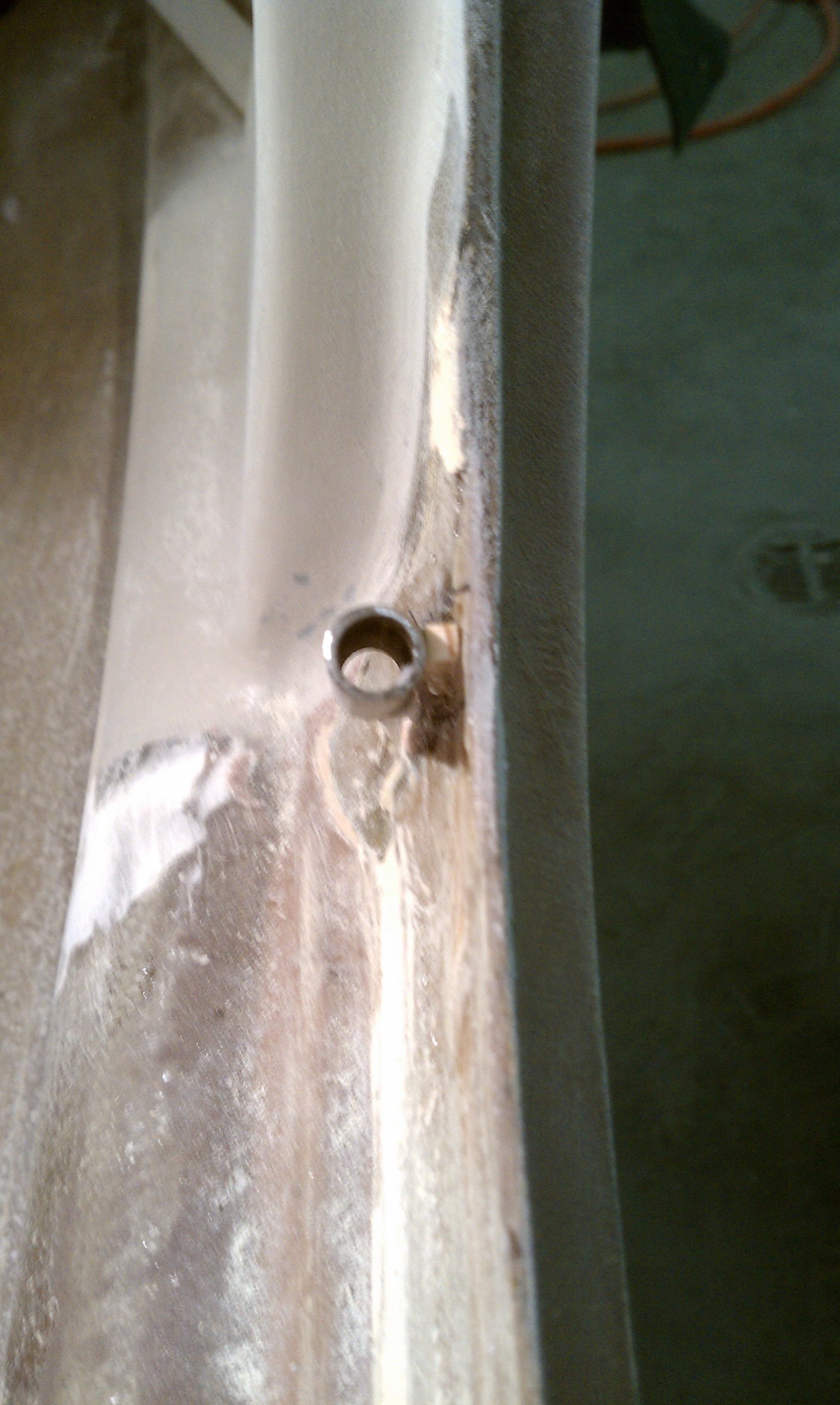
Once the hinge pads were cured, we had to drill new holes for the hinges. This creates a bit of a challenge because if the holes are not in EXACTLY the right place, the door won’t fit properly. My solution was to use a VIXX bit. While I was at Home Depot looking for one (Which sucks because I’ve got a collection of them at home), Malcolm called with an idea. He had me buy 4 set screws with the same thread as the holes in the hinge (I think there were 10-32). When I got back, he drilled out the center of the set screws. So I climbed inside and the he held the door in position. I put two set screws in each hinge. When the door was in exactly the right position, I drilled through the center of the set screws into the fuselage. Then I removed the set screws, flipped the hinges out of the way and enlarged the holes to their final size.  I held the hinges in place and Malcolm screwed the hinges in place from the outside. Then I did the remaining two holes in each hinge. When we were done, the top of the door fit almost perfectly! 

Then is was time to do the other door. And that’s when I got a surprise. While we were working on the door, it’s sometimes necessary to bang on it to get the door in position. While I was inside and Malcolm was “encouraging” the door into position, I became weightless! Relative to the inside of the plane, that is. The main landing gear is held in the “down and locked” position with an over-center stop and latch. The nose gear has an overcenter stop and a gas strut. What I’ve always done is to put a wire tie around the nose gear arm and the over-center stop… Just in case. Well, in all the moving things around, that got over looked. While Malcolm was banging on the door, the nose gear actuator arm bounced and got… under-center. At which point the nose gear retracted. And the nose went down.

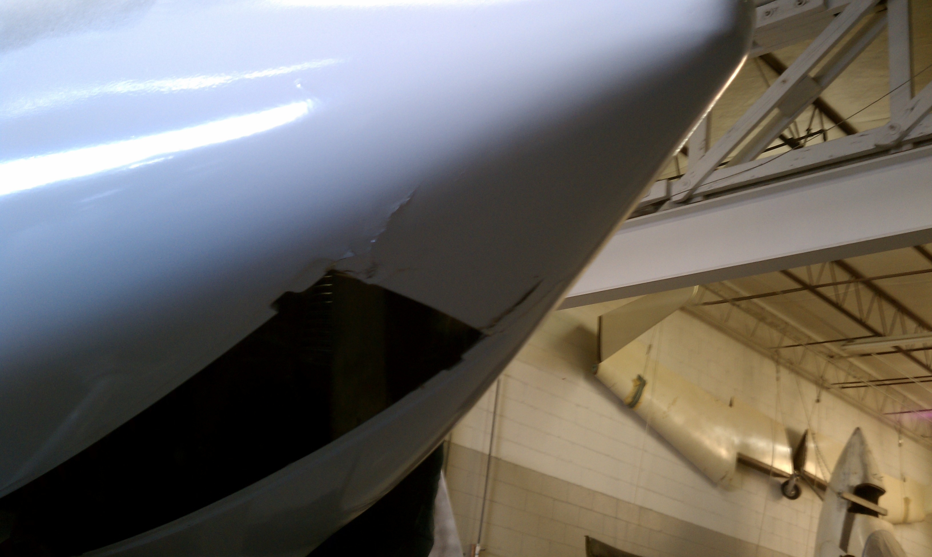
I climbed out, we lifted the nose off the ground and put a sawhorse under the nose and then looked at the damage.
2010-11-02B

During previous maneuvering, the nose wheel got rotated 180 degrees from it’s normal position. This turned out to be a good thing. When the nose gear came up, the tire hit the bottom of the fuselage and then broke through. This slowed the descent so that when the fuselage came in contact with the floor farther back, there was no damage. These cracks up here aren’t in a structural area and are easily fixed.

So from now on, either there will be a wire-tie on the nose gear arm and over-center stop or there’ll be a support under the nose.

Once the door hinges were finished, lights were placed on the inside warming the door while on the outside a heavy shot bag pushes the door into position.

  2010-11-29C2010-11-29B

14.2.1 Finishing Upper Airplane

This entry is part 27 of 38 in the series 14 - Final Assembly / FInishing

When I was working on the strake-wing joint on the top, I did the co-pilot (right) wing first. I concentrated on the area where the wing meets the strake. When I did the Pilot (left) side, I discovered that there was a “valley” that ran the length of the wing. I spent a LONG time filling and fairing in that wing. I was going to fix the right wing later.

Well, it’s later.

First we checked the left wing. I was pleased when Malcolm declared it good.  But even so, we hit the entire wing with sanding boards and got it more better. 🙂

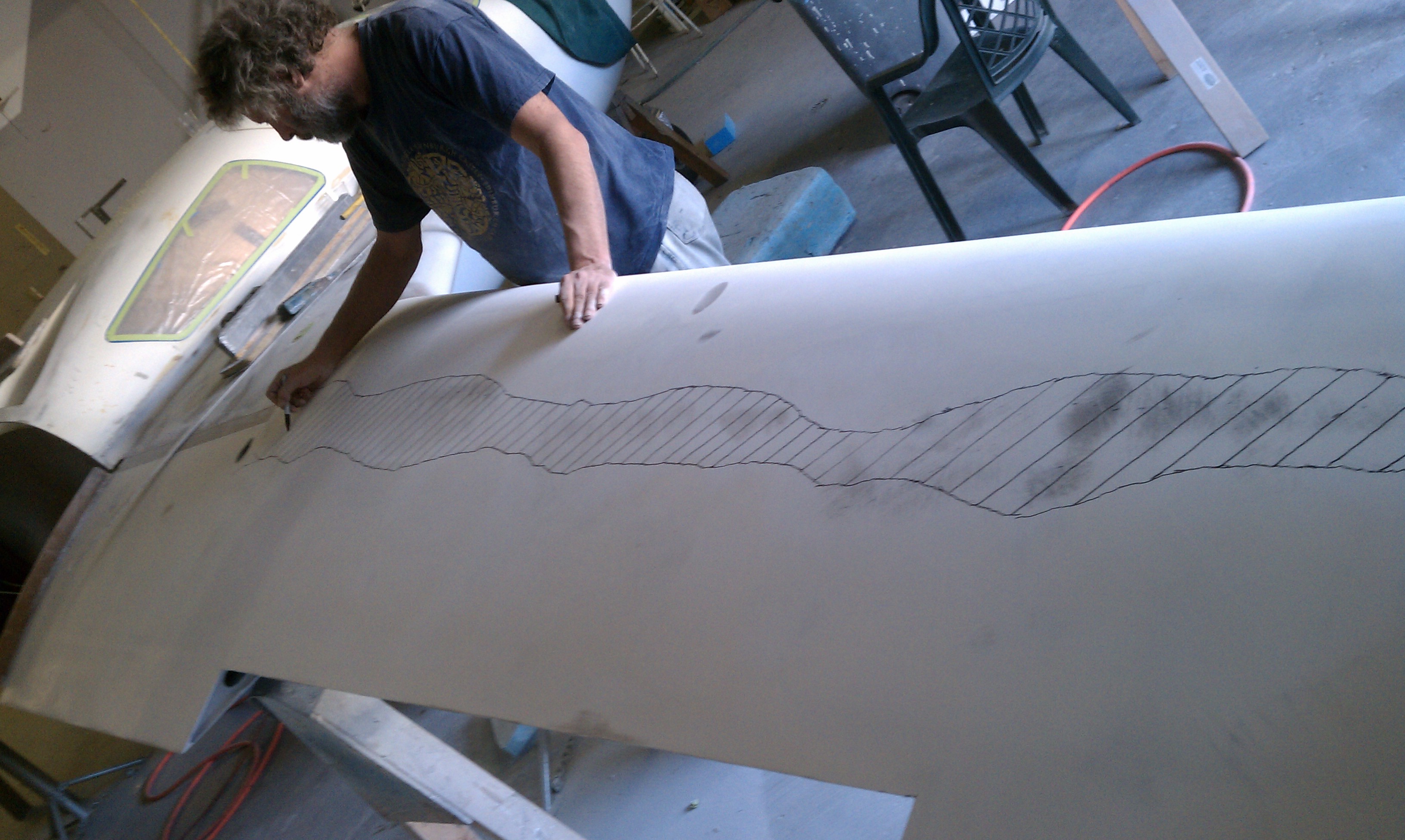
Then is was time for the other wing. We spent the better part of a day sanding off all the excess filler. Then we “splined” the wing. Where the spline doesn’t touch the wing is a low spot. You mark those spots and then move the spline over and repeat. And repeat, and repeat and repeat. The result gives you and idea where the low spot is that needs fill.
2010-11-02D

Next comes fill and sand. At least it only needs to be done on one wing.

13.3.4 Overhead Switch Panel

This entry is part 55 of 67 in the series 13 - Electrical / Instruments

When I’m not in SC, there are still things that I can do at home. Electrical system planning is one. I’ve already designed the courtesy lights. Now I’m working on the Overhead Switch Panel (OSP). The OSP is part of the A-Beam (it goes across the inside of the roof between the A-Pillars) and can have switches or indicator lights. There are many approaches to this. For example:

Andy Millin’s OSP
amillinOSP
Terry Miles’ OSP
2009-12-18 1319 IMG_9598
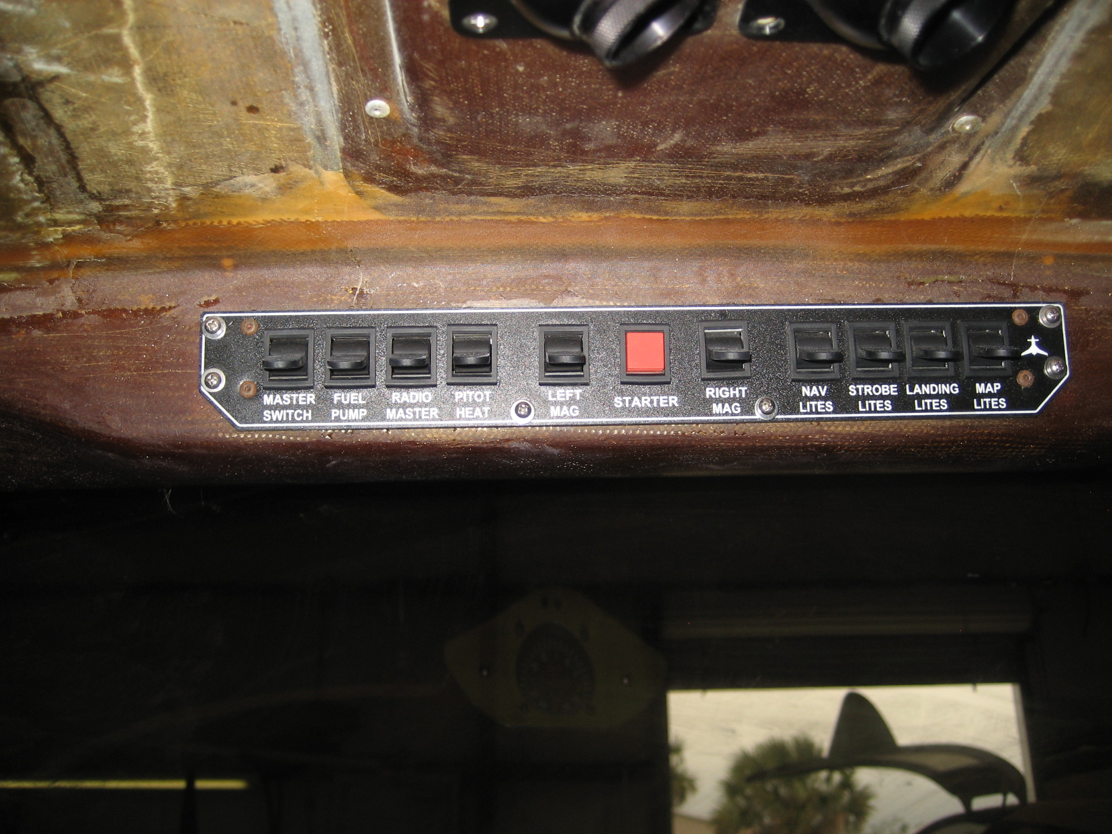
 I don’t remember who’s this one is
OH1

 Rich Guerra’s OSP
rguerraOSP
 Fred’s OSP
2008-01-18 1225 IMG_5774
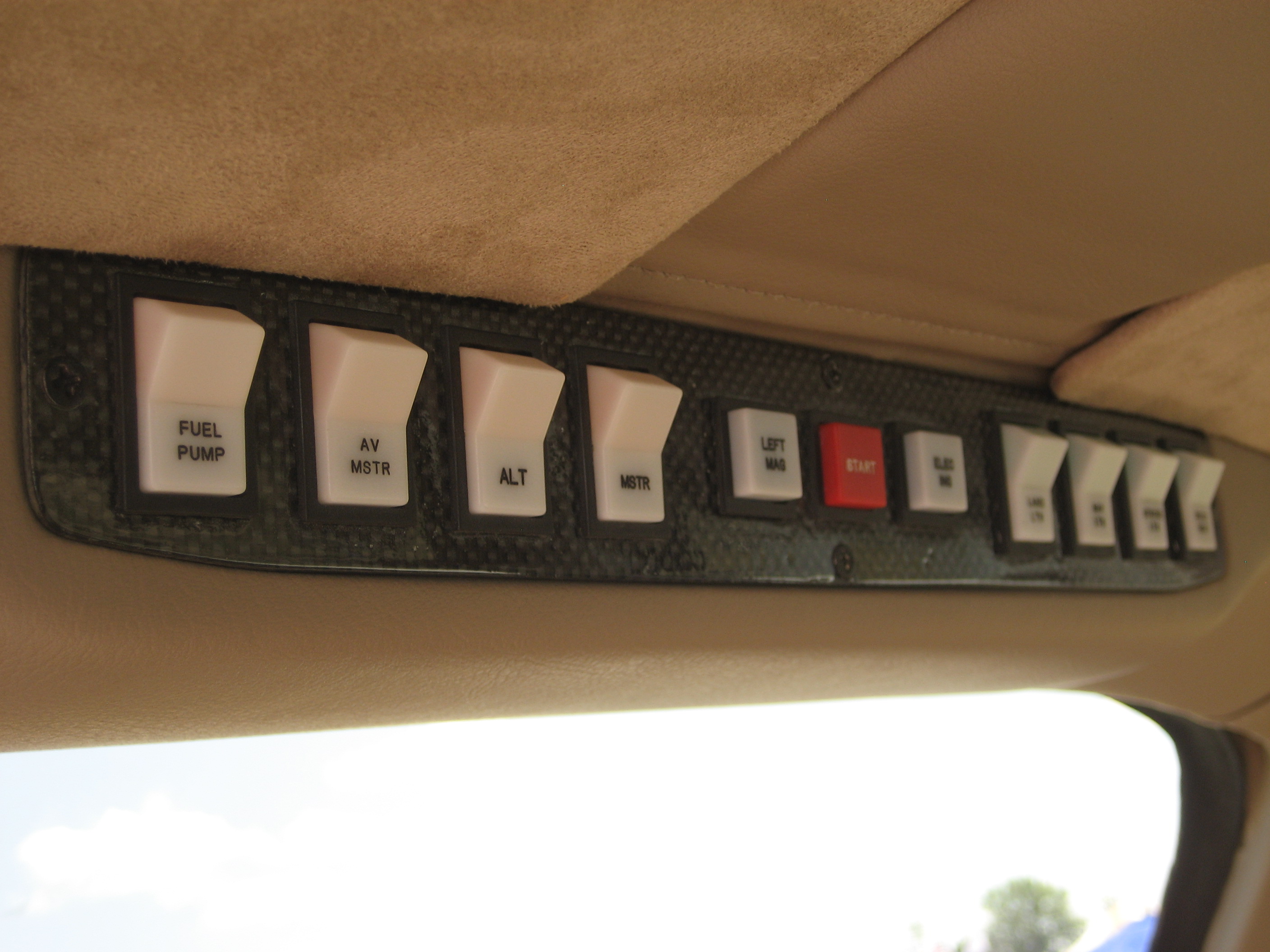
 The Factory Demo Plane
IMG_9104

Now Andy has some really sweet lighted and engraved rocker switches! But because My A-Beam has a very low profile, I don’t have enough room for the rocker switches that Andy is using. So I decided to go with traditional toggle switches.

There are a couple issues to be dealt with on this panel.

  1. It’s real easy to reach for one switch and hit some turbulence and end up turning something on or off that you didn’t mean to.
  2. Most of the time when you’re flying, you are either looking outside or at your main instrument panel. If you’re flying IFR (Instrument Flight Rules) then you’re looking only at your instrument panel.

Switching your view from outside (straight ahead) to the main panel isn’t that difficult. You move your eyes a little and refocus. We do that every day when we drive. But looking at the OSP will possibily require moving your head and refocusing your eyes to something less than 12 inches away. This can be very distracting. So it would be nice to not have to ever look at the OSP when flying.

Here’s how I’m going to deal with these.

  1. I’m going to install switch guards on all the switches. That way, it will be almost impossible to “bump” into an adjacent switch. They also give your hand something to rest on when you’re activating a switch.
  2. I will also only use the switches for functions needed during engine start and engine shutdown. This way, I’ll never have to even think about these switches during flight.
  3. The sequence on activating the switches will be left-to-right for engine start and right-to-left for engine shutdown.

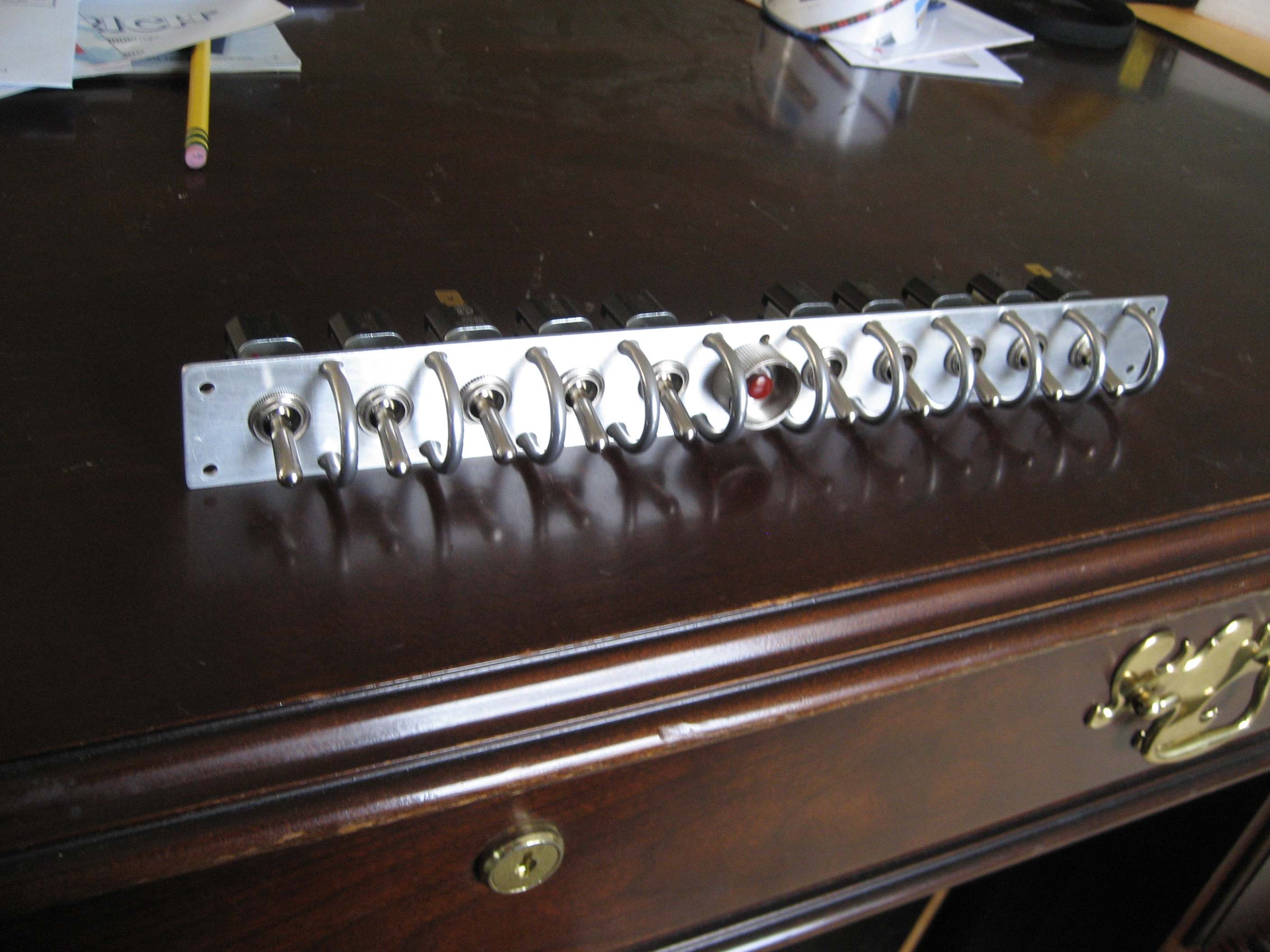
I took my aluminum OSP plate and drilled the holes for the switches and switch guards. At this point I’m not 100% certain of the sequence so this is just a temporary switch panel until I can determine which switch goes where.

Here’s the temporary OSP.
2010-11-20 1221 IMG_0805

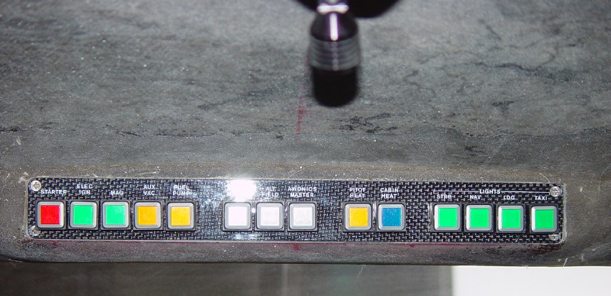
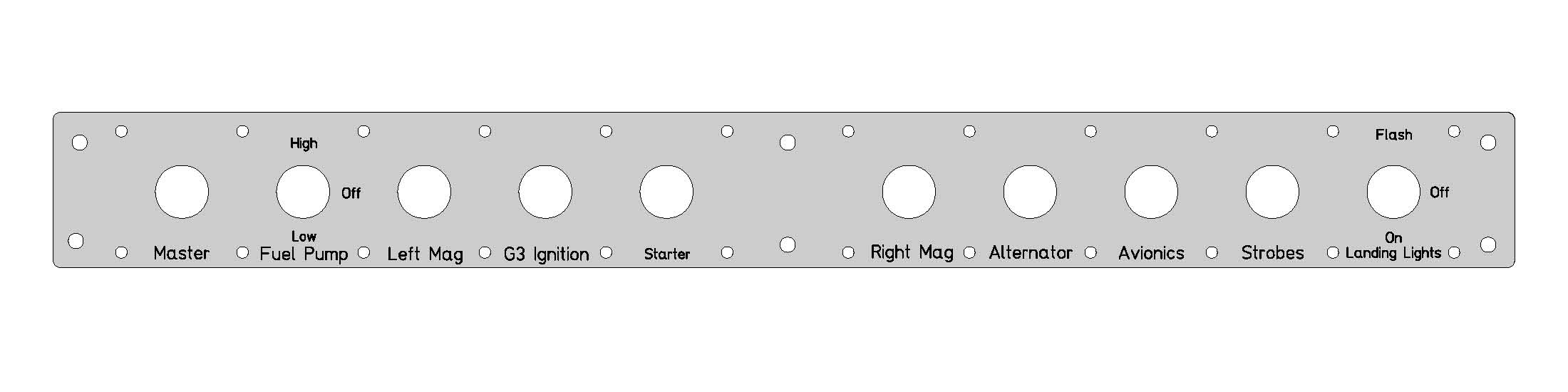
Once I’ve got the sequence determined, I’ll use a service like Frontpanelexpress to cut, drill and engrave the finished panel. Here’s what I think it will be.
OHP

14.2.1 Strake Extension

This entry is part 25 of 38 in the series 14 - Final Assembly / FInishing

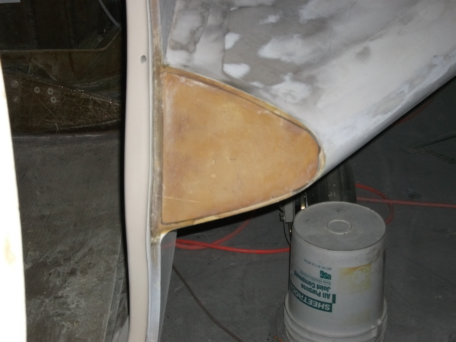
Where the strakes meet the door and fuselage, there’s a small space. Most people put a partial cover over it and use it for storage. There’s really not much room and it’s open to the elements so I decided to simply cover it up. So I cut a thin piece of plywood, glued it in place and then covered it with a later of BID.
2010-11-29D

6.3.2 Front Seat Rails

This entry is part 38 of 42 in the series 06 - Fuselage

I’ve already installed hardpoints in the seatpans and mounted the seatback. But after talking with the people that will be making the foam cushions (Oregon Aero), I found out that they can make the compressed thickness (how thick the cushion as when you’re sitting on it) to your specifications. They recommended installing the seat to see how much headroom I’ll have first.

This is where having the plane in SC kinda sucks. So next time down, I brought the pilot seat and put some foam blocks on the floor which put the rear of the seat at the height with the same angle that the rails would have. And that’s when I discovered the problem. With an inch and a half of foam between me and the seatpan, my head was jammed into the roof. When I moved the seat so that I could reach the pedals, I couldn’t reach the stick. If I moved the seat forward so I could reach the stick, my knees were elevated so that my thighs were no longer supported by the seat. So I needed to lower the rear (to get headroom) and raise the front (to support my legs).

Here’s the result:
2010-12-22B

Now the problem is that the rails will have to be modified.

Here’s the factory rail.
DSC_0042

Normally people mount these upside down from this picture. That way as you slide the seat forward, it also raises the seat. To gain more headroom, I removed the bottom straps and replaced the top straps with a pair that are taller in the front.

Here it is after a ton of thought and modifying.
2010-12-22D

Modified seat rail installed with me at the controls.
2010-12-22C

I’ve sent the pictures and dimensions to Oregon Aero and now I’m waiting to hear back.

5.2.3 Door Fit (Improving)

This entry is part 12 of 16 in the series 05 - Doors / Windows

At this point, the doors have been “encouraged” into the correct position as much as possible. They’re still not done. To get the rest of the way will require the sleeves around the door frame to be reinstalled so that the latching pins will engage more smoothly. When I modified the door latch mechanism, these had to be removed.

The first task is cutting new sleeves (4 for each door). Then with me inside, the door is closed and latched. Then Malcolm pushes on the door until it’s flush on the outside. While he’s holding it, I determine how much space exists between the door frame and the sleeve. Then it’s out of the plane and we temporarily glue a small wooden spacer (of the correct thickness to the sleeve.  Then back into the plane, the door is closed and the sleeve/spacer is glued to the door frame.

Here’s what it looks like.

2010-12-31A2010-12-31B

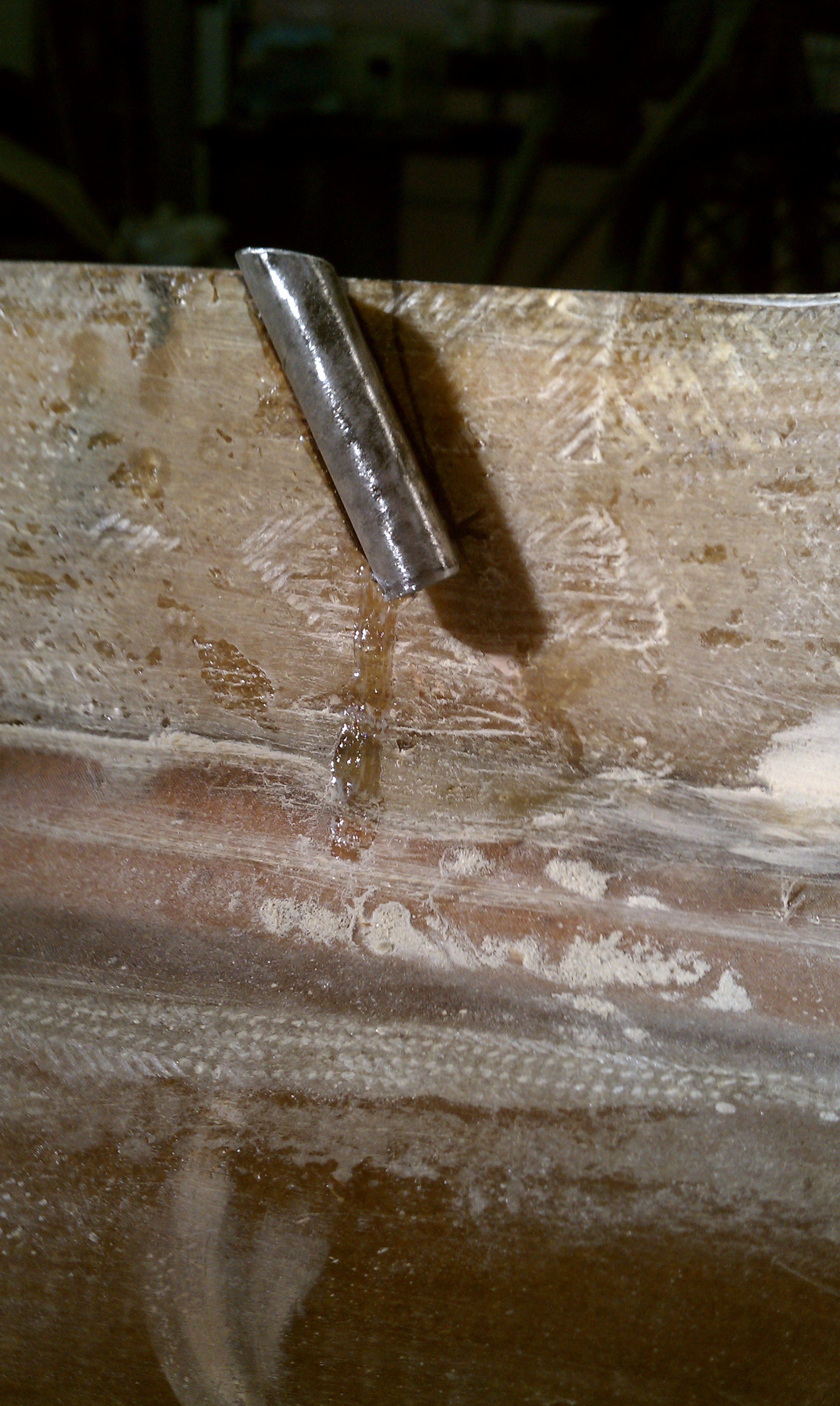
This is temporary though. The sleeve can still move some. Now it gets potted in place with an epoxy/milled-fiber/cabo mix. Malcolm has a trick for making a nice end product for this assembly. Rather goop the epoxy around the sleeve and try to make it look nice, he had cover some thin cardboard with foil tape and cut to make a barrier.

       2010-12-31C 2010-12-31D

The first one needs to be open at the bottom for a micro switch. So a “cap” is put on the bottom of that sleeve. On the other sleeve, the bottom just gets covered over.

Then the epoxy mix is spread over the sleeve. Once it’s cured, we sand it smooth and cover with 2xBID.

The doors are officially “relaxed”. Into position, that is.

Here are some pictures of the doors after a lot of time under the lamps.

2010-12-24B2010-12-24C2010-12-24E

2010-12-24G2010-12-24H2010-12-24I

I can’t tell you how pleased I am with the results. Before this process, it was looking like large amounts of filler would be required to make the door fit look good. This is just one of the advantages of having access to one of the premier Velocity builders.

Thanks Malcolm!