- 13.4.3 Pitot Tube Installation
- 13.4.2 Static Port
- 13.2.1 Instrument Panel Mounting
- 13.3.2 Ground Power Plug
- 13.0 Electrical System Documentation
- 13.0 Wire Labels
- 13.2.2 / 13.6.2 Aft wiring complete
- 13.8.1 Magnetometer connections
- 13.9.2 Autopilot Roll Servo Wire Routing Modification
- 13.7.1 Avionics Shelf
- 13.8.1 Magnetometer Mounting Bracket – Completed
- 13.8.1 Magentometer Bracket
- 13.1.6 Transponder Antenna Ground Plane
- 13.5.1 Navigation/Strobe Wing Root Connectors
- 13.0 Electrons are flowing
- 13.9.2 Autopilot Roll Servo Mounting
- 13.3.4 Overhead Switch Panel Wiring
- 13.2.2 Engine Wiring
- 13.6.2 Primary Alternator Connection
- 13.7.1 Avionics Shelf
- 13.8.1 OAT probe
- 13.2.2 EIS wiring
- 13.2 EFIS and Instrument Panel Layout
- 13.6 Ground Block – Part II
- 13.7.4 Headset jacks
- 13.3.4 Overhead Switch Panel
- 13.6 Ground blocks
- 13.8.2 Annunicator Panel
- 13.8.2 Annunicator Panel
- 13.8.2 Annunicator Panel
- 13.6 Electrical supply lines
- 13.6.3 Ground Power Receptacle
- 13.2 Instrument Panel Layout
- 13.3.5 Avionics Wiring
- 13.9.2 Auto Pilot Pitch Servo Mounting
- 13.7 Avionics and Wiring
- 13.7 Wiring
- 13.2 Panel painting
- 13.2 Panel installation
- 12.3.5 Minor setback on Avionics wiring
- 13.8.2 Annunciator Panel Problem
- 13.1.9 ELT Installation
- 13.6 Power Supply
- 13.7.4 It’s always something…
- 13.0 Wire routing
- 13.1.8 GPS Antenna Shelf
- 13.7.4 Audio Panel Relocation
- 13.0 Wire Routing (Remediation)
- 13.6.1 Battery Hold-Down
- 13.2.1 Instrument Panel – Final Install
- 13.3.3 / 13.5.3 Trim & Landing Light Test
- 13.8.1 EFIS alternate power
- 13.5.2 Cabin Lighting
- 13.1.4 Glideslope Antenna
- 13.3.4 Overhead Switch Panel
- 13.99 Instrument Panel overlays
- 13.99 Installing Engraved parts
- 13.99 Instrument Panel Lighting
- 13.4 Pitot/Static Remediation
- Static Port Conundrum
- GPS Replacement
- Secondary EFIS Power
- 13.99 Electrical System Diagram
- 13.99 – Current Sensor Repair
- 13.99 – ADS-B in antenna
- 13.99 – Switch panel update
- 13.4 – More Static Port Fun
When I’m not in SC, there are still things that I can do at home. Electrical system planning is one. I’ve already designed the courtesy lights. Now I’m working on the Overhead Switch Panel (OSP). The OSP is part of the A-Beam (it goes across the inside of the roof between the A-Pillars) and can have switches or indicator lights. There are many approaches to this. For example:
Andy Millin’s OSP

Terry Miles’ OSP

I don’t remember who’s this one is

Rich Guerra’s OSP
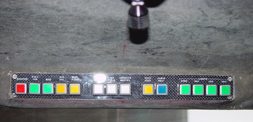
Fred’s OSP
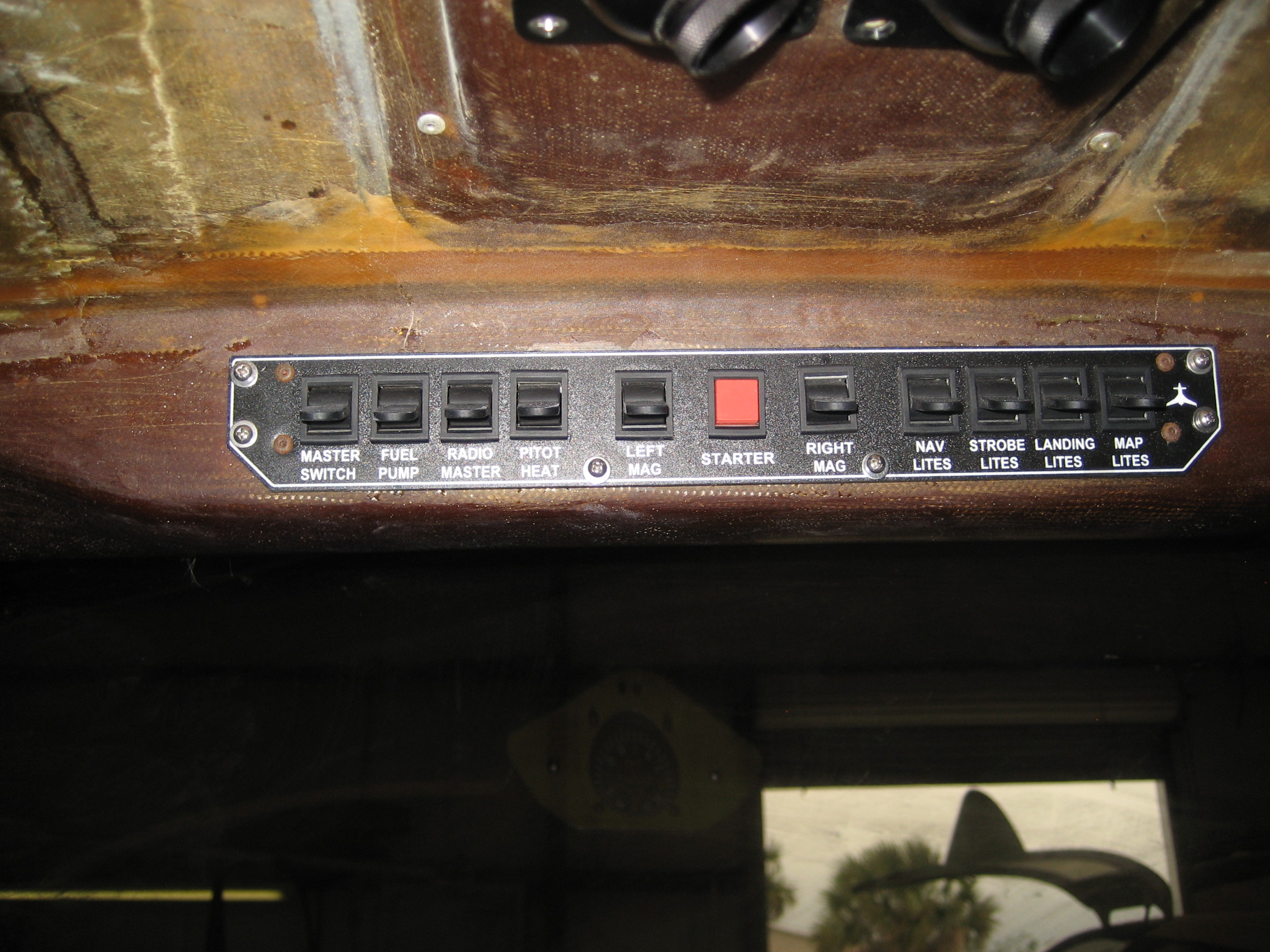
The Factory Demo Plane
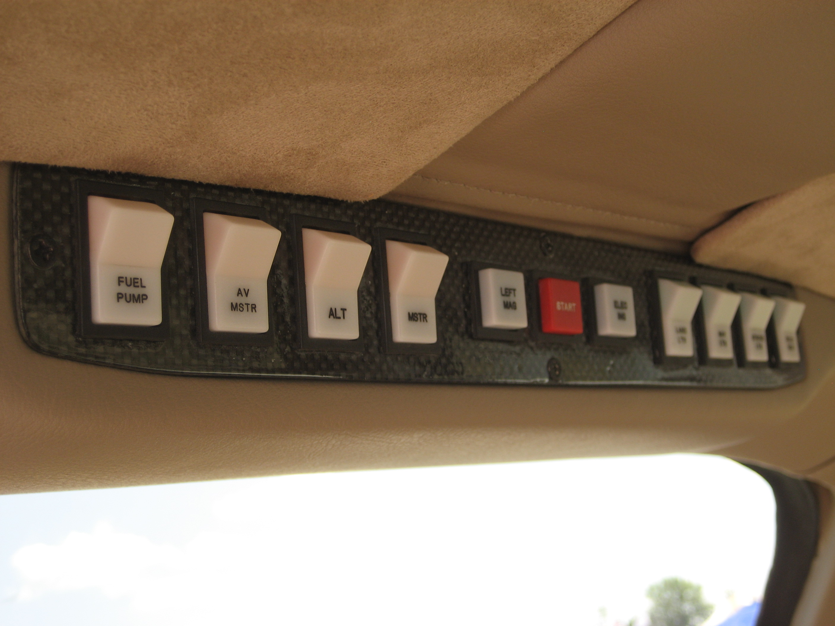
Now Andy has some really sweet lighted and engraved rocker switches! But because My A-Beam has a very low profile, I don’t have enough room for the rocker switches that Andy is using. So I decided to go with traditional toggle switches.
There are a couple issues to be dealt with on this panel.
- It’s real easy to reach for one switch and hit some turbulence and end up turning something on or off that you didn’t mean to.
- Most of the time when you’re flying, you are either looking outside or at your main instrument panel. If you’re flying IFR (Instrument Flight Rules) then you’re looking only at your instrument panel.
Switching your view from outside (straight ahead) to the main panel isn’t that difficult. You move your eyes a little and refocus. We do that every day when we drive. But looking at the OSP will possibily require moving your head and refocusing your eyes to something less than 12 inches away. This can be very distracting. So it would be nice to not have to ever look at the OSP when flying.
Here’s how I’m going to deal with these.
- I’m going to install switch guards on all the switches. That way, it will be almost impossible to “bump” into an adjacent switch. They also give your hand something to rest on when you’re activating a switch.
- I will also only use the switches for functions needed during engine start and engine shutdown. This way, I’ll never have to even think about these switches during flight.
- The sequence on activating the switches will be left-to-right for engine start and right-to-left for engine shutdown.
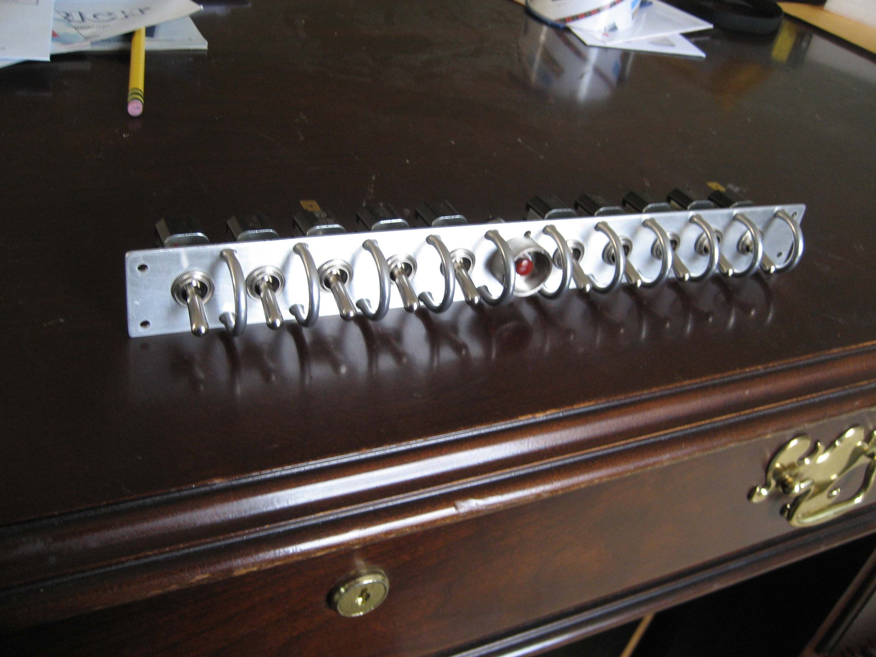
I took my aluminum OSP plate and drilled the holes for the switches and switch guards. At this point I’m not 100% certain of the sequence so this is just a temporary switch panel until I can determine which switch goes where.
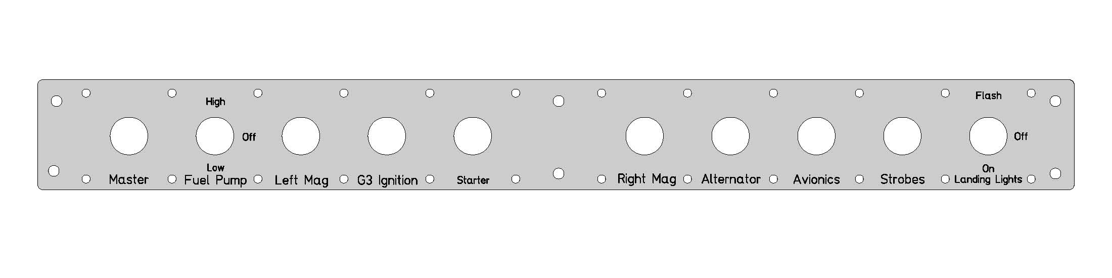
Here’s the temporary OSP.
Once I’ve got the sequence determined, I’ll use a service like Frontpanelexpress to cut, drill and engrave the finished panel. Here’s what I think it will be.