11.1 Engine Cowl

This entry is part 8 of 17 in the series 11 - Fairings

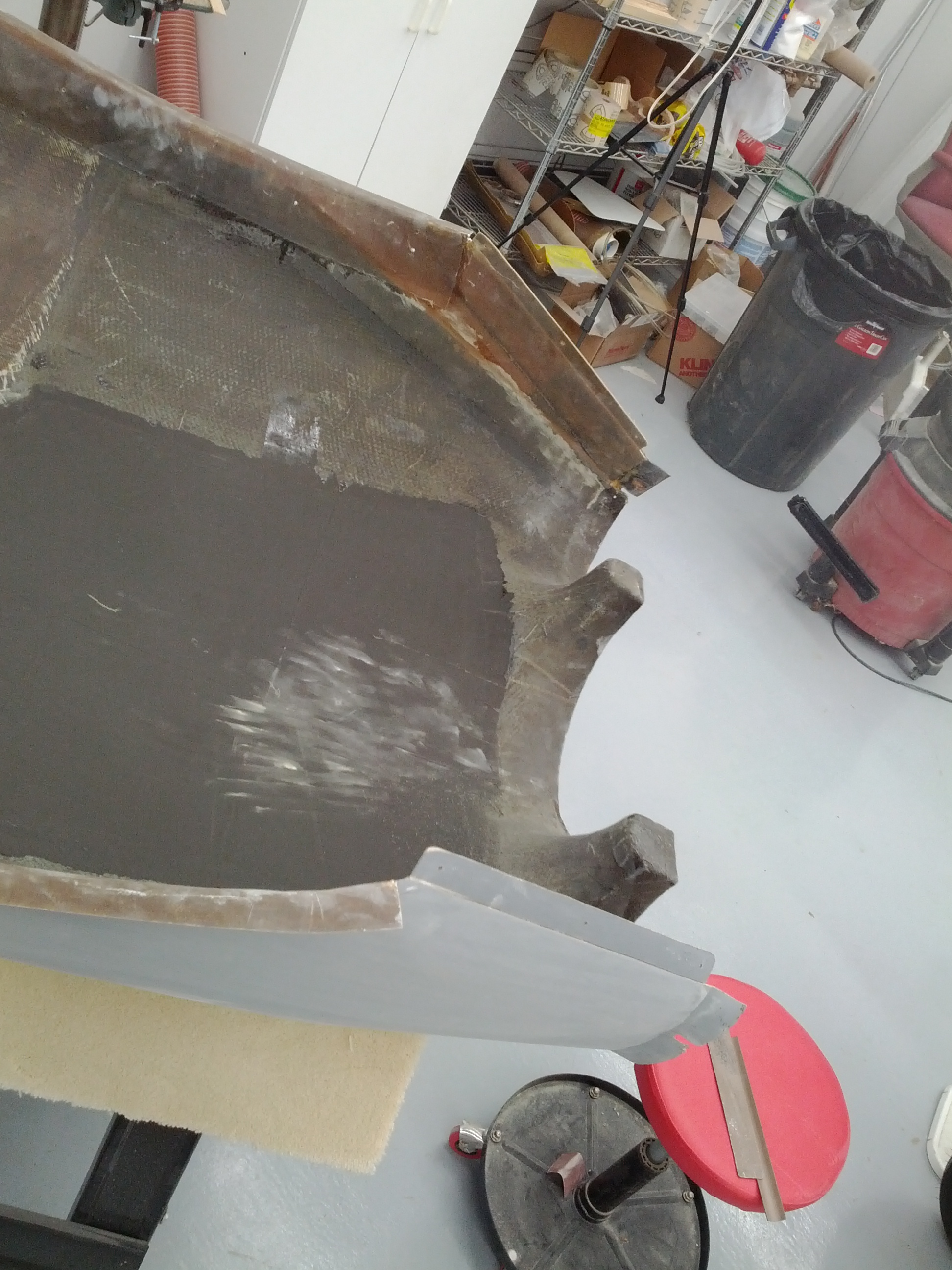
I finally got the top of the engine cowl fair. Before I cut the oil access door, I’m going to join the upper and lower cowl at the rear. First area around the openings for the prop and air are cleaned up.

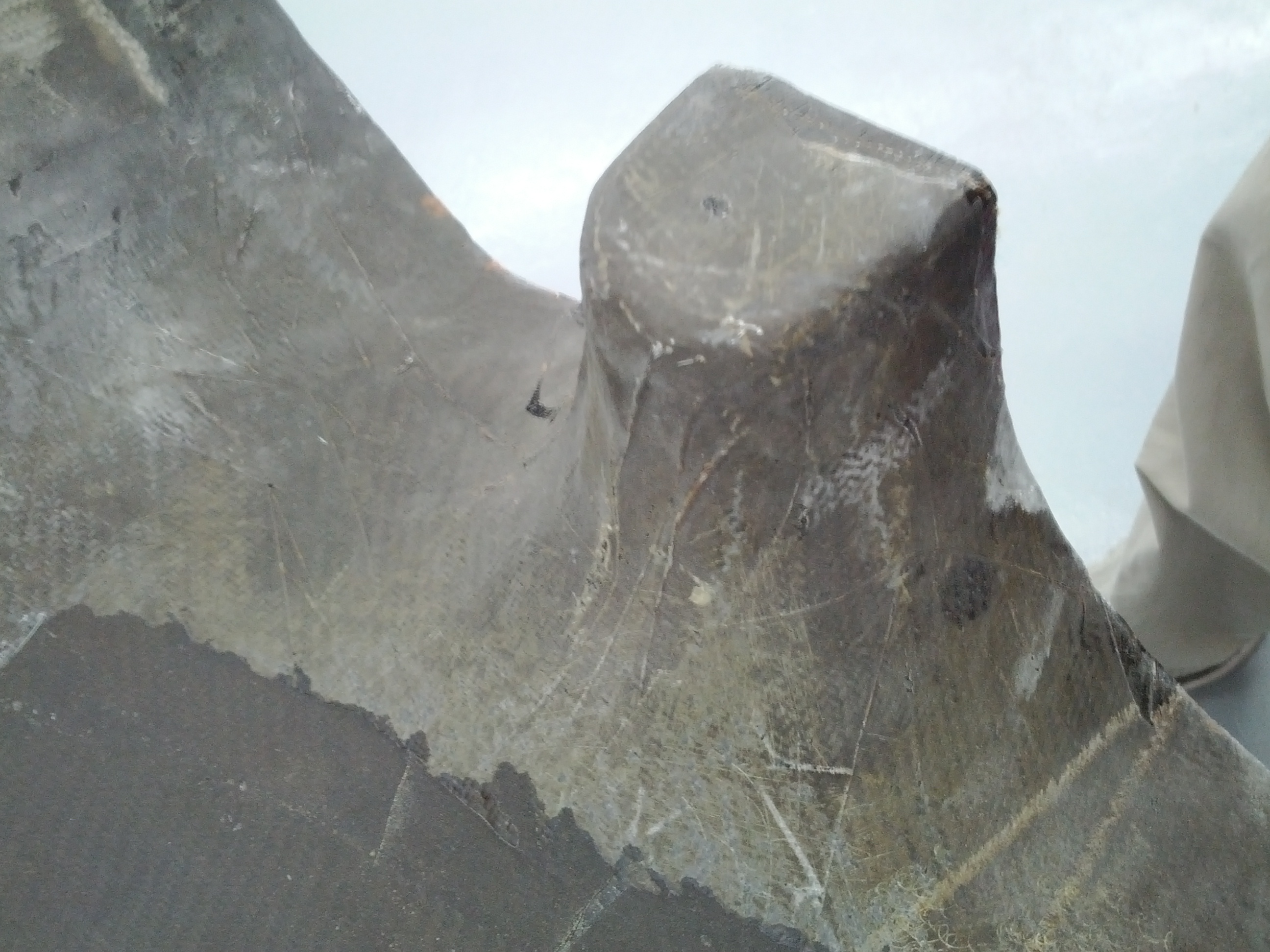
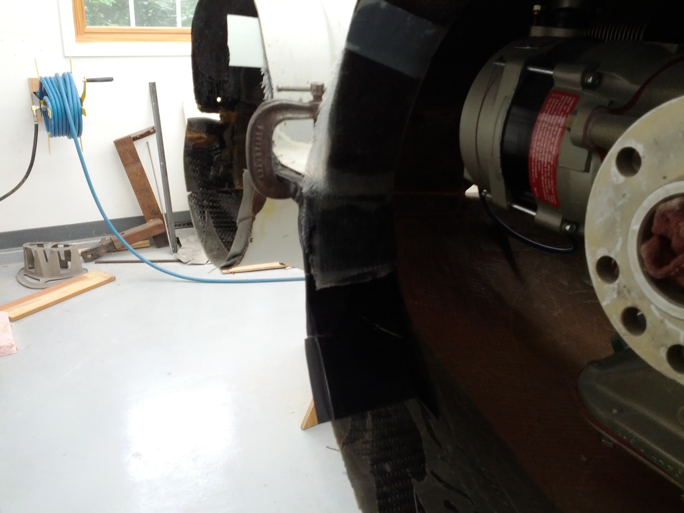
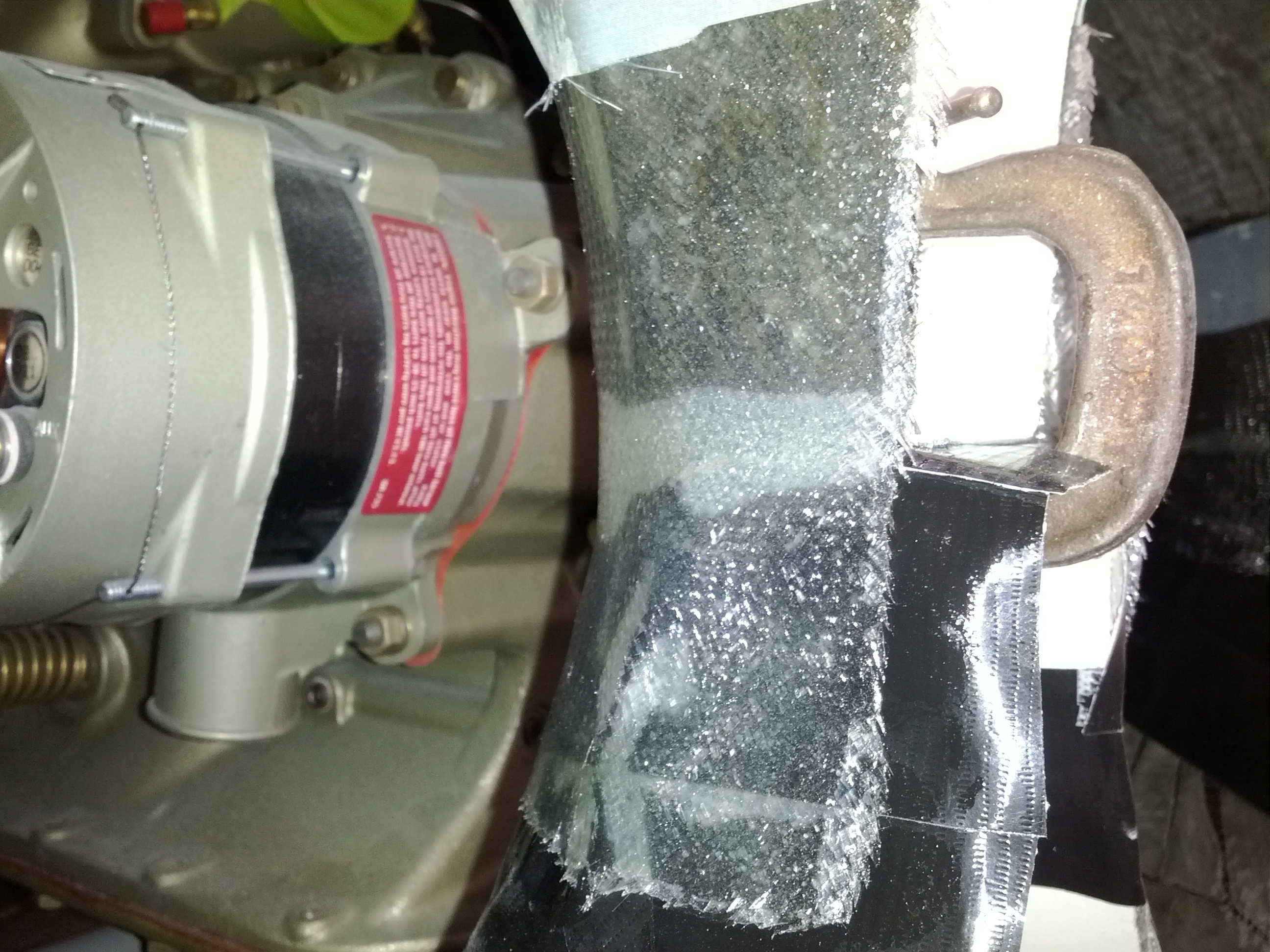
Then duct tape is applied to the inside of the bottom half and the top half is sanded. The two cowl halves are installed and clamps are used to hold the rear of the cowl together. Then a five BID layup is used to create a flange on each side of the prop opening.

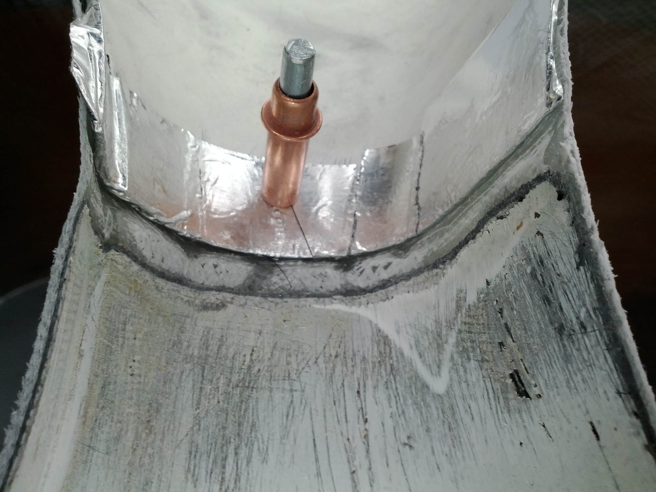
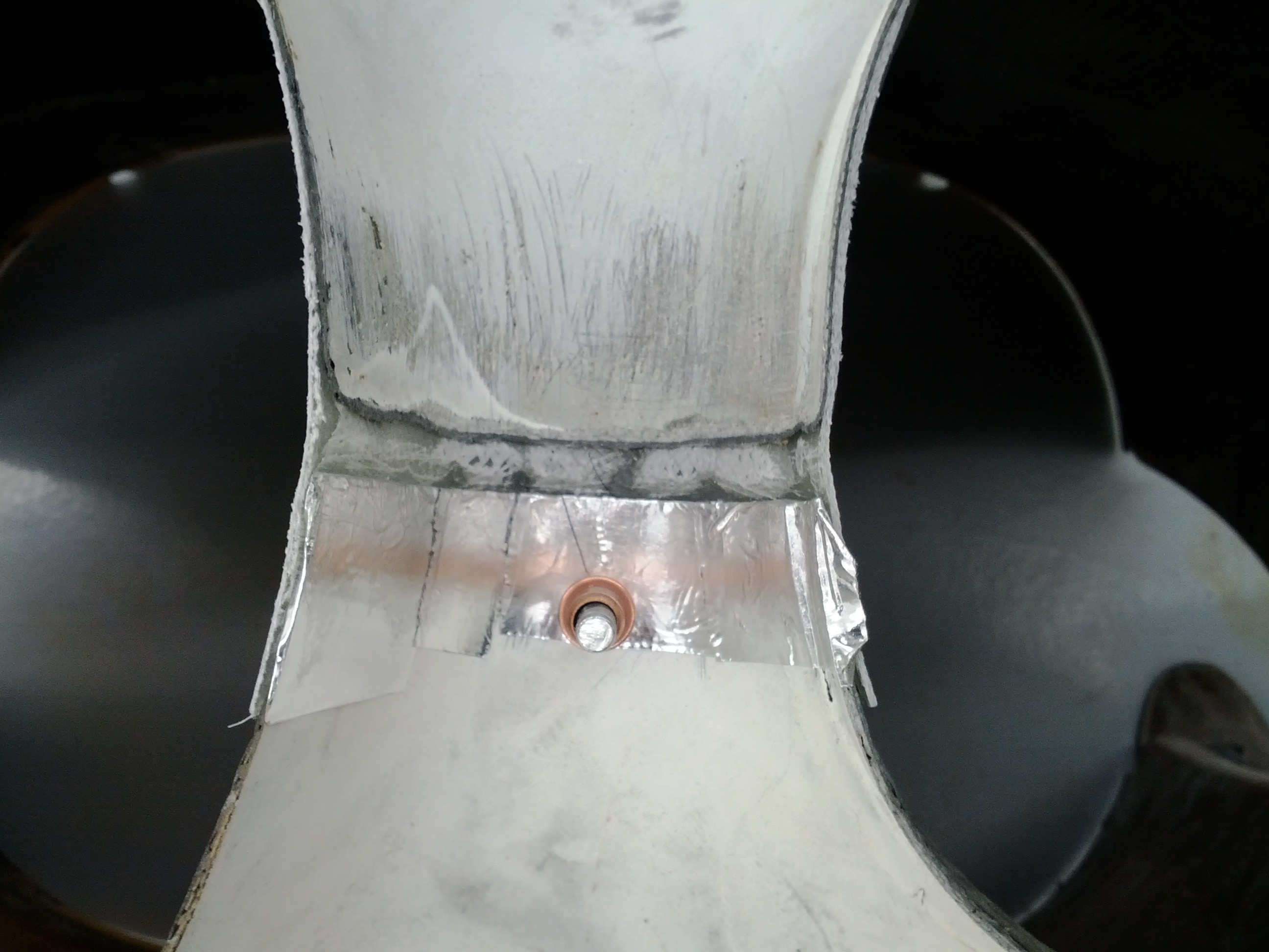
Once the layup has cured, a hole is drilled that will hold the two halves together and the manufacturing flange is cut away. Then the gap between the two halves is filled.

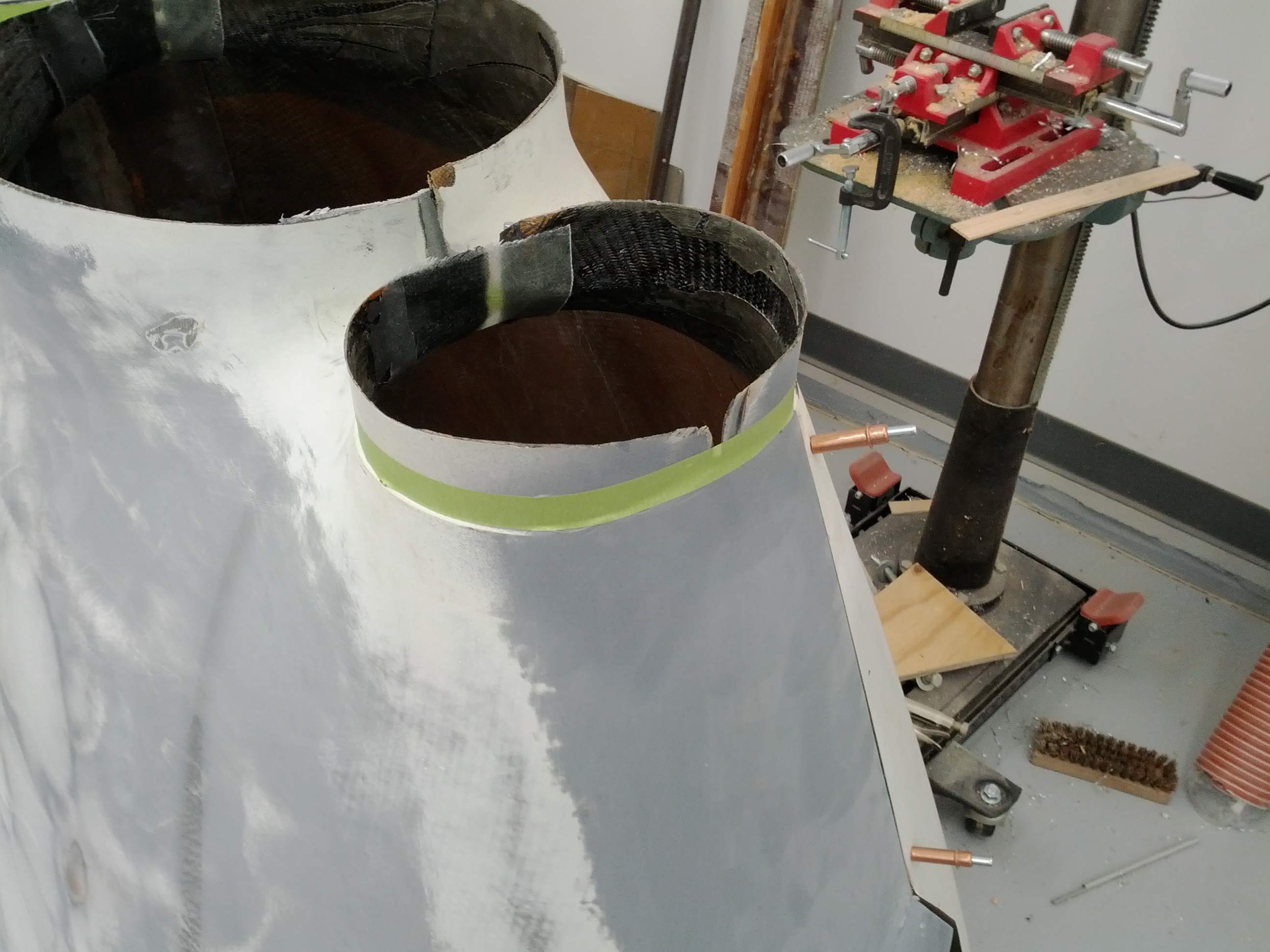
After filling and sanding are done, the air outlets are cut down to their final dimension. Malcolm suggested using 3/4″ masking tape on the step which provides a 3/4″ line.

11.1.6 Oil Access Door

This entry is part 9 of 17 in the series 11 - Fairings

I finally finished the finishing on the upper cowling. Until it’s in shiny white primer, I won’t know how good it is, but it feels like it has the right lines.

Now it’s time to cut the oil door. The manual has you draw a 6 inch diameter circle and flatten one edge and put a hinge on it. Then a screw is used to hold it closed. I picked up a hidden hinge and recessed push button latch from the RV guys. So the first thing is to determine the location of where the door will go. To do that I installed the upper cowling and reached up inside and marked the inside of the cowling where the oil filler cap is. Then I removed the cowling and drew out the shape of the door. I decided to go with a “D” shaped door.

Since black marker doesn’t show up on carbon, I used masking tape for the layout.

I then cut all the straight lines. Here’s the top view with only the curved parts left.

Then position the hinge and drill the holes before cutting away the door.

I don’t have a blade narrow enough to cut the curves near the hinge so I drilled a series of small holes.

To keep it from binding while making the final cuts, duct tape will hold it in position.

An oil filler access door.

To make sure it’s in the correct location, I installed the cowling to verified the position.

Then I covered the bottom of the door and made a flange with 4xBID. Once it was cured, I trimed away the excess leaving a flange (or lip) that the door would rest against.

Next I positioned and drilled for the recessed latch. Here’s everything held together with cleco’s.

I’m a bit concerned about the clearance with the J-hinge. It’s REALLY close.

But I’ll wait and see how much movement the engine has before I make the call on that. Best case is I have enough room. Next best is I could trim part of the hinge. Worst case is having to come up with a different hinge.

12.3.1 – Installing Throttle, Mixture, and Prop Controls

This entry is part 15 of 50 in the series 12 - Engine / Propeller

I have been dreading pulling the engine control cables from the front of the cabin through the left wiring duct to the back of the plane. After we got the oil lines installed and pulled the brake lines, it just started looking like getting the engine control cables through was going to be a problem.

So me and my son Steve spent about an hour trying different things and finally got all three control cables through.

Here’s a picture on the engine controls on the permanently mounted “Engine Control Sub-Panel” (another Hangar 18 innovation).

A view from the side.

Where they exit at the firewall.

12.3.1 – Mixture Control Mounting Bracket

This entry is part 16 of 50 in the series 12 - Engine / Propeller


The factory supplied “Engine Installation Kit” comes with a number of pre-fabricated parts. One of those is the bracket that mounts the mixture cable.

Here’s what the factory supplied bracket looks like.

But when I tried to install it on the engine, the mounting holes lined up properly, but the plate was hitting in a couple places. I thought that I might have it installed backwards or in the wrong location but according to the manual, it was in the right place. So why isn’t it fitting? The mounting bracket is for a Continental IO-550N and that’s the engine I’ve got. So I must be doing something wrong. After scratching my head and trying different approaches, I finally decided to modify the bracket. Here’s what I ended up with:

And it fits perfectly. It would be SO MUCH EASIER if the manual just said “this part will require modification to clear existing nuts, bolt and other obstructions.” But no… you gotta figure that out on your own. 🙁

Here’s the bracket installed.

Clears all the obstructions, but it looks… wrong.

Back when I had the intake tubes built, I purchased some Continental Gold engine paint. See where this is going? 😉

Much nicer!

12.3.1 Prop Control Bracket

This entry is part 17 of 50 in the series 12 - Engine / Propeller

Once the Mixture Control Bracket was installed, I moved on to the prop control. This one looked to be a bit easier. It’s just an “L” shaped piece of aluminum with pre-drilled holes to mount it to the engine. Which means that all I need to do is located and drill the holes for the prop cable clamp.

Except that when I tried to put the bolt through the hole to mount the bracket to the engine, the bolt didn’t fit in the hole. By this point, I didn’t waste any time thinking about it, I just enlarged the holes to accommodate the bolts. Once that was done I mounted the bracket and determined where the holes for the cable clamps would go then drilled those.

Here’s the bracket with the cable mounted looking from the side, bottom and rear.

But, of course, I don’t like the silver aluminum color so it gets painted too.

Next is the throttle control. And that one looks like it will be a real pain. 🙁

12.3.1 Throttle Control Bracket

This entry is part 18 of 50 in the series 12 - Engine / Propeller

I had already done a little checking and I could not get the throttle control cable bracket to fit. I tried a couple different approaches but it just wouldn’t fit. So I started modifying it (much like I did with the mixture control bracket).  Put it on, see where it hits, take it off, file some material away, put it back on. And repeat, repeat, repeat. 🙁

After about TWO HOURS, I threw in the towel and got a piece of aluminum angle. After about 90 minutes, I had a bracket.

On the top is the factory bracket. The bottom is the one I made.

At first glance, it would appear that I could have accomplished this by simply taking off more material. But the problem was where the cable clamp mounted. Those are the holes in the second picture. The first problem was that the bracket was too wide and hit the intake manifold. I couldn’t take any more material away or I would compromise the hole for the clamp. The second problem was the cable wasn’t aligning with the throttle arm. Which meant the cable (and clamp) had to be moved outboard. Hence the new bracket.

I’m not painting this bracket until I locate where the landing gear warning switch goes.


13.99 Instrument Panel Lighting

This entry is part 58 of 67 in the series 13 - Electrical / Instruments

I’ve got the glareshield trimmed and fitted. This was a major PITA. Lots of putting it in, figuring out where it was hitting, remove it, trim it, put it back in, mark it, remove it, trim it, put it back in…  I must have installed that glareshied 30 times. Then I made some tabs that will be used to attach the glareshield to the top of the instrument panel.

Now it’s time for the lights. I’m using a strip of blue LEDs. The LEDs are about .5″ apart so they will provide about the same type of light as the electro-luminescent lights.

The strip is about .2″ high and to keep the light out of the line of site, I could either create a raised area behind the strip or simply recess it. I chose to recess the strip of LEDs.

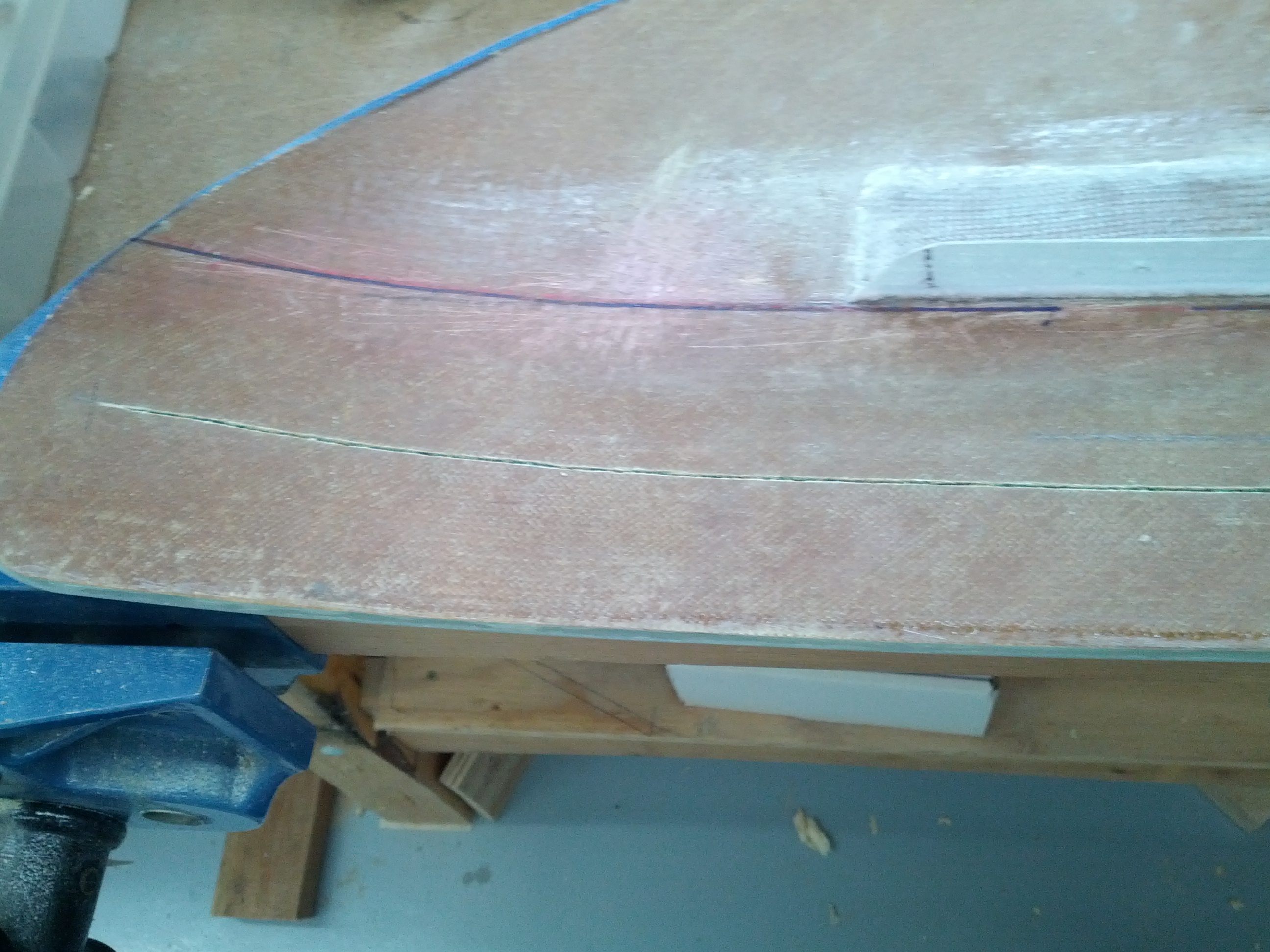
First I marked where the LED strip will be then I made the first cut through the bottom layer of glass.

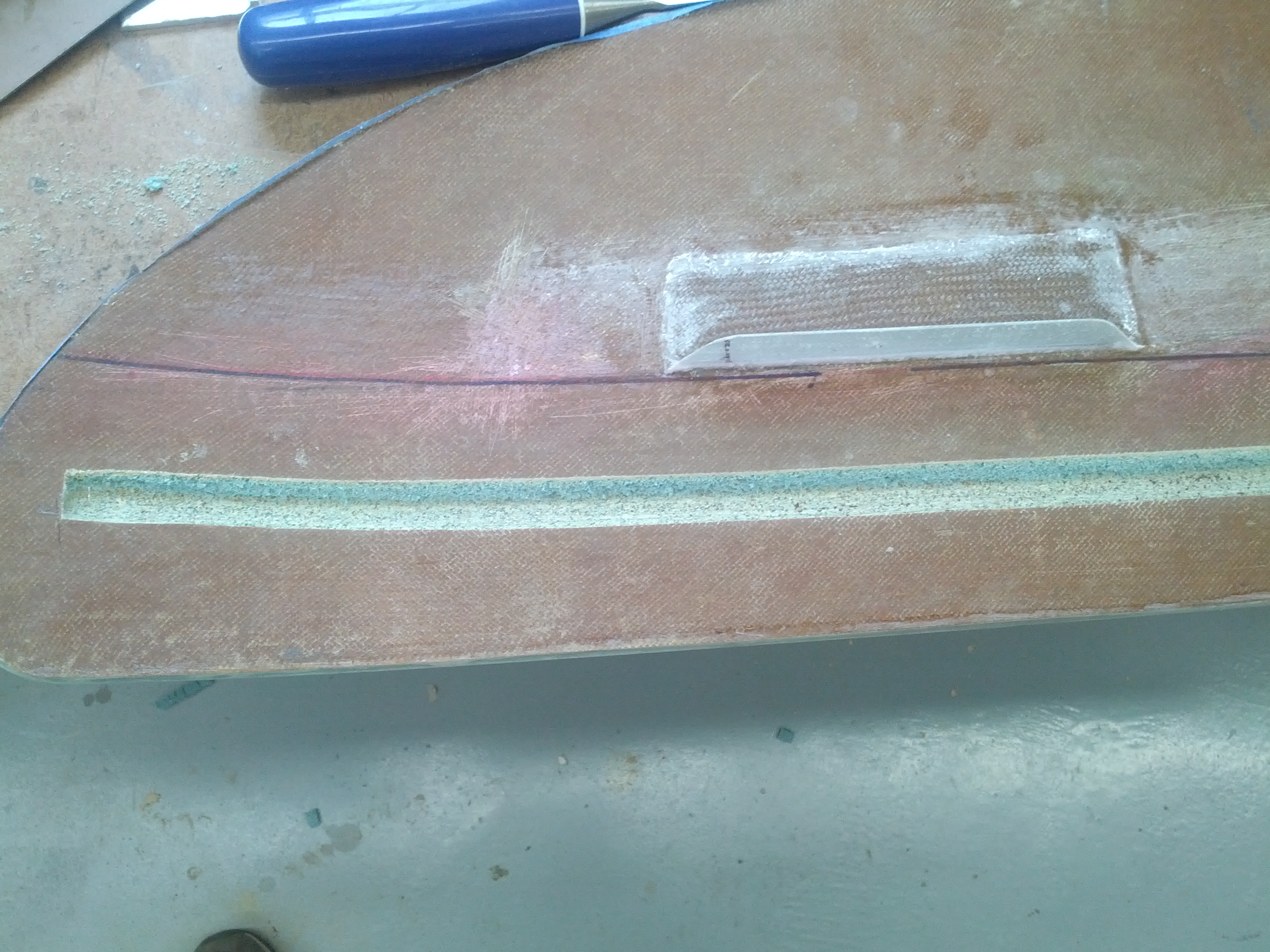
Then I made the second cut. I made this cut farther forward than necessary so I could slope the the opening.  After the cut was made, I removed the lower layer of fiberglass and cut out the foam. The result is a slot with the rear straight up and down but the front has a gradual slope towards the panel.

To accommodate the wires, I drilled a hole between the top and bottom layers of fiberglass that would be the wiring conduit. I used a long drill bit and started from the front edge and drilled back to the end of the slot on the pilots side. Then I drilled a hole from the bottom into the conduit.

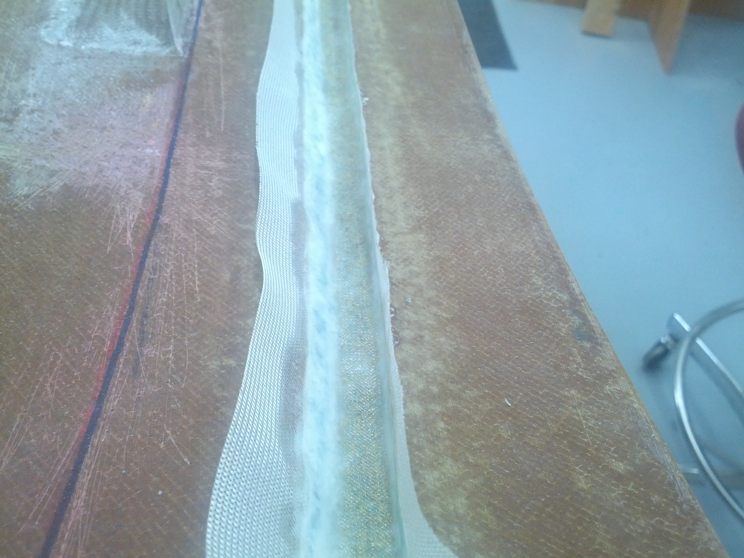
The slot is then covered with a layer of BID. Because of the small area, I used a fiberglass veil (very fine fibers).

Once that cured, I trimmed off the excess and painted on a coat of resin to make a smooth surface. The LEDs have a self-adhesive backing and I wanted a smooth surface for that to stick to. I’m not sure what I’m going to do as far as covering on the glareshield, but for now, I painted the underside flat black.

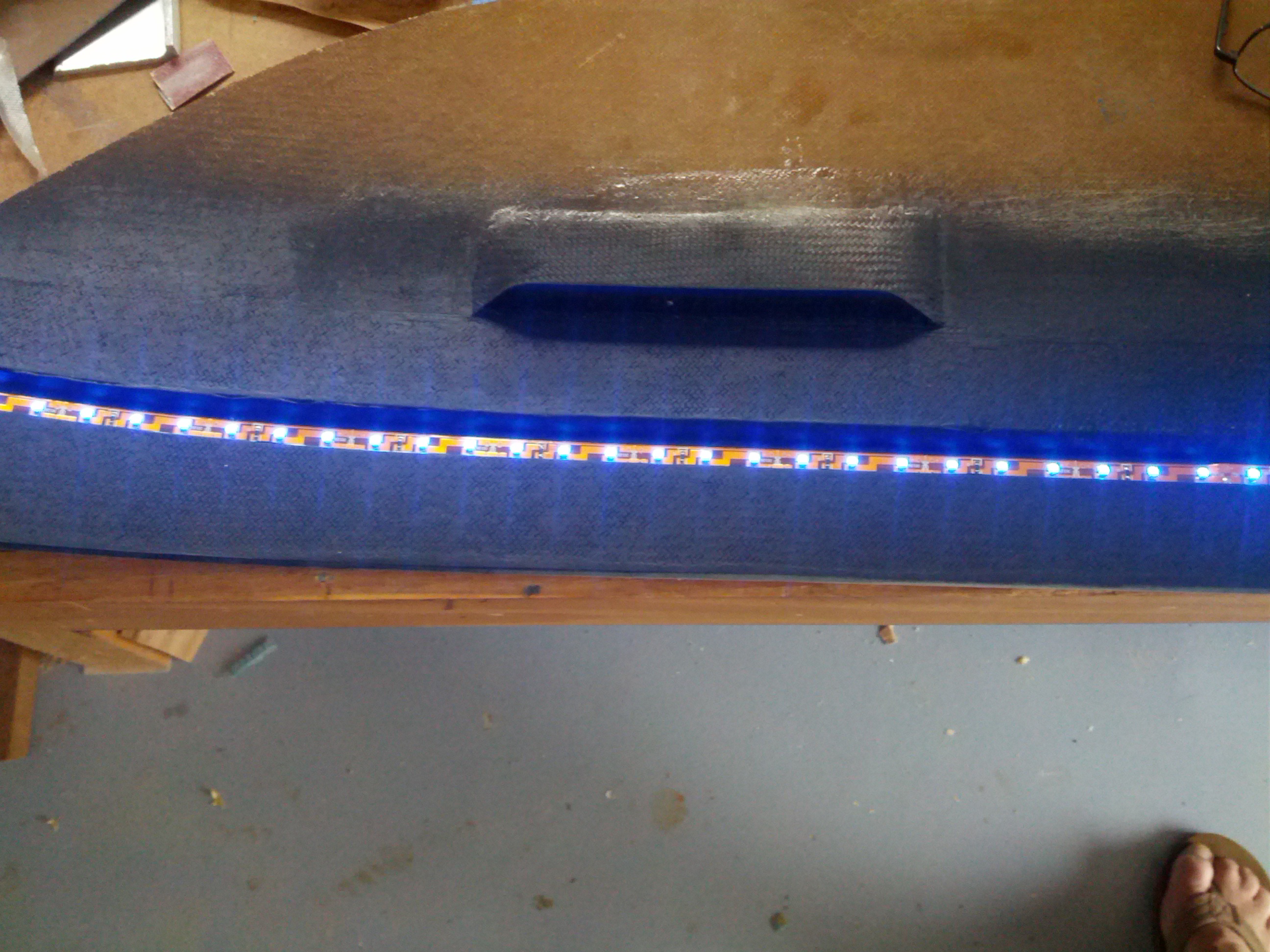
The LED strip is designed for a 12v system. Since I’m running a 24v electrical system, I had to modify the strip and turn it into a 24v strip. Once that was done, I installed the LEDs (little out of focus).

Then I connected the power.

I wanted to see how it would look installed, so once again, I put the glareshield back in.

I’m not nuts about the unlighted portion of the instrument panel at the very top. Mounting the LED strip on the bottom of the glareshield or increasing the slope would have prevented that. But I think I’ll let it go since there’s nothing in that area that needs to be illuminated anyway.

10.2.1 Rudder Cable Connections

This entry is part 9 of 11 in the series 10 - Control Sytem

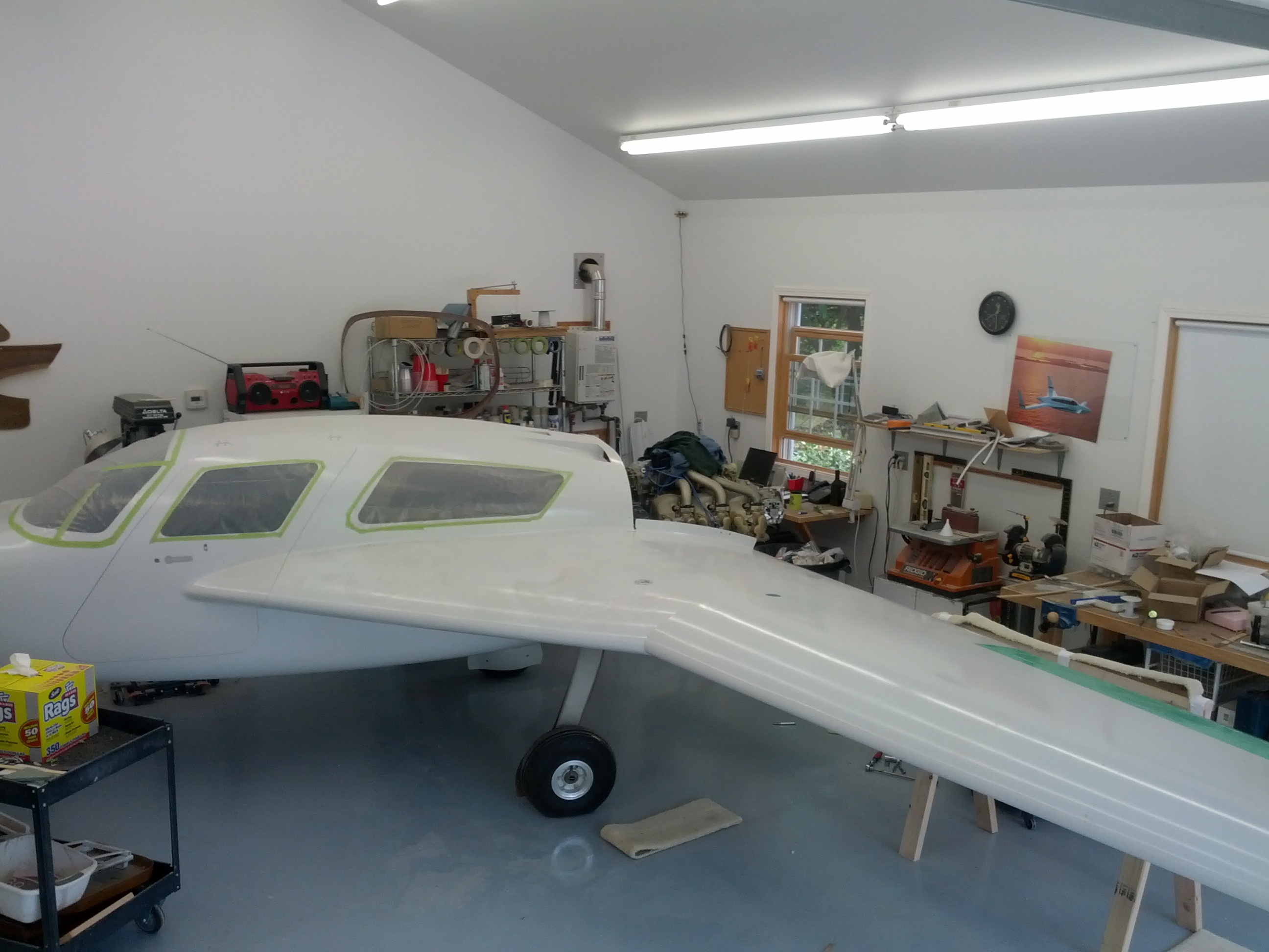
I need to finish the aileron and rudder cable installation.  For this, the wings need to be on. But since my shop is much smaller than Malcolm’s, I can only do one wing at a time. So I repositioned the plane and Steve helped me hang the pilot side wing.

10.3.1 Aileron Control Cable

This entry is part 6 of 11 in the series 10 - Control Sytem

Before the plane came back from South Carolina, we connected the aileron control cables. They worked, but the routing of the cables wasn’t perfect. Malcolm was very happy with the force required but the cable routing just didn’t look right to me.

So the first thing I did was to pull the cable from the firewall and open up the hole a bit. This will allow for a wider radius turn instead of the sharp kink it had. Once I reinstalled the cable, the routing was much better. But now I had a new problem.

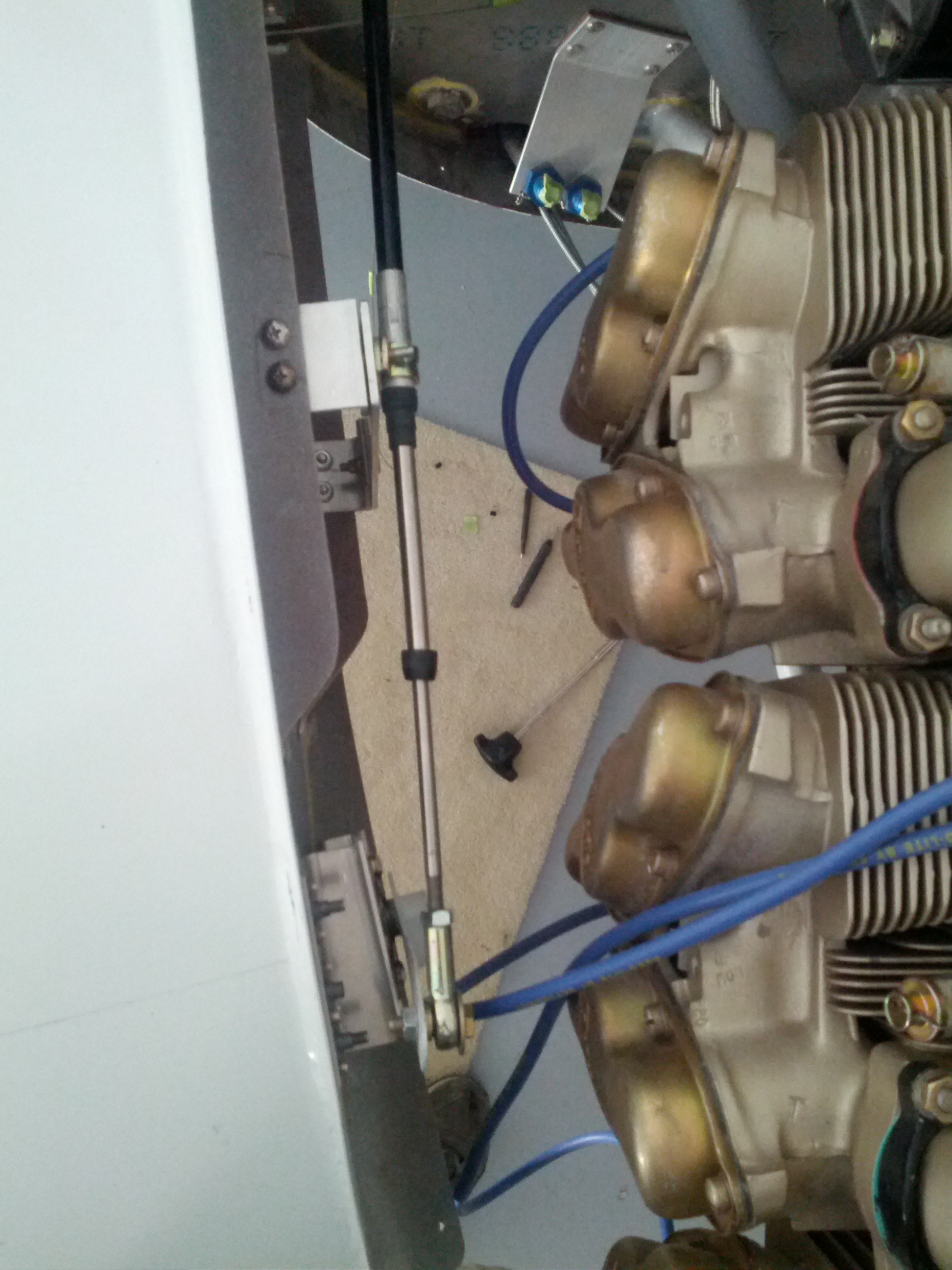
Here, you can see with the aileron up, the cable has a noticeable “break” to it at the point where it’s clamped.But the aileron is down, it’s pretty straight. It should be straight at the neutral position with a slight break when full up or down.

I fixed this by rotating the bracket that the cable clamps to. And since I opened up the hole in the firewall, the cable has a nice sweeping radius to it.

12.2.2 Fuel Line

This entry is part 42 of 50 in the series 12 - Engine / Propeller

Looking back from the firewall. The mechanical fuel pump is on the right. Oil filter is on the left. I put a fuel fitting on to see if there was enough room just for the fitting.

The same view from a little farther away and higher.


Looking down from above. You can see the firewall and fuel filter on the right. The oil filter is on the bottom. And you can see the (out of focus) fuel supply line on the right.

So the question is, do I leave it as it and route the fuel line up between the oil filter and fuel pump? Or do I try to rotate the fitting at the fuel pump so I can route the line forward of the engine?