11.1.2 Cowling attach mod

This entry is part 16 of 17 in the series 11 - Fairings

I used the cowling to the fuselage attachment method described in the book.  I thought about using approaches that other builders have used but decided to just get it done.

One of the things that I wish I had done was a captive flange at the fuselage attach point instead of a bunch of screws. Since I haven’t painted yet, I could to that but so far I’ve been deferring that decision.

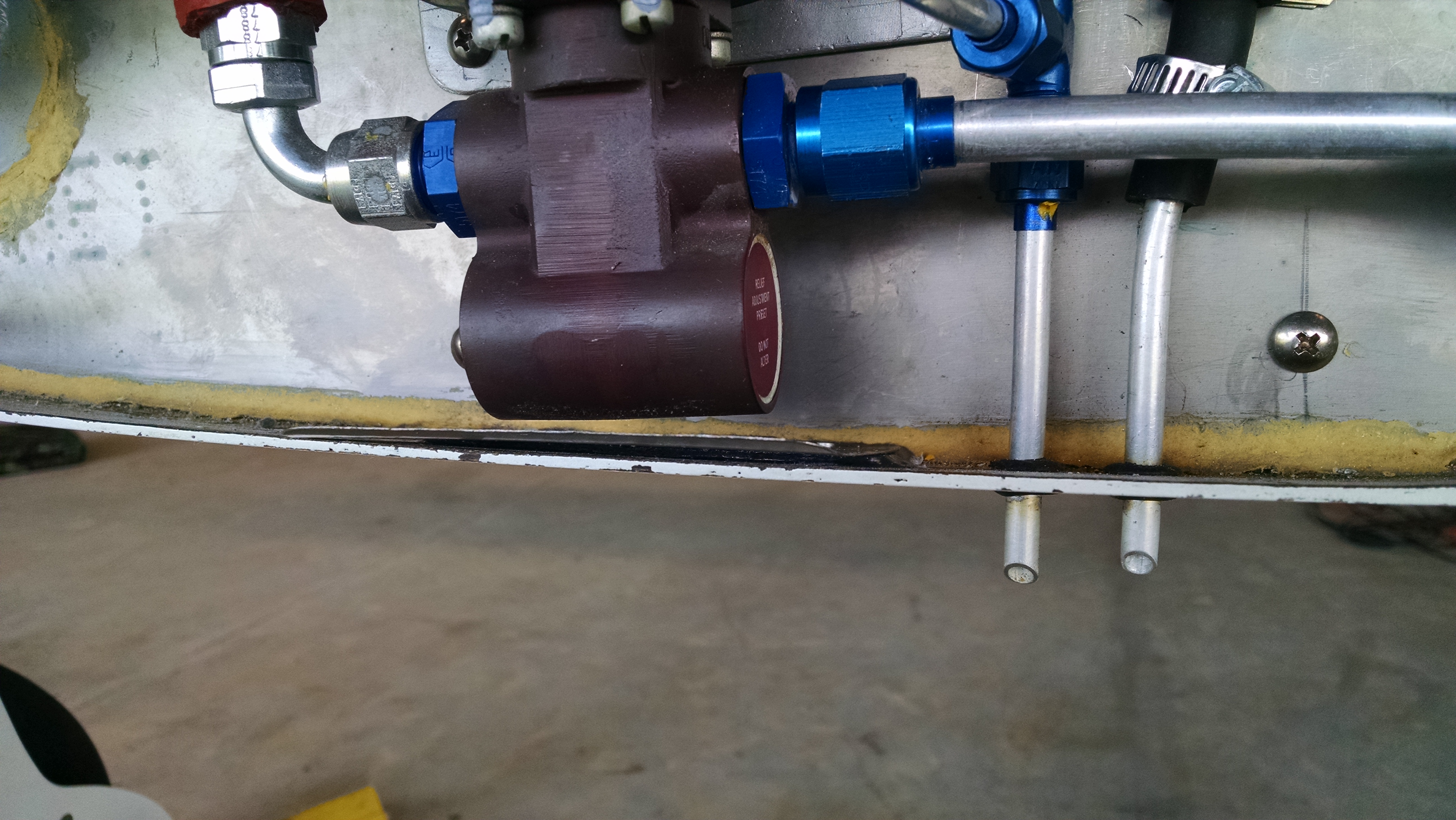
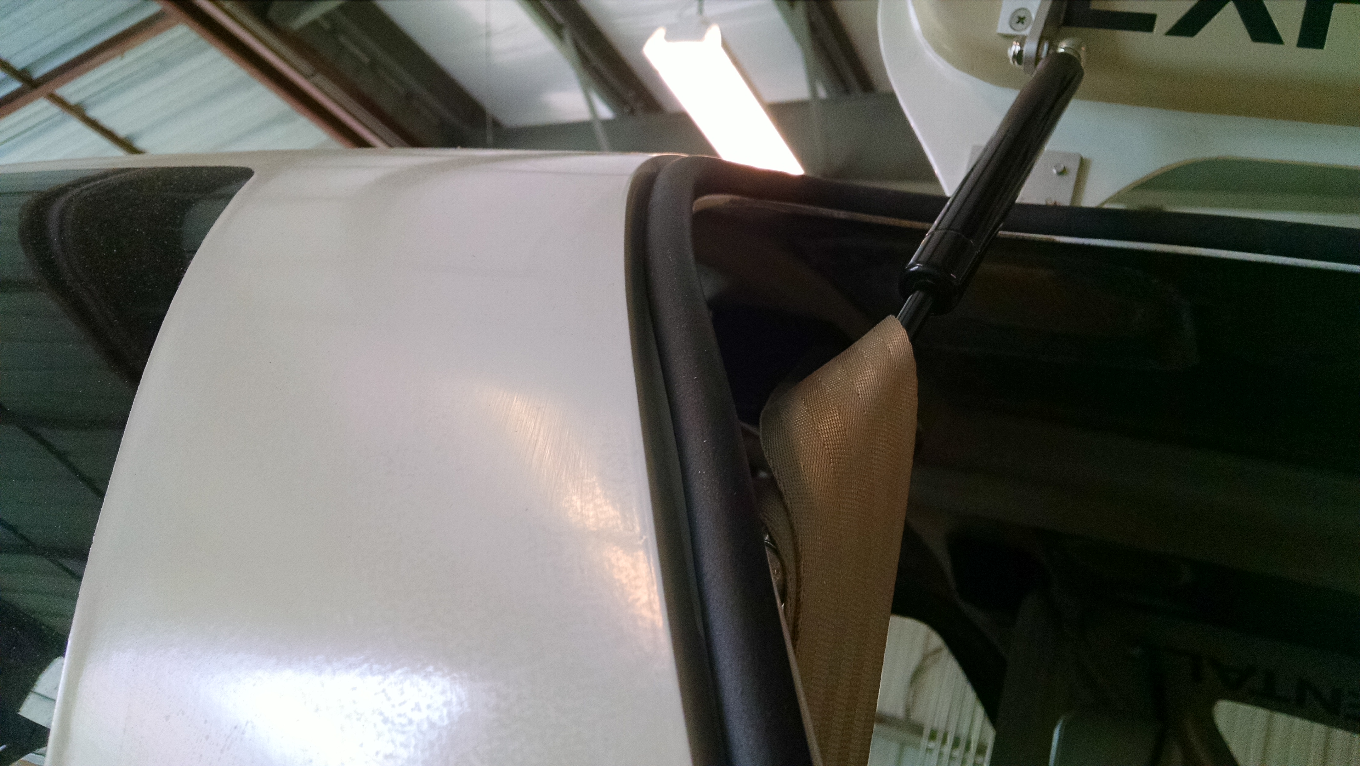
But I do have one place on the lower cowl that I have to deal with. When the hole were being drilled in the lower cowling, one of them ended up being directly under the electric fuel boost pump.  There’s not enough room for a regular nutplate.  Even a a low profile tinnerman would probably not fit.

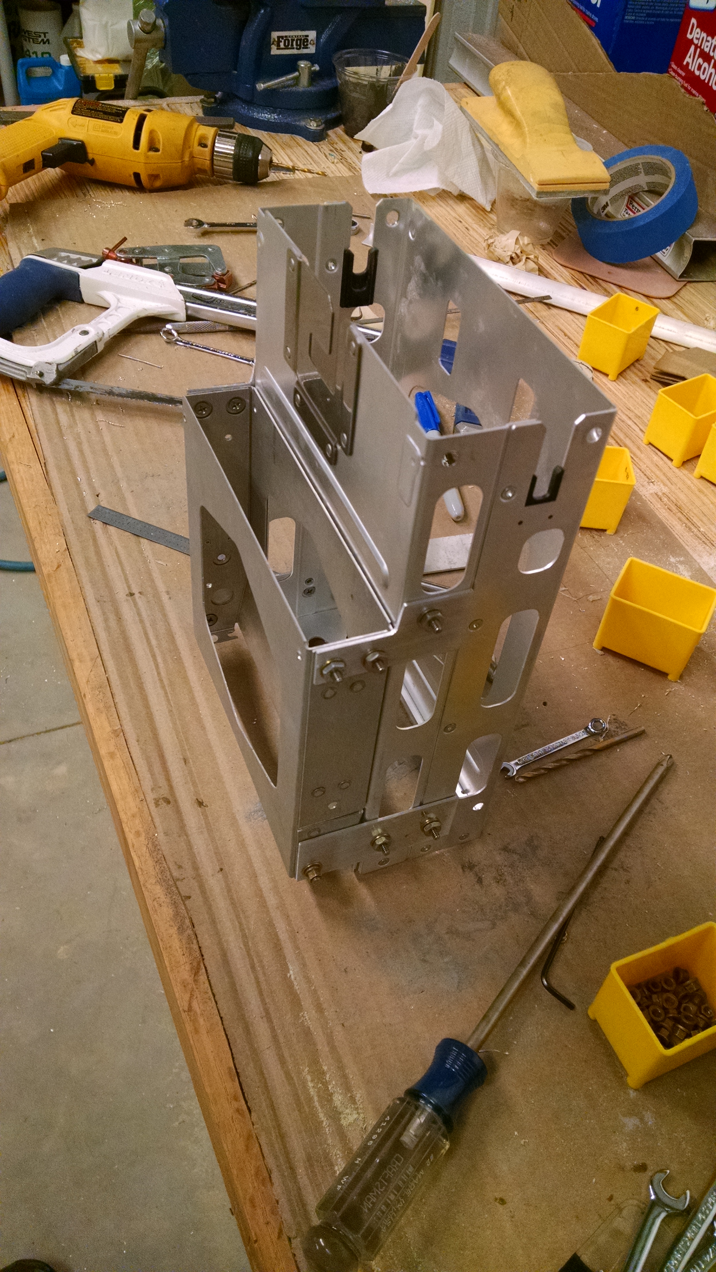
So I decided to do a captive flange under the fuel pump. FIrst I made a spacer with a couple layers of triax and BID.  This has to be the same thickness as the cowl flange. Then I cut a piece of leftover titanium that would extend aft from the firewall past the fuselage flange by about a half inch. Next I drilled four holes through the fuselage, spacer and titanium. Finally I put a film of structural adhesive between all the parts and riveted them in place.

IMG_20160604_135826562 IMG_20160604_135835483

Filling the countersunk rivets will be done during paint prep in the fall.

If I like how this works, I may do this all around the fuselage/cowling attach area. Then maybe use piano hinge at the wingroot.

17-1 Fuel Filter Tooling

This entry is part 1 of 1 in the series 17 - Maintenance

After having the flush the fuel tanks a number of times, I had to check and clean the fuel filter quite a few times as well.

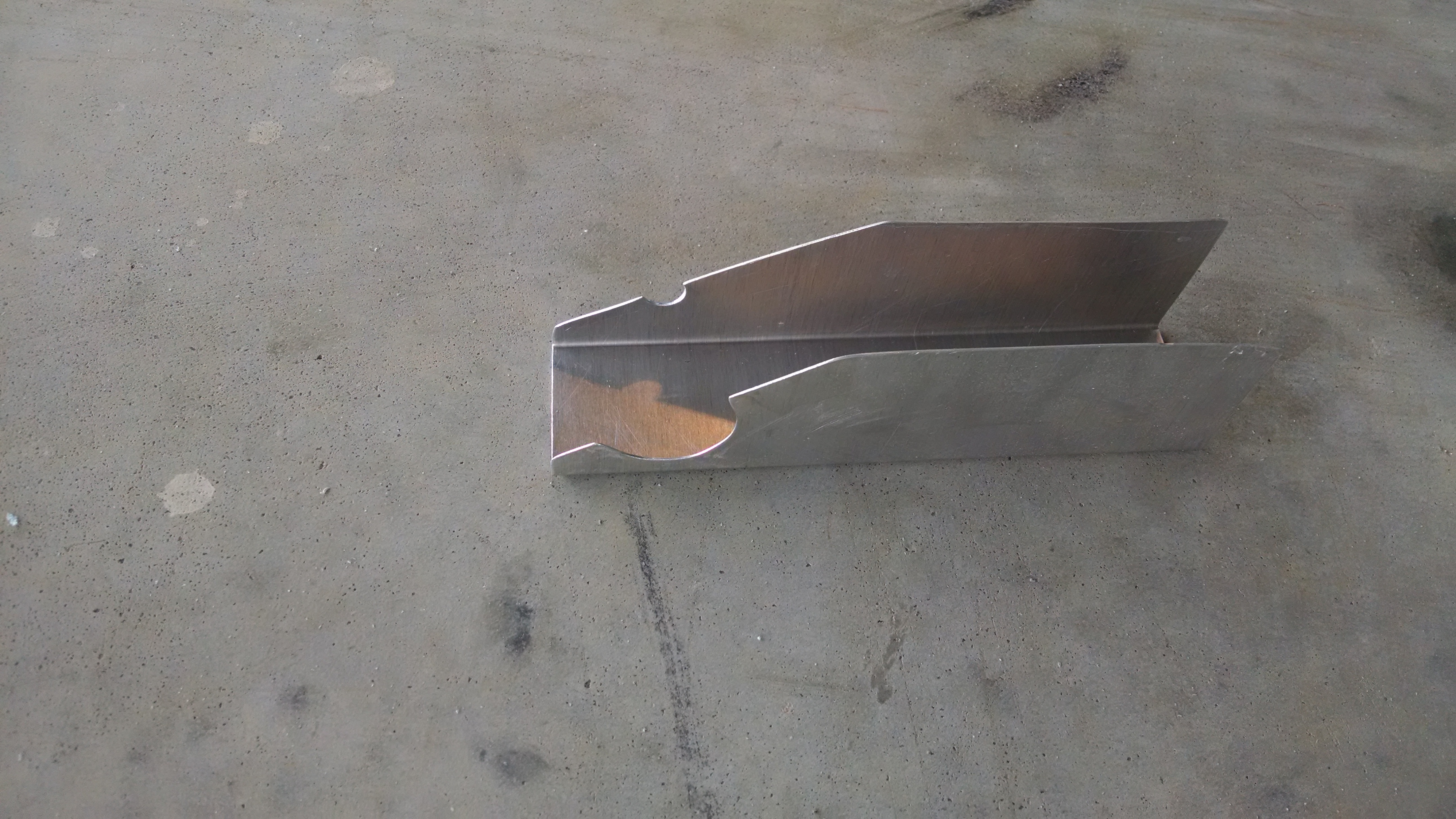
One of the frustrating things is that while loosening the fittings, fuel would squirt, or trickle out around the fittings. Because of the shape of the fuselage, the fuel would pool on the flange.  I tried my form-a-funnel and every other trick that I could think of to no avail.

So I decided to build a couple Fuel Filter Removal Diverters (Patent Pending).

2016-02-29 IMG_20160229_1224432222016-02-29 IMG_20160229_122430569

13.99 Electrical System Diagram

This entry is part 63 of 67 in the series 13 - Electrical / Instruments

I’ve received some requests for my electrical system specifics. So I have exported the diagrams to a PDF file. This file includes some things that aren’t specifically “electrical” such as the graphics for the switch panels and instrument panel layout.

621CM Electrical System

If you have any questions about my electrical system, please don’t hesitate to ask.

I will offer up one opinion: The Vertical Power VPX-Pro is probably one of the smartest choices I’ve made with respect to product selection. Here is a very short list of some of the features that have me grinning like a kid at Christmas:

  • Wiring is significantly easier than it would have been had I used traditional circuit breakers.
  • You can see exactly how much current individual devices are drawing.
  • Changes (and no matter how much you plan, there are always changes) are much easier to implement.
  • Built in starter switch lock out.  When the engine is running, you started button is disabled.
  • Built in landing light wig-wag which is activated by a pre-set speed.  (the downside is now I have a Xevision wig-wag module that I don’t need)
  • Variable speed pitch trim.
  • Support for backup EFIS battery.
  • Support for dual alternators.

Any questions I submitted to Vertical Power were responded to in usually less than 4 hours.  Many times by Marc Ausman himself. But a few years ago Vertical Power was acquired by Astronics.  I was worried that the support would suffer. But that has not turned out to be the case.  Responses are just as quick and helpful as before.

But in the spirit of full disclosure, there are some downsides.  The biggest for me is the number of available circuits.  There are only about 23 user definable circuits. That sounds like a lot, but once you start adding up all your devices, you come up short real fast (I have about 32 individual devices not including the accessory power ports). So you have to take one circuit and split it off and use fuses to support more devices. For example, I have one of the VPX circuits driving the Overhead Lights, Panel lights, Map Light, and Warning Lights. Because each of these are independently dimmed, each leg had to be protected by a fuse.

15-1-6 Weatherstripping

This entry is part 5 of 9 in the series 15 - Interior

I think the factory supplied weatherstripping leaves a bit to be desired as far as sealing without creating problems closing the doors.  The problem is when my door openings were created, the gap varies quite a bit.  Me and Malcolm tried to figure out a way to make the space consistent, but it would have been a ton of work.

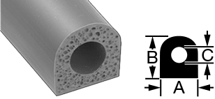
So I picked up a couple sizes of very compressible weatherstripping from McMaster-Carr.

93085k11c2-style12-j05l

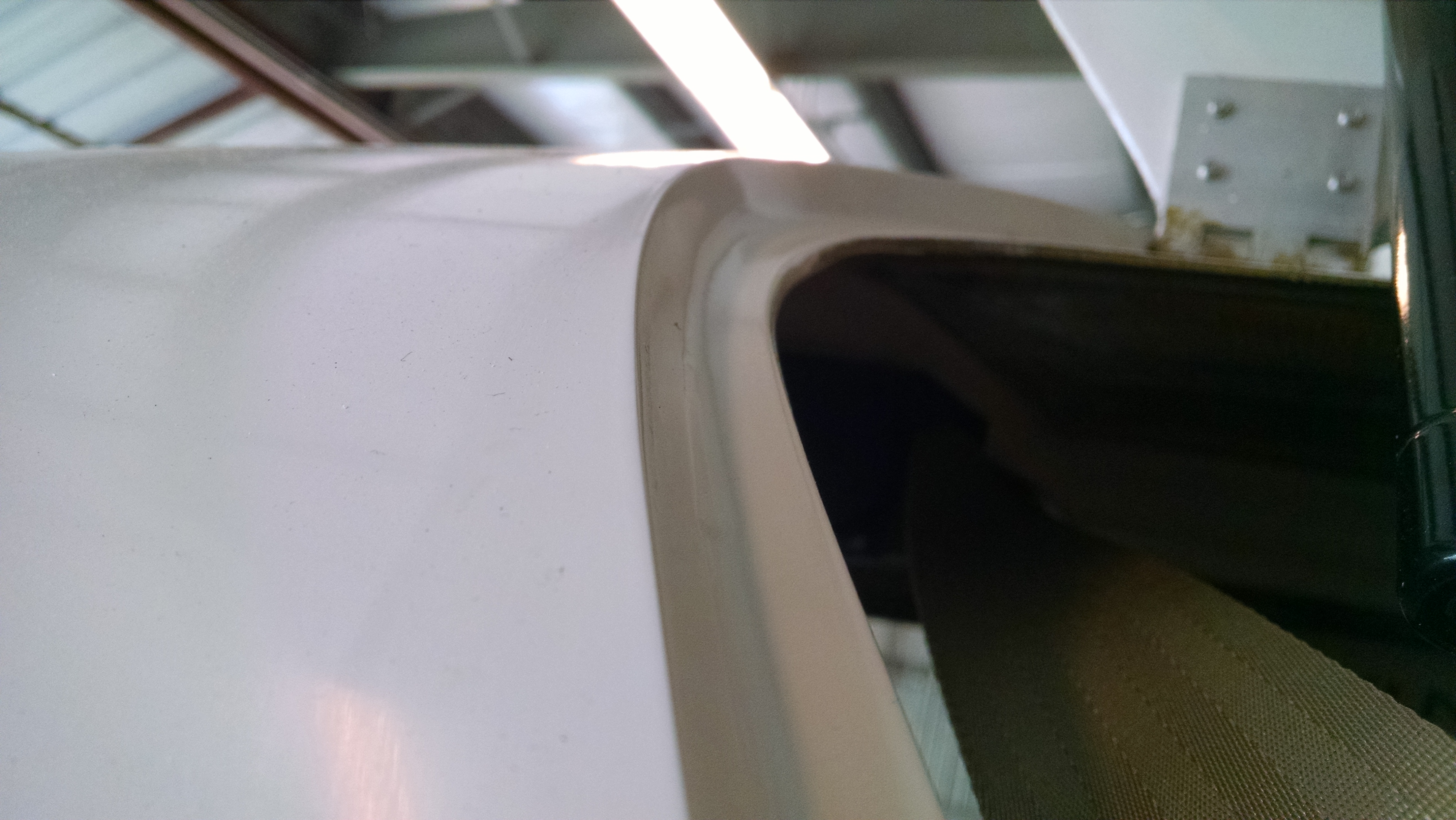
After testing a couple different sizes, I determined that the 1/2″ thick material was perfect. It made contact all around the door and didn’t create any problems closing the doors.

I attached it to the fuselage so that when opening the door, water wouldn’t run into the cabin.

2016-01-27 IMG_20160127_115633926 2016-01-27 IMG_20160127_121028760

8.1.2 – Wheel Alignment, Part II

This entry is part 7 of 8 in the series 08 - Wheels / Axles

Once I got the new GPS installed, then discovered the fuel system had a bunch of contaminant in it and flushed it out, I wanted to run the engine for at least an hour to verify the fuel system was clean. So I did some low and high speed taxi runs. During those runs, I noticed a shimmy. So I decided to check the alignment.

What I discovered was that I had some negative camber on one wheel and the toe-in was non-existent on the right wheel (actually is had significant toe-out). Read farther down to see how I do a solo alignment check.

Now when me and Malcolm were doing the alignment we had a hell of a time getting a consistent result on the right side. The problem was the gear leg was not flat. So depending on the order we tightened the bolts, the torque value, phase of the moon and so on, we would get different toe-in results. The fix I came up with was to use an epoxy/cabo mix to create a thin, flat pad on the gear leg. Once that was done, we determined that a regular flat washer on the rear bolts gave us the necessary 1″ toe in.

What ended up happening is that the once the brakes heat up, the pad became soft enough so that the washer became embedded into the pad. This may not have been a problem had I used a) large area washers cut down and/or b) placed the washers between the garolite and the axle pad.

IMG_20151230_121114209

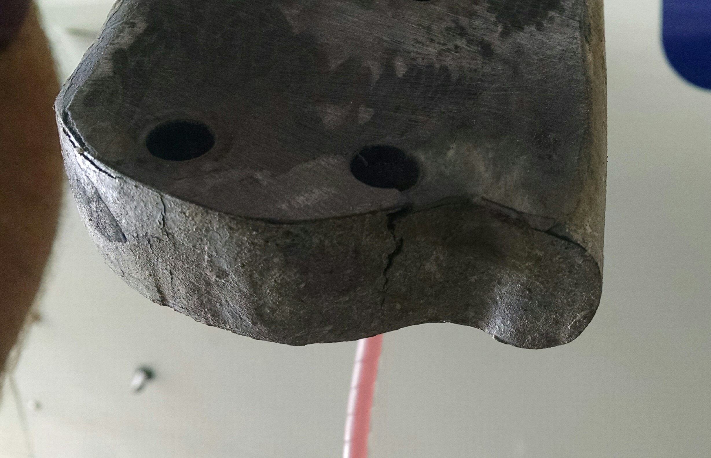
I used my large Permagrit board to remove and flatten the bottom of the gear leg without removing too much of the carbon fiber. While doing that, I discovered some rather concerning cracks from the bottom/front holes to the lower edge of the gear leg.

_20151230_123121

When I was drilling these holes, I thought they were awful close to the edge, but there’s no way to mount the brakes otherwise. I checked with Scott and he confirmed that the cracks are not unusual given the location.  Good thing there’s three other bolts!

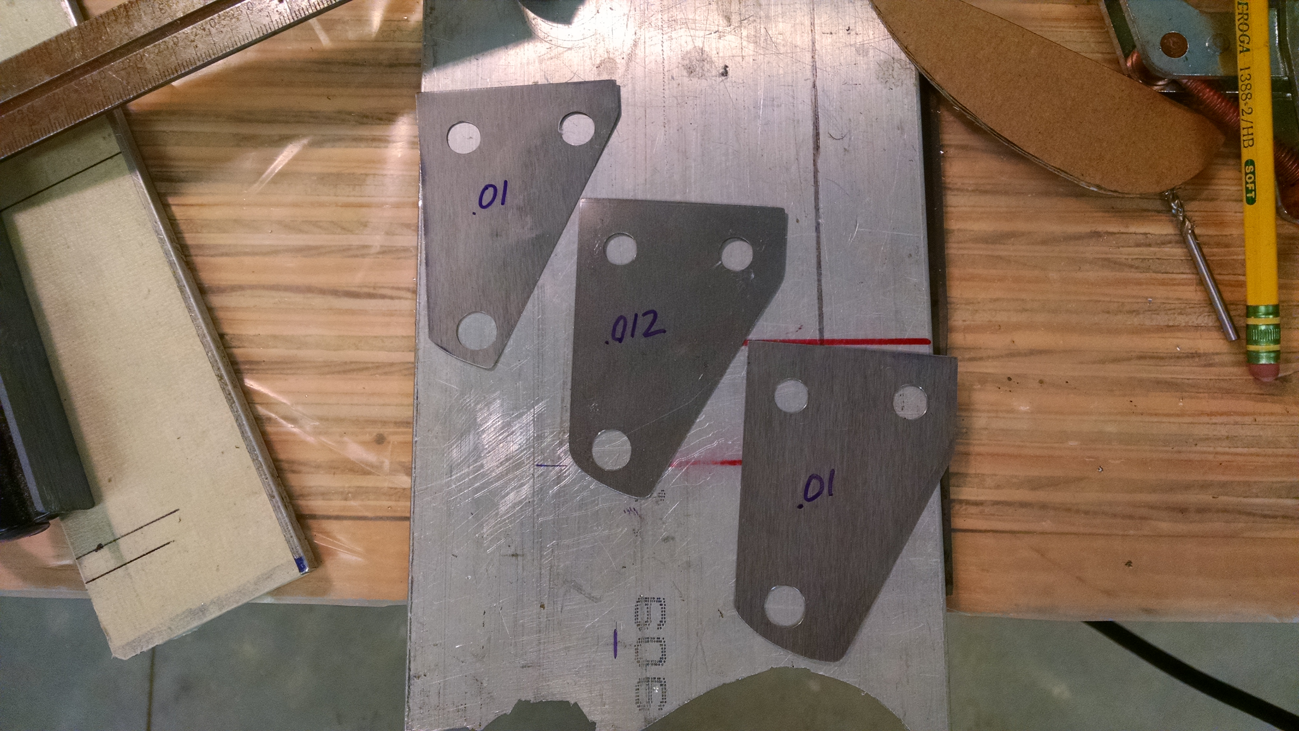
I ordered some steel shim stock from McMaster-Carr for $19. I could have used aluminum that I had laying around but I wanted something that didn’t conduct heat as quickly.

So I put everything back together and checked the toe-in. The general rule is that .010″ of shim will change the toe-in by 1″. But there’s no guidance on adjusting camber.

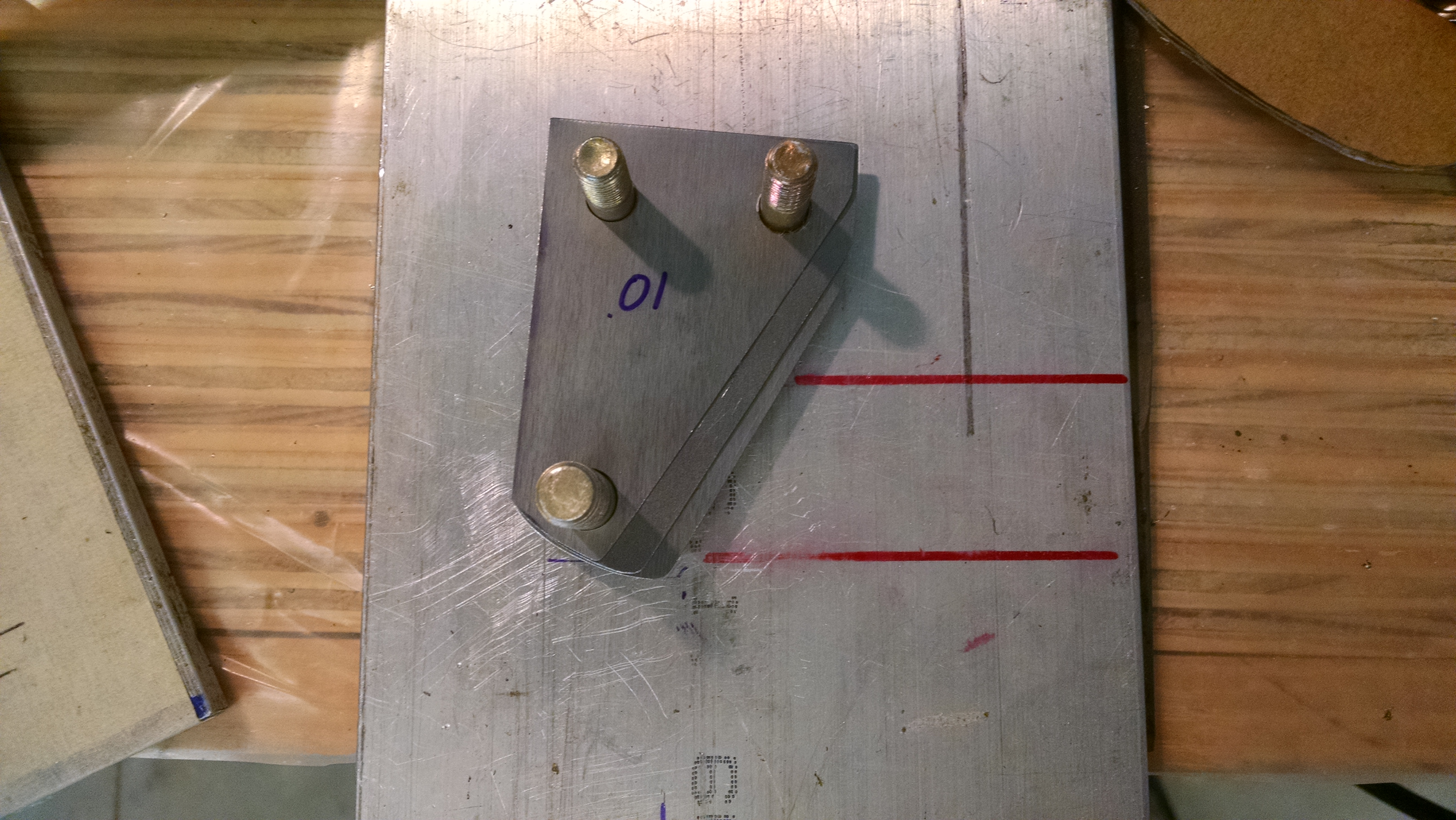
I started with .032″ of shims on the top (to eliminate the negative camber) and rear (to get some toe-in.

IMG_20160109_112330011 IMG_20160109_112402407

Because of the geometry, I also made some wedge shims for the top/rear.

But when I put everything back together, I getting the same behavior as before where the resulting readings where all over the place. So I decided to eliminate the space in the center.

IMG_20160109_152753461

Once I did that, I was getting consistent results. Then I just kept adding shims to the top and rear until I got neutral camber and 1″ of toe-in.  It took a few days because at first I was re-measuring everything after every change. Then I got it figured out so that it only took a few moments of positioning (you have to roll the airplane back 10′ and then forward 5-6′ to get the gear properly loaded and positioned.

Checking the wheel alignment solo.

When Malcolm and I were doing the alignment the first time, it was pretty quick because with two people, it’s easy.  Not so much with one person.

Here’s the sequence:

  1. Get the main gear properly loaded and positioned. This is done by rolling the aircraft forward at least 5′. Because of the toe-in, this will move the wheels towards the centerline.
  2. Establish the centerline. Take some masking tape a place on the floor directly beneath the nose and the center of the prop (or spinner). Drop a plumb-bob from the nose and prop center and place a mark on the floor.
  3. Using a string (or laser) connect the mark on the floor at the nose with the mark and the tail. This is your centerline. Now the nose wheel is in the way for this step. There are two workarounds: a) raise the nose and put two small wood blocks on either side of the nose wheel leaving a space for the string.  b) make a mark 3″ to the right (or left) of the actual nose and tail marks. When you do this, you will have to adjust the next step 3″ to identify the centerline.
  4. Place a piece of masking tape about 7″ forward of the main gear axles and mark the centerline.
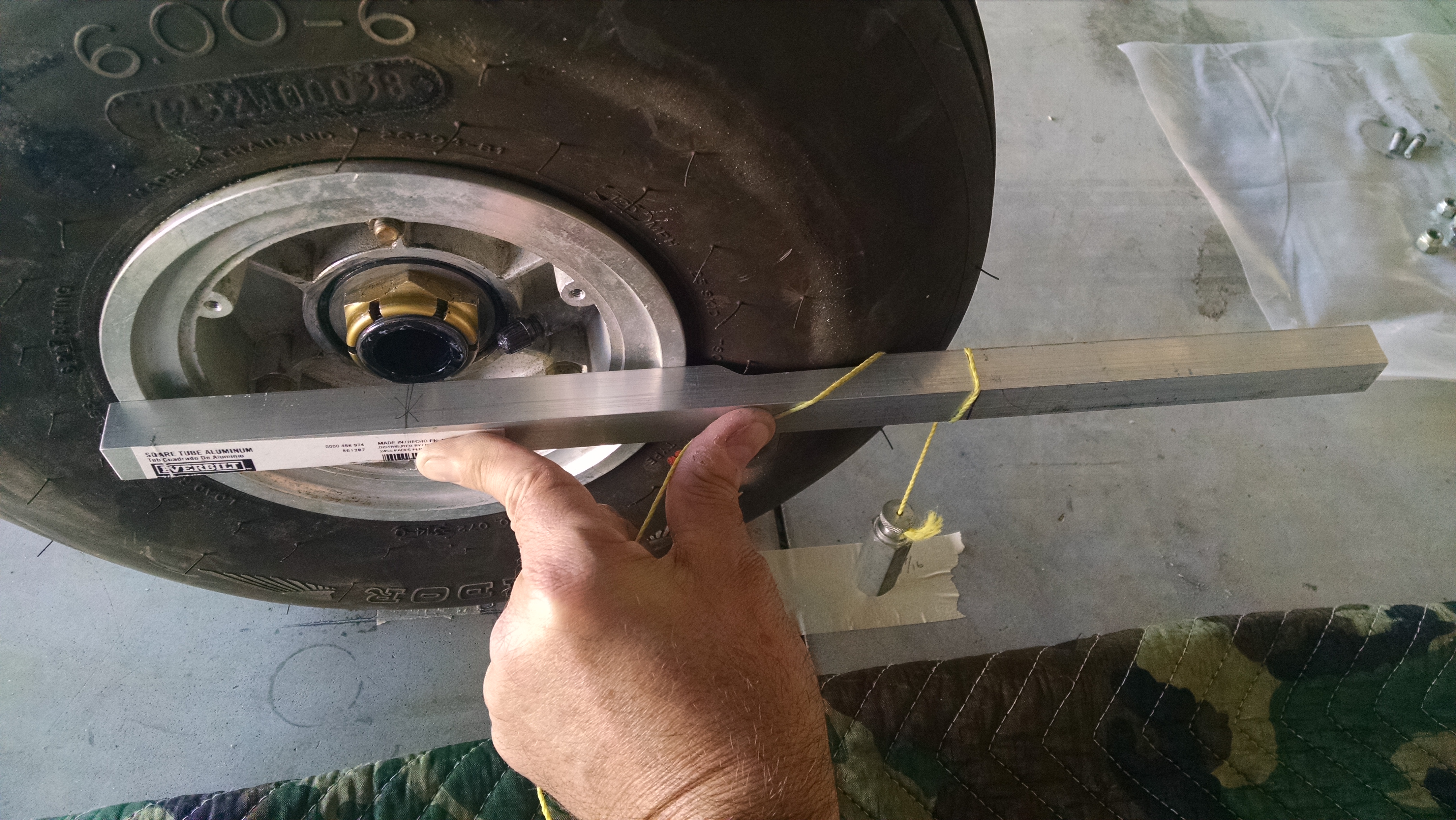
  5. Mark the location of the outside of the wheel (not the tire) 7″ forward of the center of the axle. There are a couple different tricks to accomplish this. I used a piece of scrap 1″ square stock with a notch for the tire. Then using a plumb-bob, place a mark the floor (actually, the masking tape on the floor). Do this for both wheels. IMG_20160112_132830544
  6. Measure the distance from each wheel to the centerline mark and write this down. Do not be surprised if the two numbers are not identical.
    IMG_20160112_132844275
  7. Measure to the left and right of the nose mark and place marks on the floor that correspond to the distances you recorded in step 6. I placed a strip of tape marking a one inch intervals.
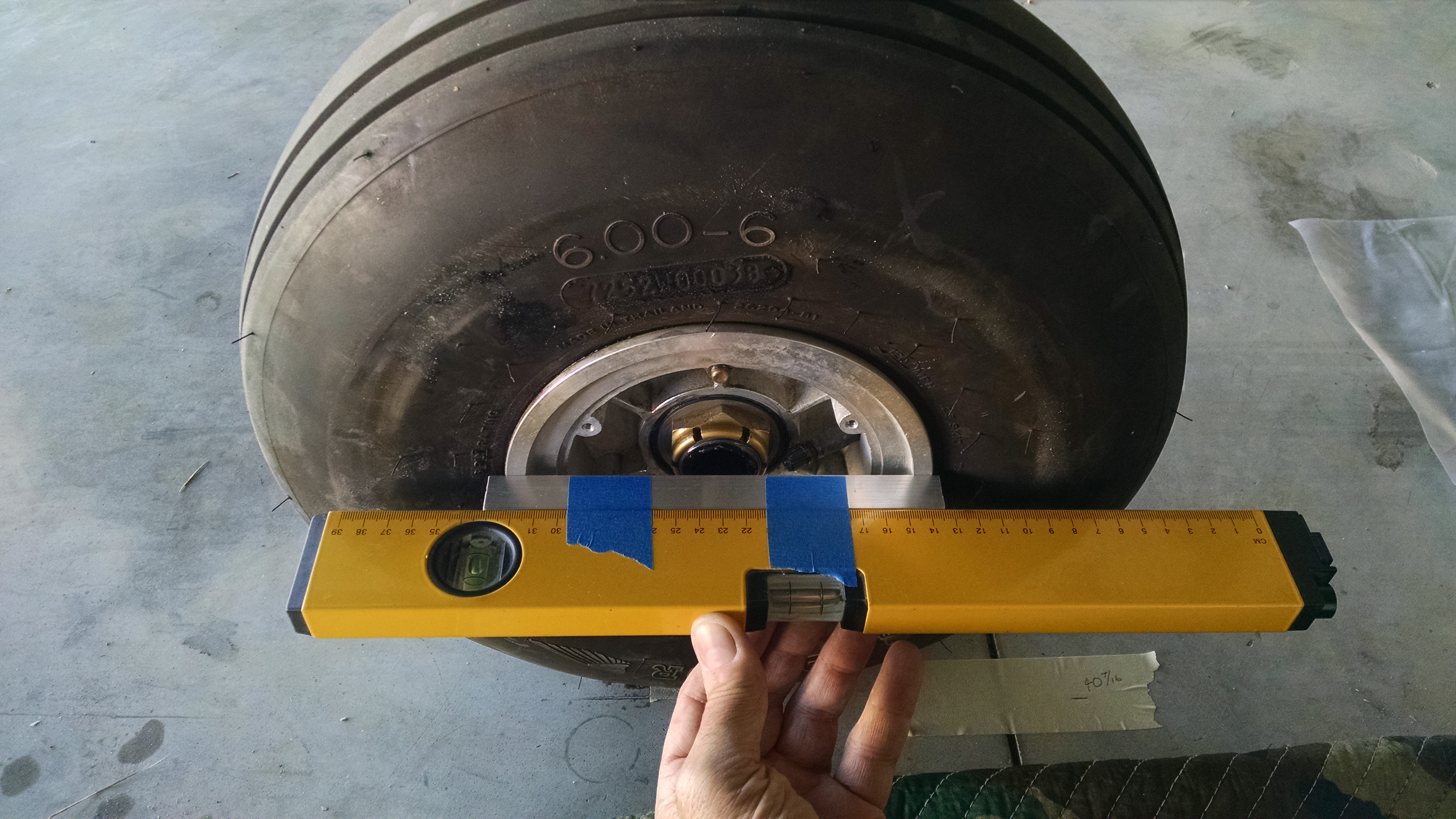
  8. Now we have to project a line from the wheels to the front. The manual uses long aluminum I or box beams and deflating the tires so the aluminum will contact the wheel and not the tire. What I did was to take a piece of 1″ square aluminum stock to it that was just long enough to span the wheel rim and tape that to my laser level. Now I can shoot the laser up front.
    IMG_20160112_133456757
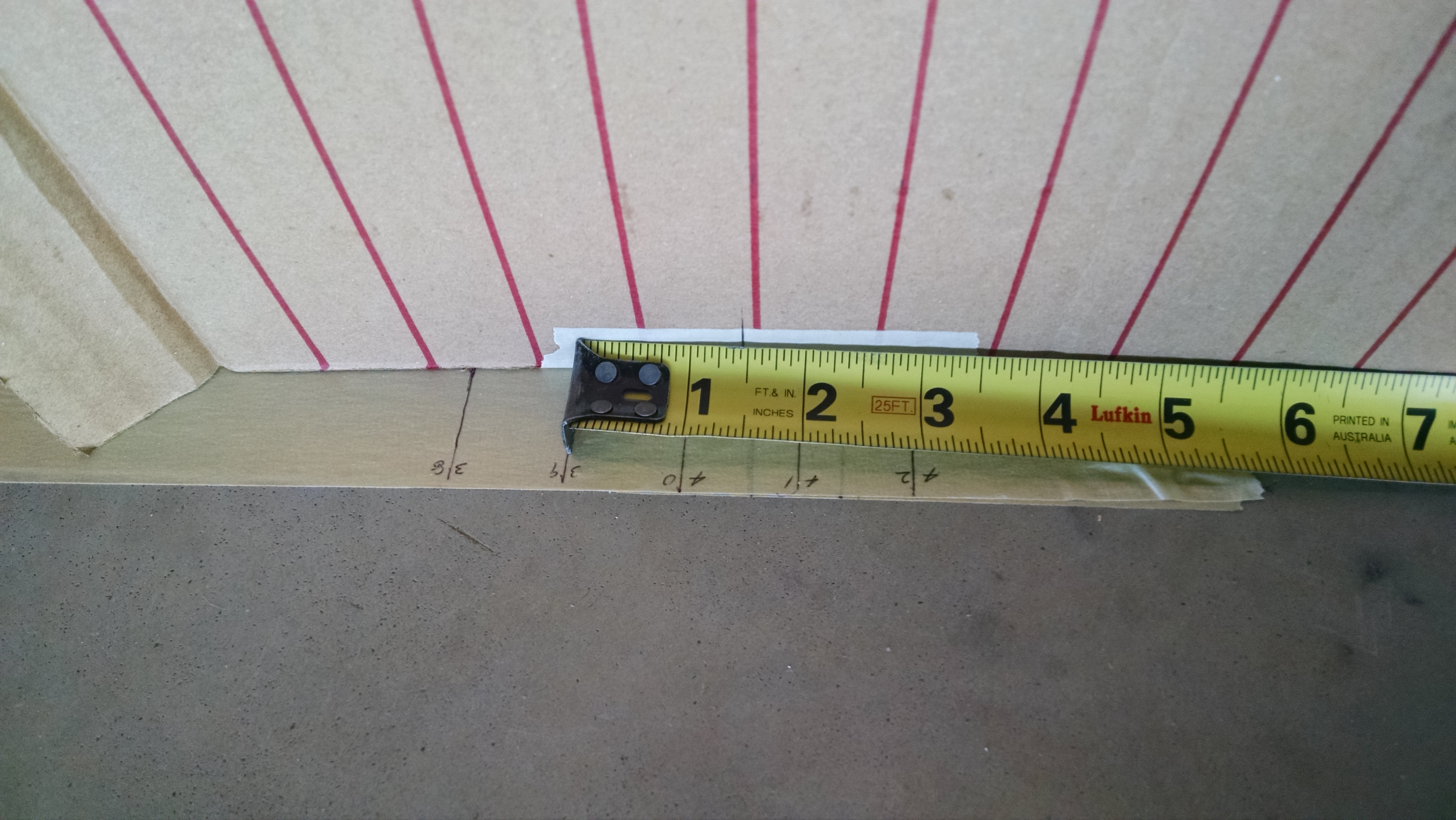
  9. If there was another person, they could use a tape measure to see if the laser dot was 1″ inside of the mark on the floor. Since I was alone, I made a target out of cardboard. I drew vertical lines that were 1″ apart. Then I placed a mark on the cardboard 1.15″ inside of the zero line (that is the distance from the 1″ bottom of the 1″ square stock to the laser. Place the target on the floor so that the reference mark is on the spot on the floor and now you can shoot the laser at it and see if you have the correct toe-in. My laser also has a flat line option so I can use that to check the camber as well. But that line is rather dim so I have to make the hangar somewhat dark to see it well.
    IMG_20160112_133309577IMG_20160112_133341057
  10. Final, successful results
    IMG_20160113_170945545 IMG_20160113_170852928

GPS Replacement

This entry is part 61 of 67 in the series 13 - Electrical / Instruments

Long ago when I began this project, I decided on a glass panel. At the time, there were a number of vendors offering EFIS (Electronic Flight Information System) solutions. I decided on the Grand Rapids Technology product.  At the time, they had the HX EFIS products and an Engine Analyzer.

So I was going to have a single screen on each side of the instrument panel with the “radio stack” in the middle. This stack would have the communications/navigation radios, audio panel and GPS.

Once I started building, they released the HXr EFIS displays.  These displays support “remote” devices.  Which means the radios and audio panel are controlled through the EFIS and do not have to be located on the instrument panel. There was no IFR GPS option though so I was going to go with a Garmin 400W WAAS GPS mounted on the instrument panel.

Then a couple years ago I heard that GRT had an IFR GPS in the works. I asked them about it and was told that it was “in development” but would be ready in a year. Since I was still a couple years from needing it, I decided to go that route.

When I was time to order all the avionics equipment I placed the order.  But the GPS still wasn’t ready. So I started installing the avionics and left a spot available for the GPS.  In October of last year, I finally received the GPS!  Hooked everything up and I was good to go.

Except that I realized that I had never loaded the GPS database.  When I asked for instructions about doing that I learned that the software for the EFIS wasn’t finished. I was told November or December.

But I didn’t want to run version 1.0 software while shooting an instrument approach to minimums.

So I returned the GPS and began looking for a used Garmin 400w.

One of the glitches with this particular operation is that when I was laying everything out, I didn’t allow for a 12″ deep, panel mount GPS.  That means I have to do some rearranging.

2015-07-06 IMG_20150706_081241770

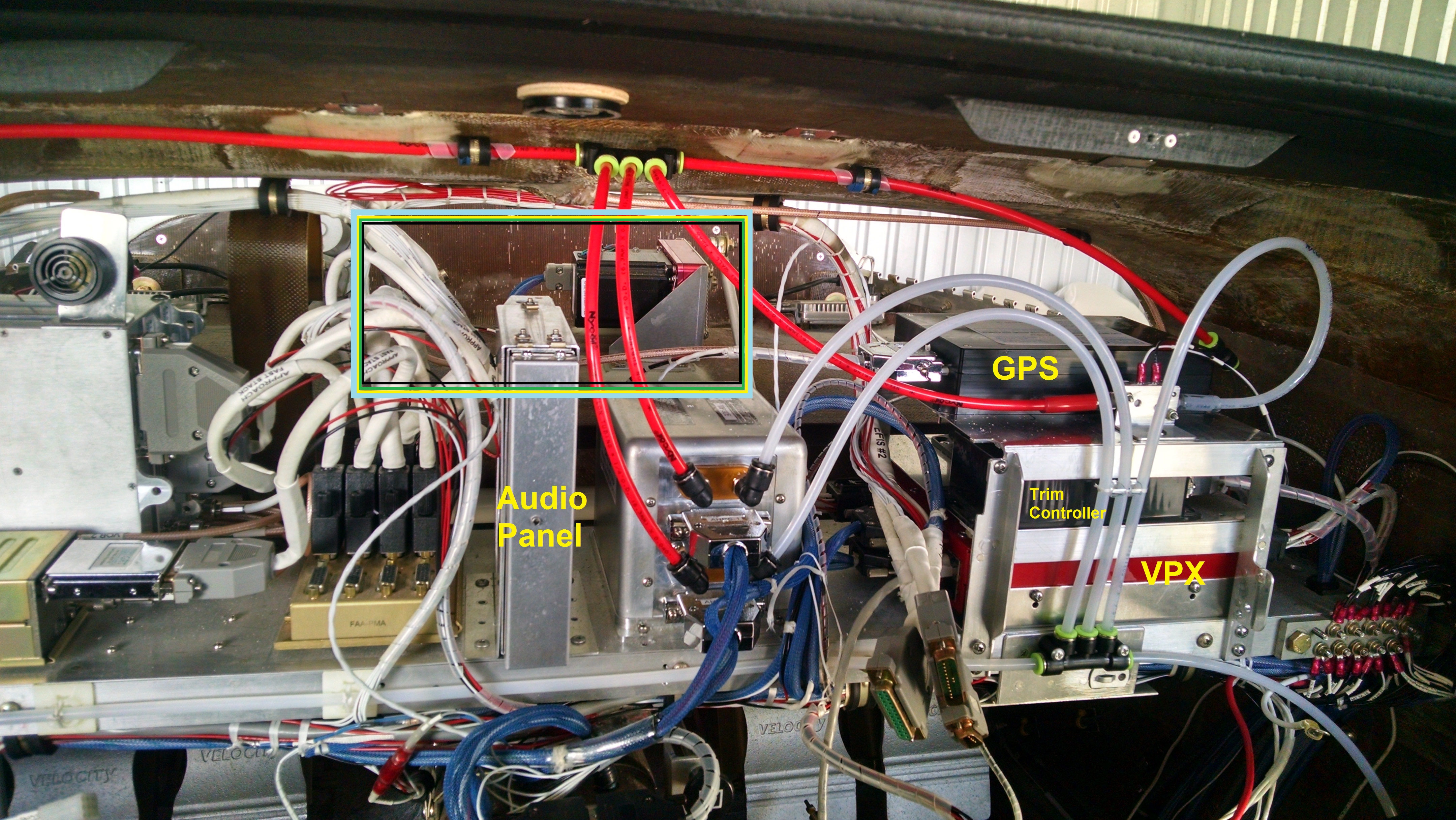
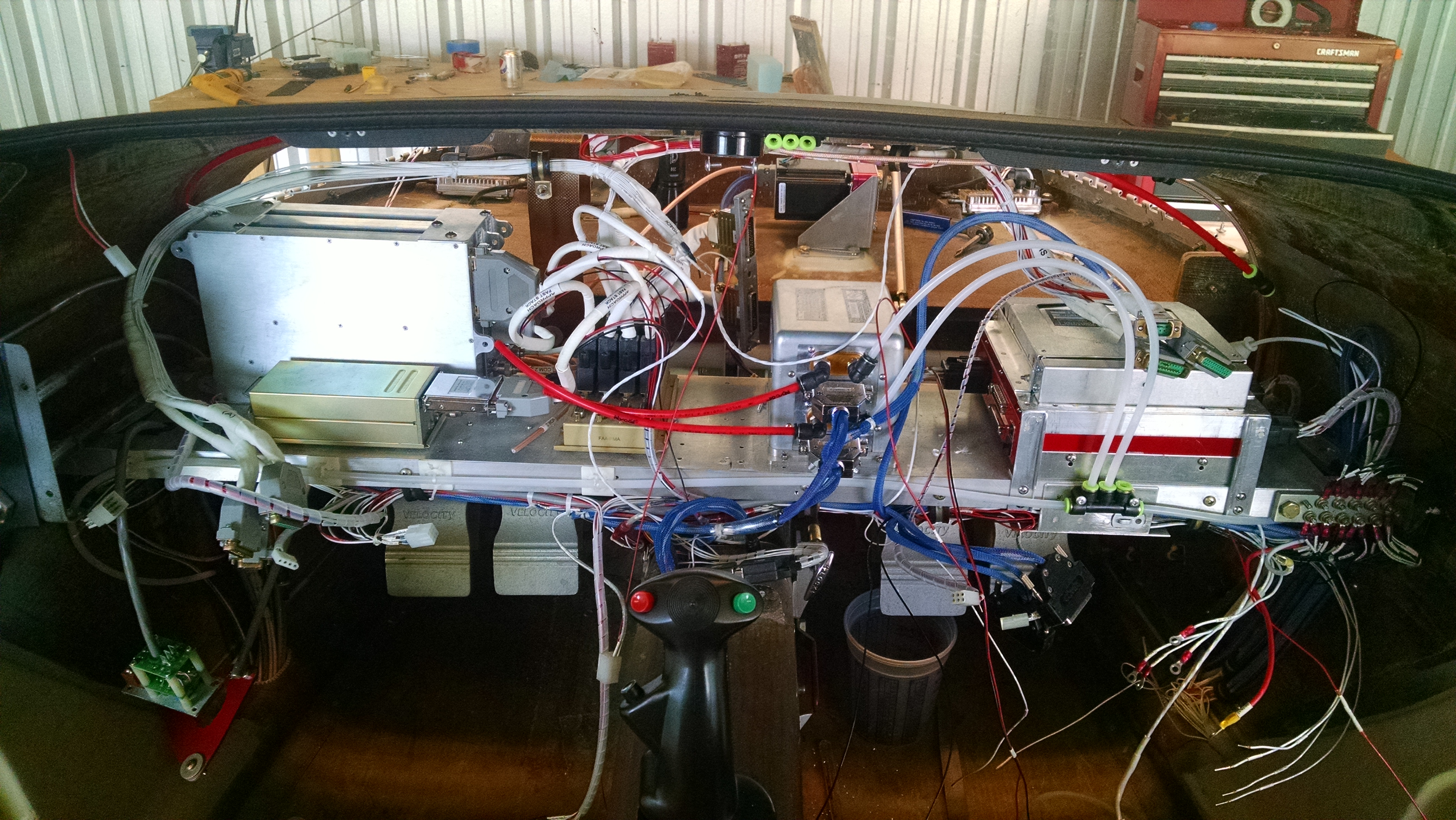
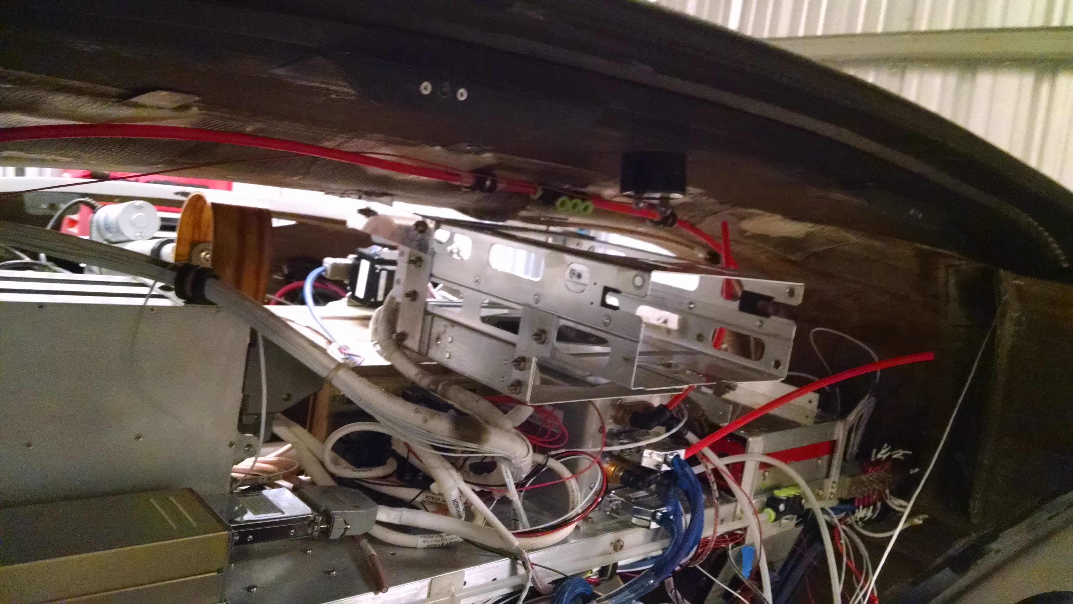
This is the avionics shelf behind the instrument panel. The multi-color rectangle is where I figure the panel mount GPS will be.

Obviously the audio panel is going to have to be moved. I think the cables from the hub (white cables to the left of the audio panel) will be able to be pushed down.  The pitot lines (red tubing) will have to be relocated as well.

My first plan was to remove the top shelf which currently holds the GPS, remove the trim controller and mount the audio panel just above With the audio panel out of the way, then I would just have to re-route the pitot tubes.

2015-10-30 IMG_20151030_144443349

So here I’ve removed the old GPS, trim controller and power stabilizer (more on that later) and relocated the audio panel above the VPX.

But there’s a problem… The audio panel cables aren’t long enough to reach to the new location.  Since I was going to need cables for the new GPS, I got in touch with Tim Hass at Approach Stack to ask if I could get an extension cable for the audio panel.  Normally, I would just replace it with a new, longer cable but the existing cable has wires running to all the headset jacks, control stick, right switch panel, etc. and I didn’t want to have to pull and reconnect all those connections.

While I was talking to Tim, I told him that I was looking for a used 400w but not having much luck and that if he knew of one to let me know. He said that he had a brand new Garmin GTN625 that he could sell me. This is basically the new, improved replacement for the discontinued 400w.  And the price was just a little more than I was finding for the old units. So I told him “sold”!

A while later, a box showed up with the new GPS, mounting hardware, cables and my new audio panel extension cables.

Uh-Oh…

The audio panel cables are huge.  They are thick and they don’t bend very much. Add in the connectors and I was having trouble routing the cables so that they didn’t interfere with important stuff. So I set that problem aside and started working on getting the GPS mounted.

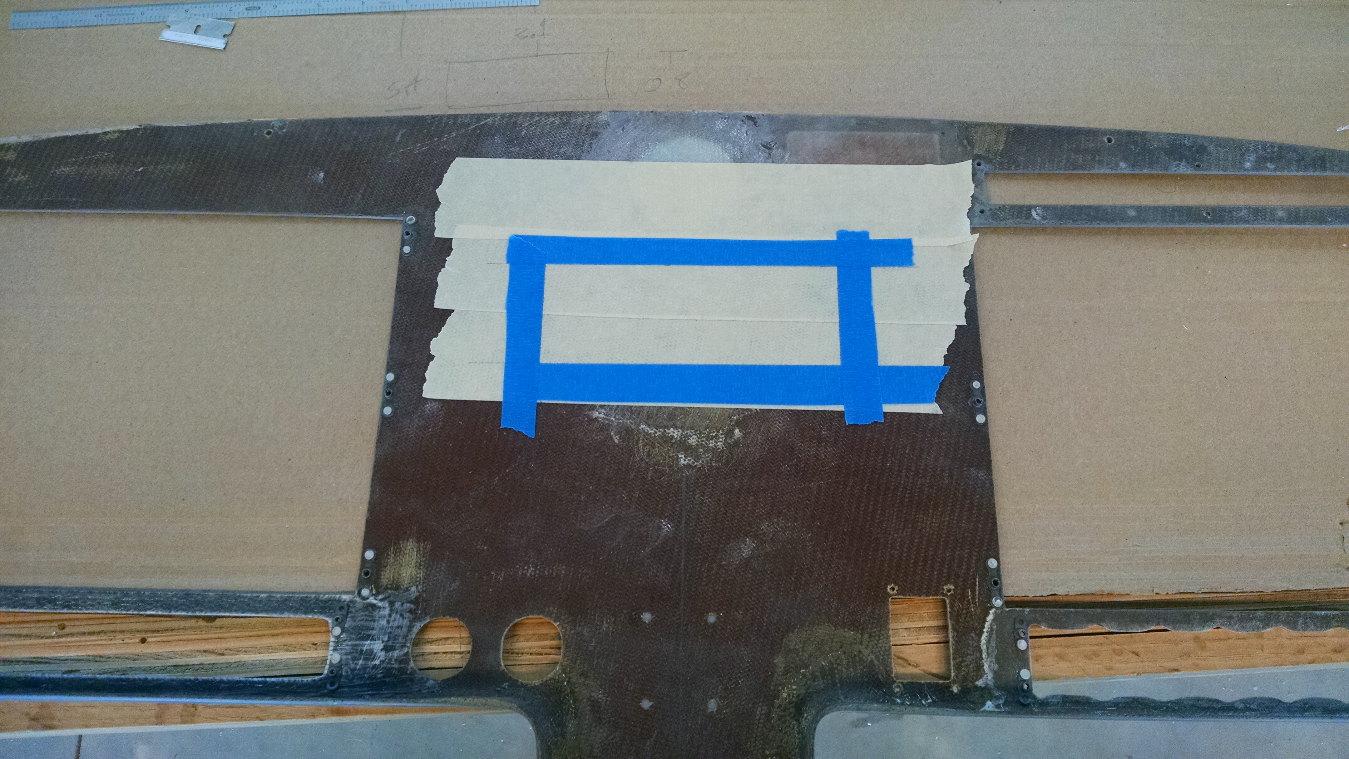
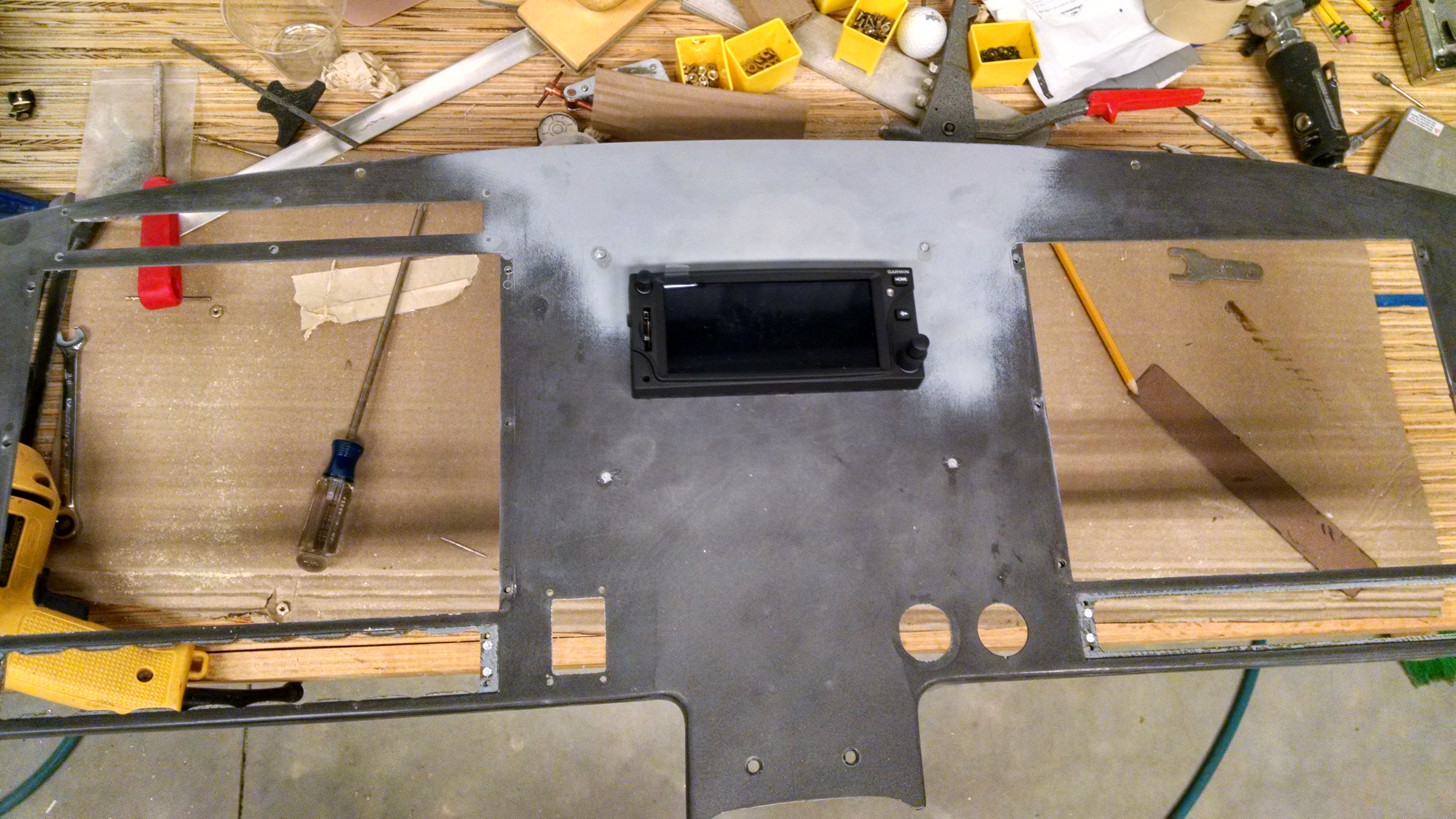
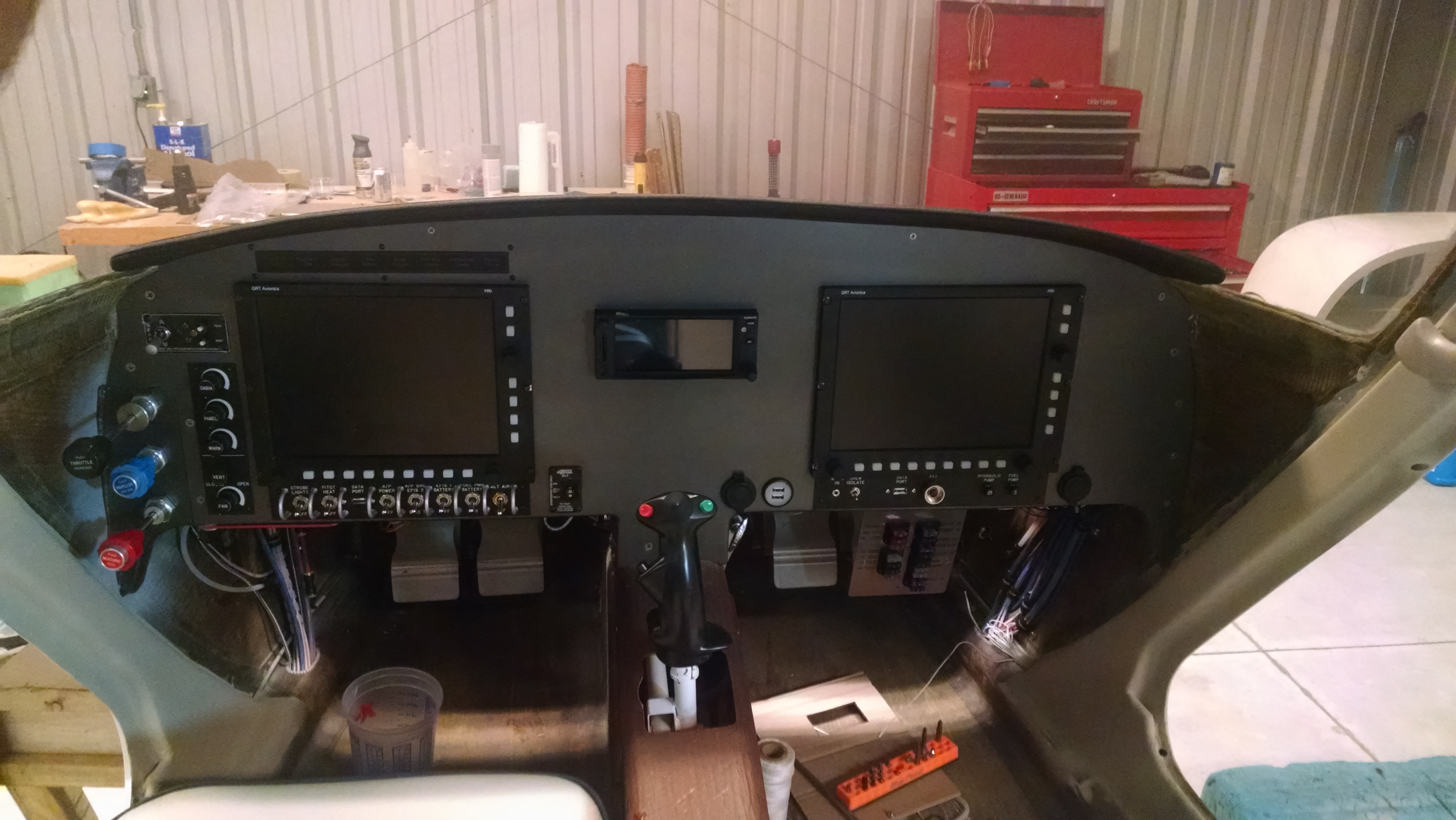
I decided to mount the GPS in the center of the panel directly between the two EFIS screens. But the compass was in the way.  Since I had to eliminate the power stabilizer, I needed to create a backup power source for the primary EFIS/AHRS/Magnetometer. That means I do not need a traditional whisky compass. But I do need to fill in the hole where the compass used to be. Once that was done, I had to determine how I would support the back to the GPS.

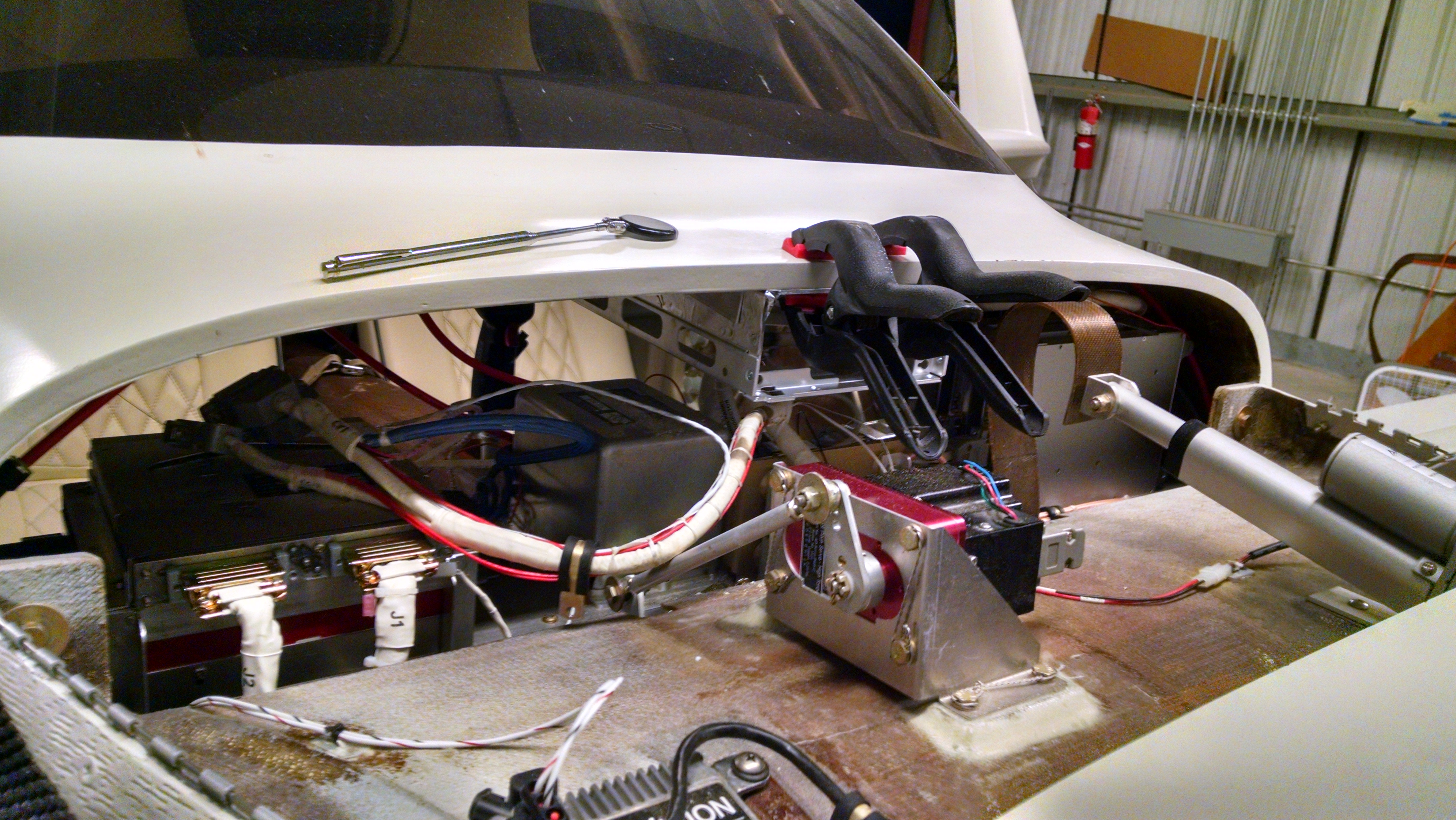
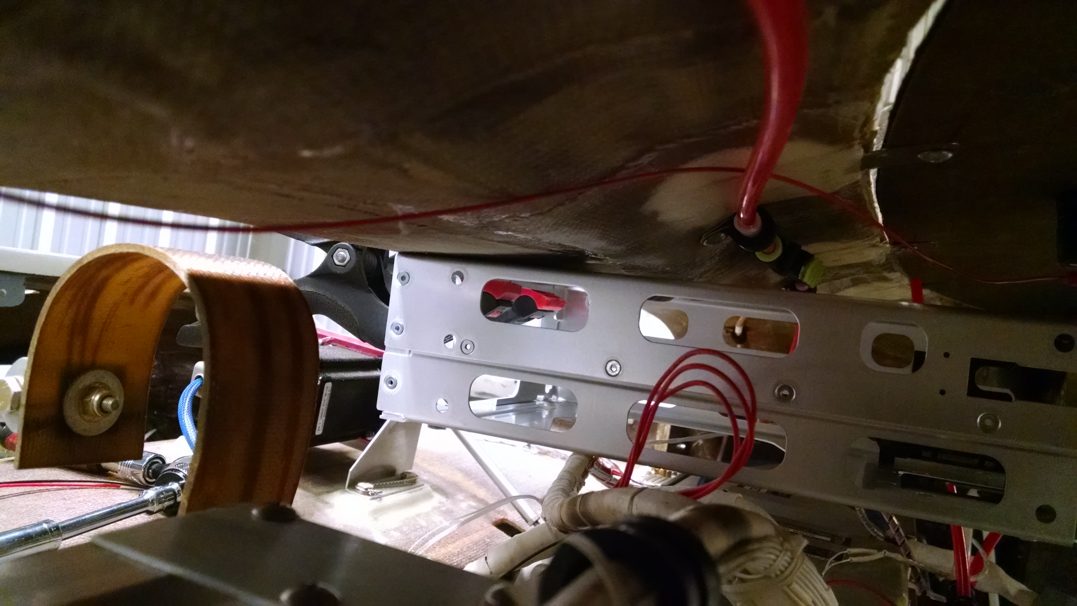
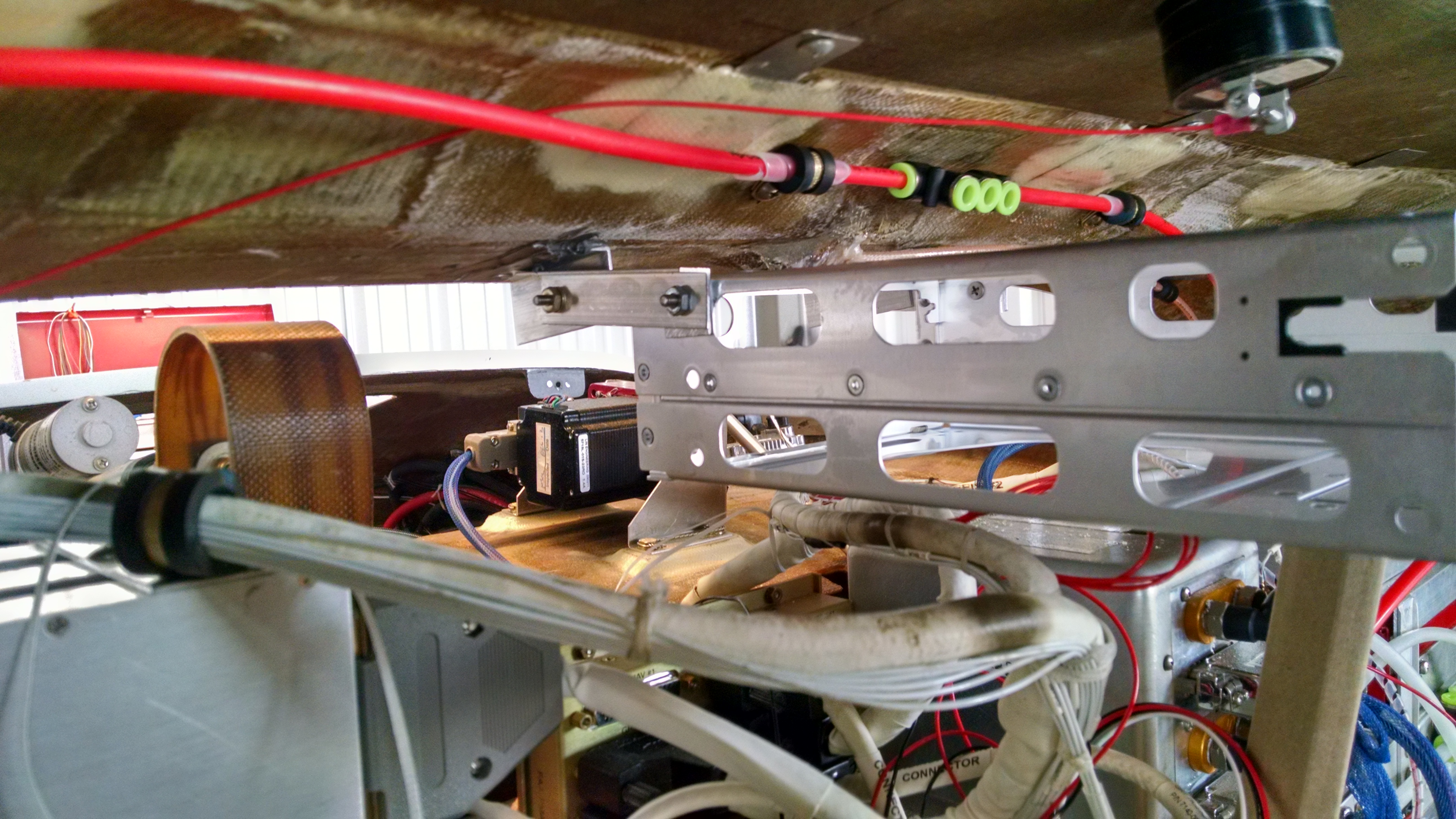
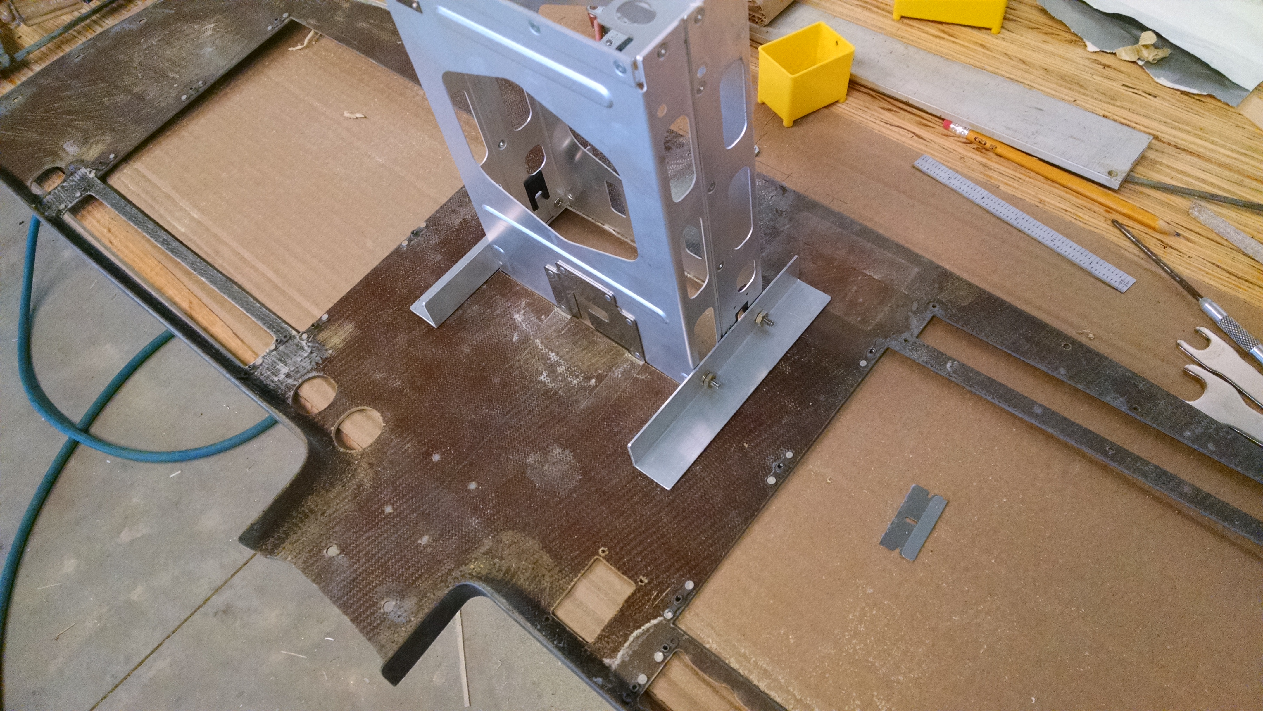
I decided to support it from above rather than build supports from the avionics shelf. So I located the center of the inside of the fuselage just aft of the canard opening. Then I used spring clamps to hold the GPS tray in place while a used structural adhesive and rivets to attach a pair of aluminum angle brackets using the tray as a guide.

2015-11-20 IMG_20151120_195439506_HDR2015-11-20 IMG_20151120_1729418392015-11-20 IMG_20151120_195421094

Once that cured, I made some short aluminum supports to allow the tray to sit farther forward so that it could reach the panel.

2015-11-21 IMG_20151121_141859601_HDR

Then I leveled the tray up and marked the panel where I would have to cut an opening for the GPS.

2015-11-21 IMG_20151121_141829788

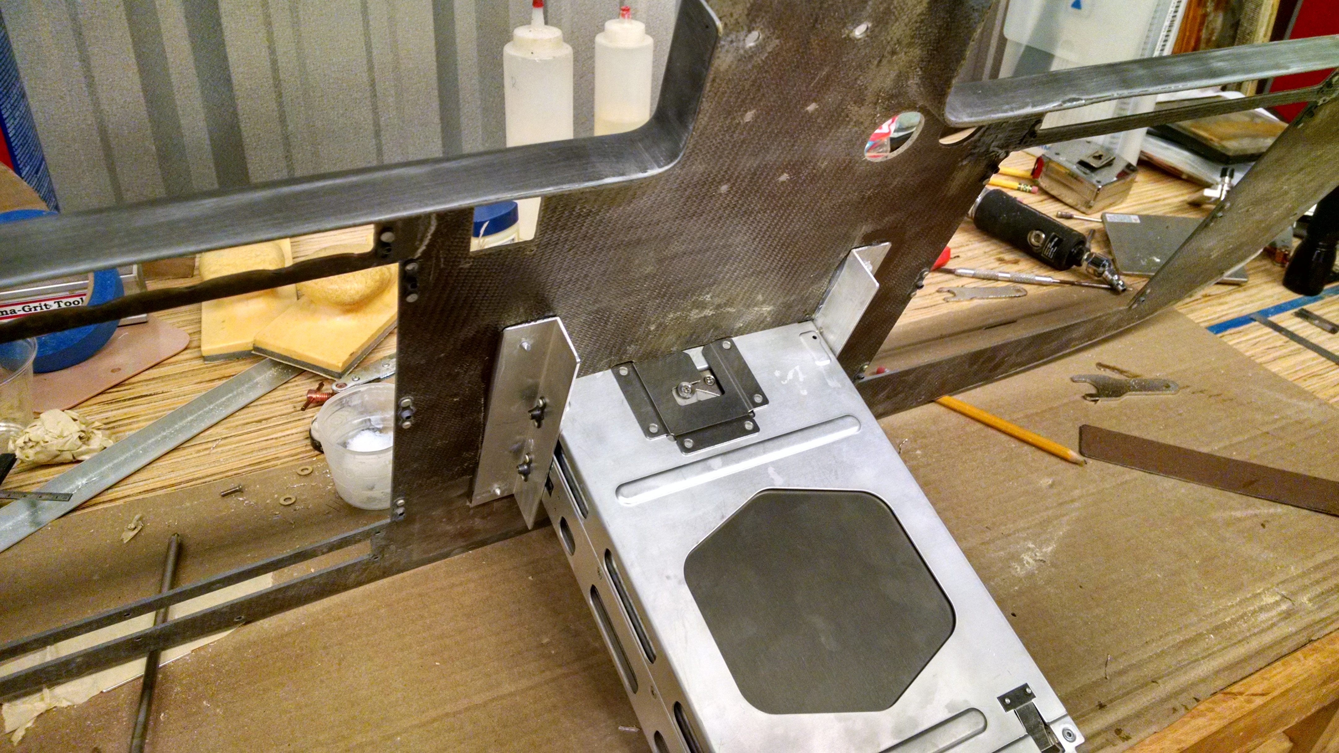
After I cut the opening (which took a while because I cut it small and gradually increased the size), I had to support the tray where is met the panel. I chose to bond a couple of aluminum angle brackets to the back of the panel.

2015-11-21 IMG_20151121_1558016482015-11-22 IMG_20151122_085633305_HDR

And then just to look at it with the GPS inserted.

2015-11-21 IMG_20151121_171559569_HDR2015-11-22 IMG_20151122_085614083_HDR

Then I removed the tray, mounted it to the rear support, put the instrument panel in and attached the tray to the panel brackets.

That’s when I discovered something; There’s enough room under the tray to fit the audio panel.  By placing it there, it would be almost in the same location as before so I wouldn’t need the extension cables (and the associated routing problems).

So I pulled the GPS tray out and built a drop-down support from the GPS tray.

2015-11-22 IMG_20151122_113138423

Then everything goes back in.

2015-11-22 IMG_20151122_150006747

I rotated the wiring hub so the cables weren’t pointing straight up.

The last task is rerouting the pitot-static lines. I used the heat gun to heat up the tubes and bend them.  I’ll redo this to make it prettier later.

2015-12-01 IMG_20151201_160126648 2015-12-01 IMG_20151201_160133405_HDR

Now it’s time to put everything back together and power it up.

2015-12-02 IMG_20151202_181834240 2015-12-03 IMG_20151203_144630140


Secondary EFIS Power

This entry is part 62 of 67 in the series 13 - Electrical / Instruments

Because I have an “all electric” instrument panel, there are some challenges. One of those is powering the basic instrumentation during engine start. When you hit the starter button, the battery gets loaded down and the output voltage can (and usually does) drop enough that the EFIS reboots. It takes the HXr about a minute to boot up. So for that first 60 seconds after starting the engine, all I’ve got for engine health is the “Low Oil Pressure” warning.
To resolve this, I installed the TCW Technologies Intelligent Power Stabilizer (IPS).  This small, lightweight box gets power from the battery and provided a constant 24 volts even when the input voltage drops to as low as 9 volts. It can only output 24 volts for a couple of seconds when the input power drops but that is sufficient to keep the EFIS up and running during engine start.  The HXr has three separate power inputs.  The primary power input is connected to the battery.  The secondary power input is connected to the IPS.

With the GPS swap requiring me to move things around, I had to eliminate the IPS. To keep the HXr powered up during engine start I will have to go with a backup battery.  I would have done this originally except that the optional backup battery is only available for 12v HXr’s. I looked for a 24v backup battery, but they were either too big or too expensive. This is what happens when you go with a 24v electrical system.

So I decided to think outside the box.

I call these “Barbie Batteries”.

2015-10-23 IMG_20151023_130822062

I found a store that sells “Scooter Batteries” for things like mobility scooter, small electric cars… You know, those little cars that parents get their little kids?

1914099

I found that while the 24v batteries were big and pricey, I could get a pair of small 12v batteries that were very affordable. The batteries I got were 5ah SLA (Sealed Lead Acid). By connecting them in series, I would get 24v, 5ah.  Not only would this power the primary EFIS, AHRS and magnetometer during engine start, it would also keep the devices powered for at least an hour if the main electrical system failed.  An added bonus is that since the Magnetometer and EFIS will have an independent power source, I can eliminate the compass in the panel.

The down side is that they weigh 3.5 pounds each. Once I’ve verified this works, I may look for some new, fancy, hi-tech, low-weight batteries.

As for where to put these, I decided to put them in the nose. I noticed when flying alone that I required quite a bit of nose-down trim for level flight. Seven pounds in the nose should help that.

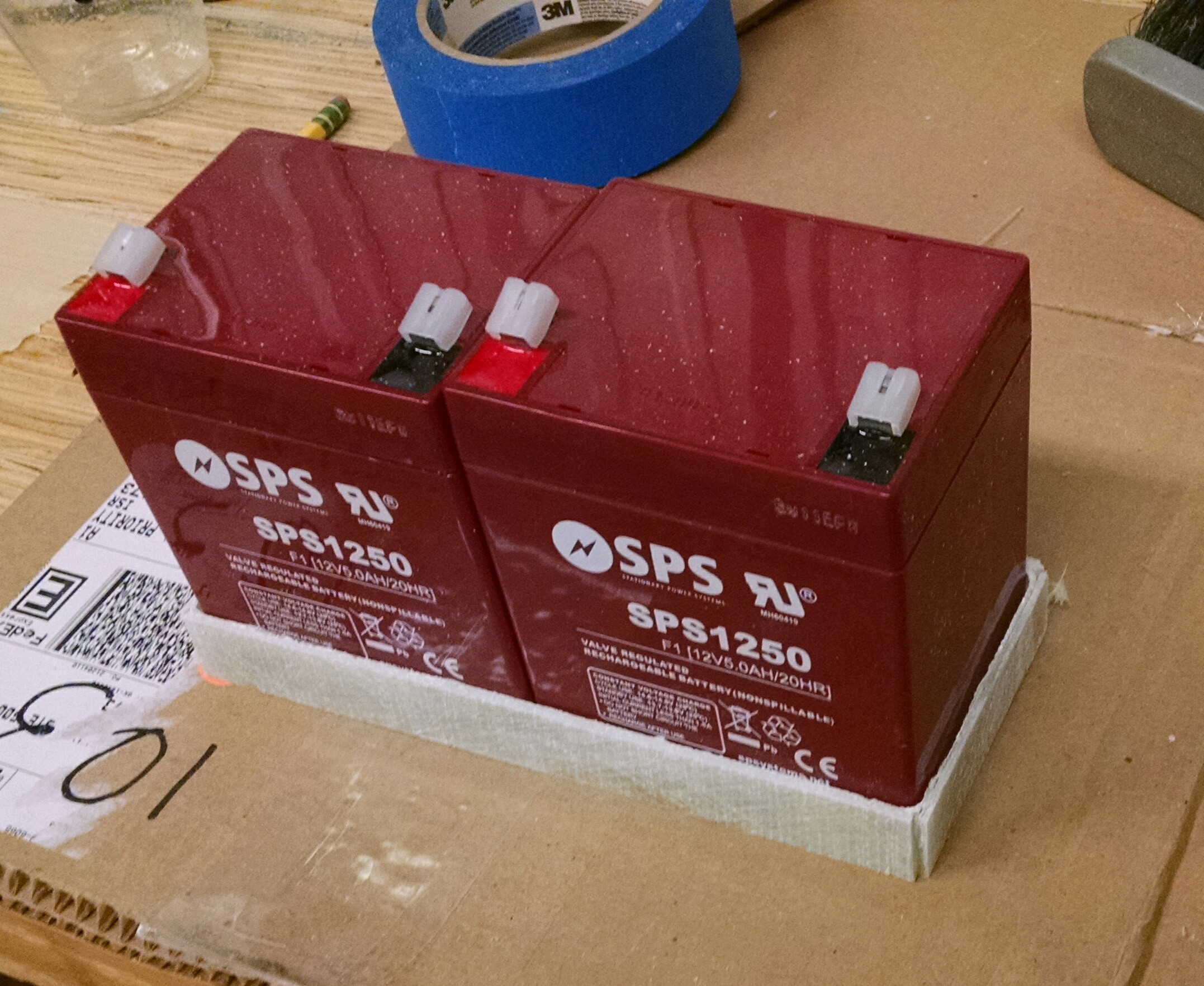
The first step is to make a tray for the batteries. So I wrapped the batteries with duct tape, took a piece of spare fiberglass, cut it to size and then applied some fiberglass strips to create the sides. Once it had cured, I removed the batteries and trimmed to size.

2015-10-30 _20151030_075211

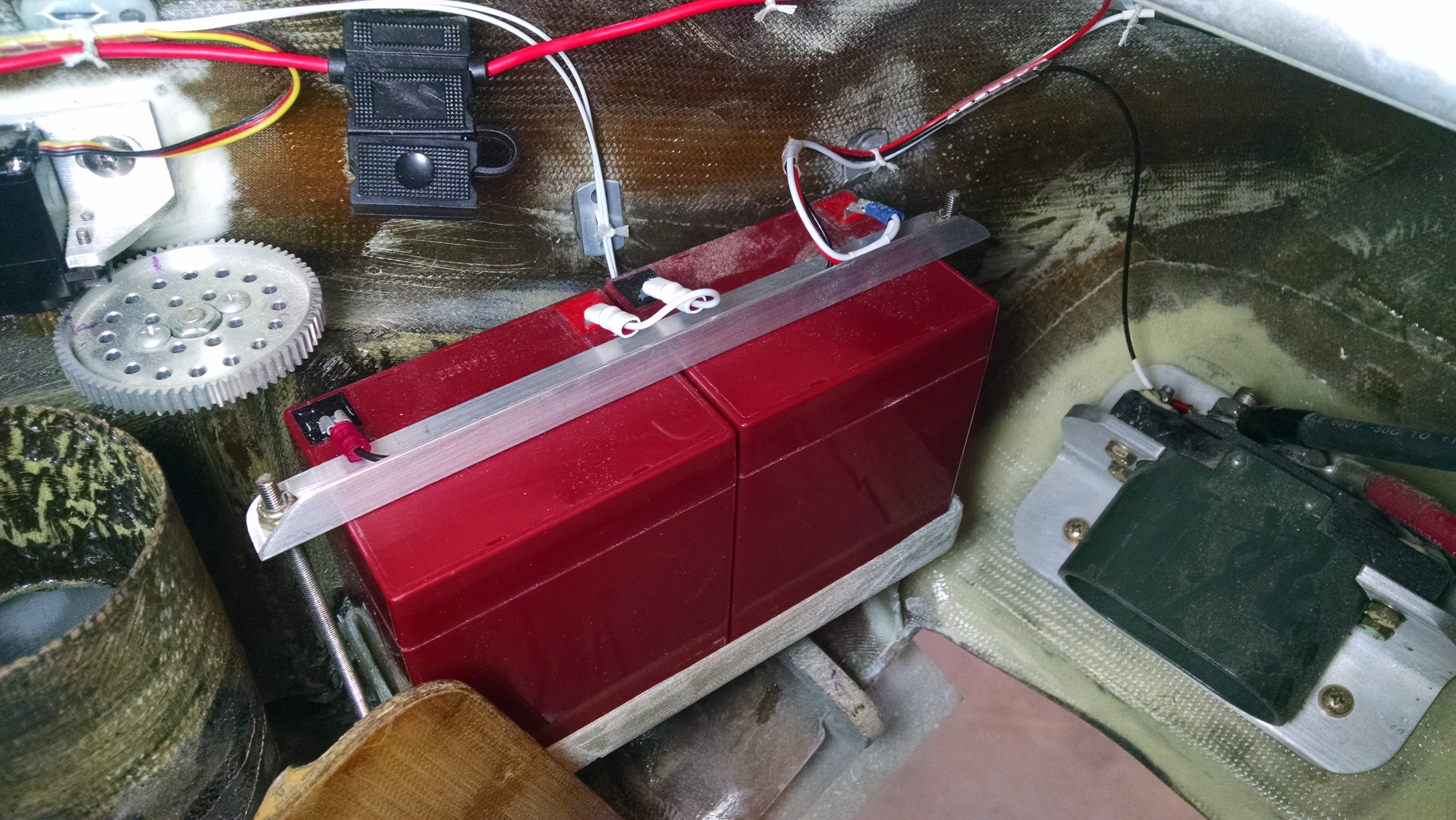
Mounting in the nose was a bit of a challenge.  First I had to find a spot that was as far forward as possible but not interfere with the nose gear or anything else. Then I had to fabricate the supports and hold it in position while in glassed everything in place… And it had to be level.

2015-11-03 IMG_20151103_115537526

Once that was bonded in place, I had to fabricate the hold downs.

2015-11-12 IMG_20151112_104449136

Then I just had to wire everything up.

Battery

The primary power comes on whenever the master switch is on.  I’ll have a second switch on the panel to apply the backup battery power to the secondary input of the EFIS. So I’ll throw the backup battery switch while I’m doing the pre-flight check, Then when I’m ready to start the engine, the EFIS will be up and running.

Engine Dehydrator

This entry is part 45 of 50 in the series 12 - Engine / Propeller

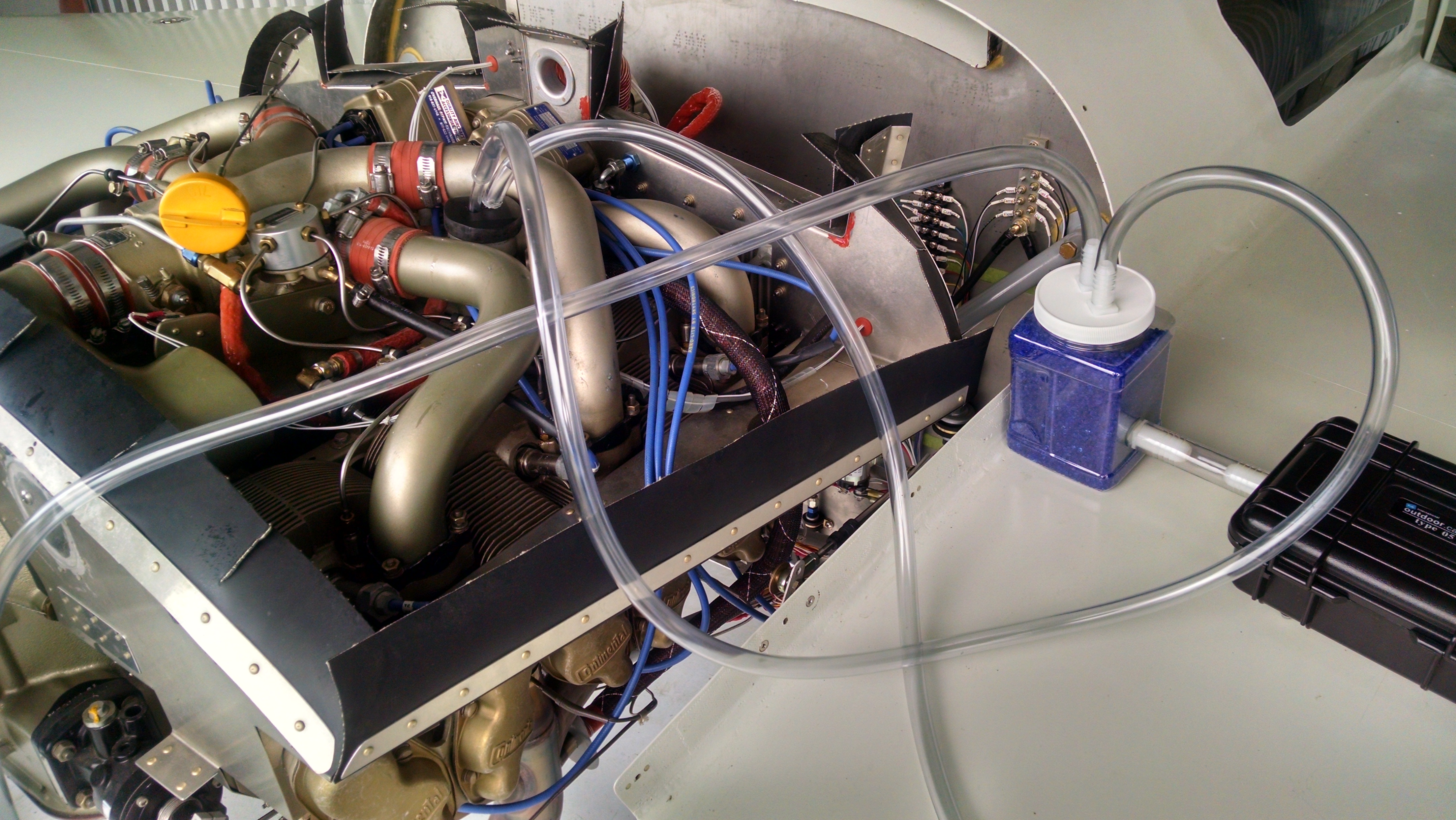
One of the things that is bad for engines is moisture (that’s why all the aircraft boneyards are in the desert). A fellow member of the CPS (Cessna Pilots Society) has built an engine dehydrator. That I’ve been using for a while now.

You connect the tubes to the oil filler port and exhaust pipes. Then when you switch on the box, a small air pump recirculates air into the engine after passing it through a bottle of desiccant. The pump runs until the humidity gets to 5%.  Once the humidity rises to 10%, the pump turns on again so that in air inside the engine is always between 5-10% humidity.

2015-07-04 IMG_20150704_173935480_HDR 2015-07-04 IMG_20150704_173940633_HDR

I’ve seen some of these homebuilt systems that run either continuously or on a preset timer. I like this one because it actively monitors the moisture level.

Not sure if it’ll make any difference but it’s a lot more humid here in FL than it was in IL.

If you’re interested, contact Jerry Olson at jolsonpt38@sbcglobal.net. He will need to know what type of engine and if you made any modifications that he needs to accommodate (like my breather tube into the exhaust).

Fouled injectors

This entry is part 46 of 50 in the series 12 - Engine / Propeller

After the first few flights, I had Malcolm open up the fuel filter and clean it out. I cleaned out the tanks as best I could before and after they were sealed, but you can never get all the debris out. So cleaning out the fuel filter after a few hours is called for.

Malcolm reported the usual amount of crud that he sees in the filter at this stage.

At about the 15 hour mark on my Phase I flight testing, I had a cylinder come up cold during the runup. Now I’ve seen this more times than I count.  It’s always a fouled plug that is usually from idling full rich for too long.  The standard approach is to run up the engine and aggressively lean engine.  And has so many times in the past, it cleared the fouled plug.

But then about two flights later, I had two cylinders come up cold on the run up pad. Now that’s one I haven’t had before. I leaned out the engine at run up power to no avail. After a few more attempts the cylinders were all firing properly again. I made a mental note to make sure and lean the engine for ground operations like I have been with the Cessna.

Two flights later, it happened again. But this time I was only able to clear one of the cylinders. So I checked the mags and discovered that the cylinder was dead for both mags.  When it’s a fouled plug, it’s usually the bottom plug so I should have seen power on the top plug. Which meant that it must be a fouled (clogged) injector. Oh well.  Back to the hanger.

I pulled the cowling and removed the injector for the offending cylinder and sure enough, it was clogged. I could not see light when looking through it. I got a paper towel and blew through the injector but it wouldn’t clear. I tried a few more times and still couldn’t clear it. While I was walking over the service center, I tried a couple times and it finally cleared. But since I didn’t have the paper towel over the end, I wasn’t able to identify what the material was.

I reinstalled the injector and cranked up the engine and all six cylinders were firing away so I made another flight.

The next morning when I started up, I had two more cylinders that were not firing. A mag check showed that it wasn’t the plugs which meant that I had two more fouled injectors.  So I called Malcolm to come out and give me a hand. While I was pulling the five remaining injectors he was removing the fuel filter.

I cleared out the injectors and then I heard Malcolm say “Check this out”. I looked at the fuel filter in his hand and it was about half full of crud. He cleaned it and this is what came out of the filter.

2015-09-24 IMG_20150924_101057284

He said that was two to three times what he found the first time he cleaned the filter. Our guess is that there was a pocket of fiberglass dust that was stuck behind one of the baffles and that after about 10 hours of flying it got flushed out.

When the filter was reinstalled, we disconnected the fuel line at the servo and directed it into a container. Then I ran the fuel pump for a few seconds. We got a small amount of crud. Emptied the container and did it again. Clear fuel this time.

Hooked the fuel line back up and the engine ran fine.

So I’m going to be checking the fuel filter about every 5 hours for the immediate future until it shows clear.


The end of a long journey…

This entry is part 5 of 7 in the series 16 - Flight Testing

Yesterday, I arrived at my home field with the Velocity.  Seven and a half years after making the first fiberglass layup.
Weather was tricky as there were showers and clouds between Sebastian and Orlando that I had stay clear of (there is currently no weatherstripping and the plane is not certified for IFR).  But once past Orlando is was a clear shot to Panama City.

Two highlights were having Tampa approach pointing me out to a passing Delta flight (“Delta 123, you have a Velocity off your right at 6,500”). I couldn’t figure out why a 767 would be so low or why they never called my to tell me about the Delta flight. Then I noticed they were at about 18,000′.  That was cool.

Then I passed a Skylane like it was standing still. That was fun.

Arriving at my home field it was empty.  I figured Ann would be waiting for me so I gave her a little show.  I did a low approach and overflew the runway.  I had to pull the power way back because it was really bumpy.

I had been wondering how visibly the flashing landing lights would show up. She said that she could see me coming for a long way off.

Video of the low approach and landing (apologies for the portrait mode… what are you gonna do?).

I’ve got some other posts that precede this one but I wanted to get this up ASAP.