13.7 Wiring

This entry is part 37 of 67 in the series 13 - Electrical / Instruments

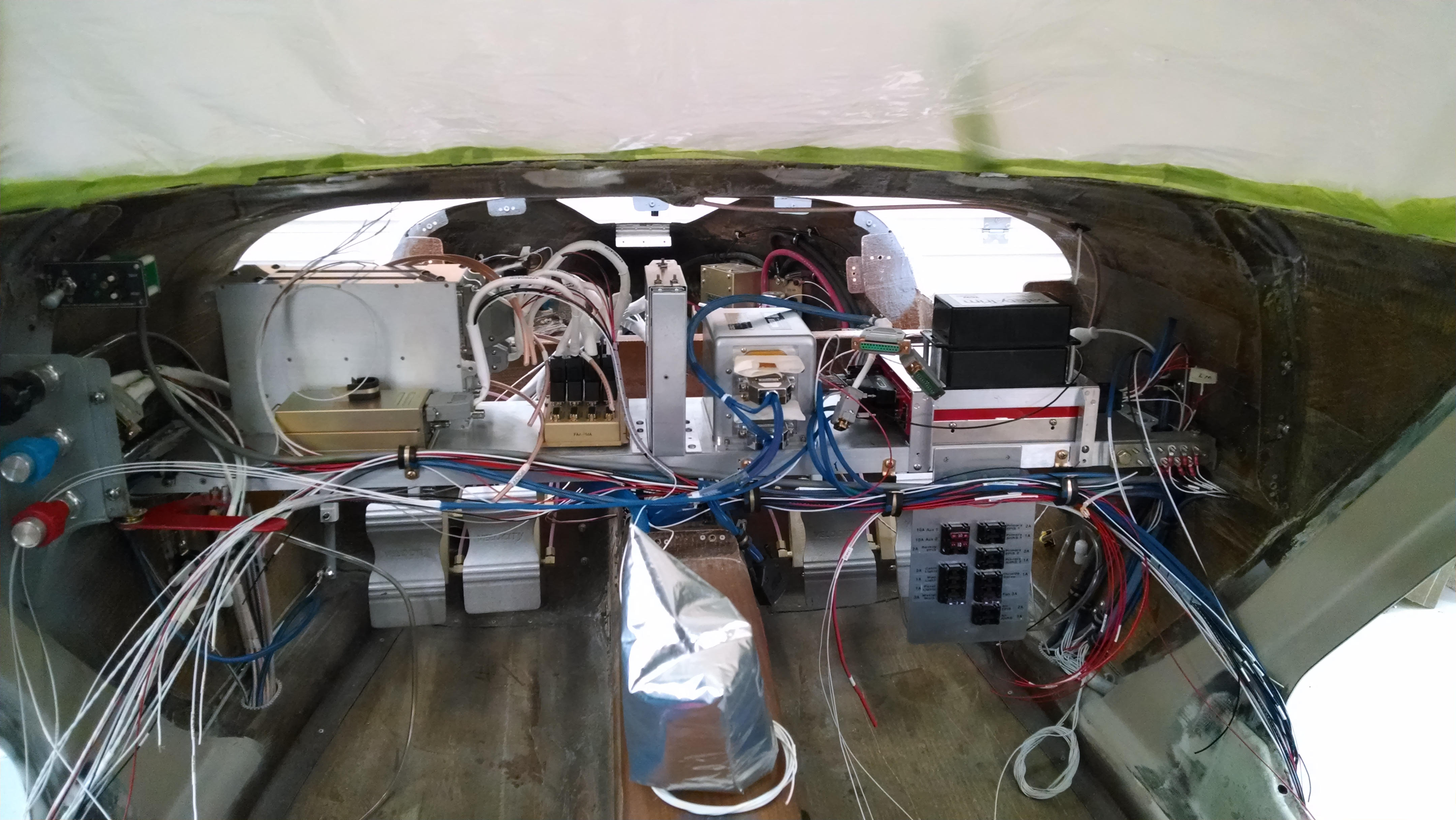
Seems like a step backwards. It’s just a mess.

I’ve terminated some of the connections but trying to keep everything organized is a real challenge.  All the wires are in place, I just need to finish terminating them.

Here I’ve grouped the wires based on their destination.

2014-04-30 IMG_20140430_193823030a

Next I’ll try to bundle them and finish this up.

13.2 Panel painting

This entry is part 38 of 67 in the series 13 - Electrical / Instruments

I’ve thought about different finishes for the panel. A couple of builders have gone with a carbon fiber finish. This looks nice but there are a couple of potential issues:  1) Getting the fabric to lay perfectly straight can be a challenge. 2) The finish would be glossy. I suppose that I could find a satin finish epoxy. 3) There is no chance for repair or modification. If a hole needs filled, it’s going to stick out like a sore thumb. With paint, you can either touch up or repaint the panel.

So then the question is, what color? On older aircraft, flat black was common. Newer panels when with gray in either flat or satin finish. I looked around and found a metallic dark iron gray.

Here’s the result (with the lower switch panels installed.

2014-05-07 IMG_20140507_094543947 (Large)

13.2 Panel installation

This entry is part 39 of 67 in the series 13 - Electrical / Instruments

I finished up the wiring and installed the pitot static lines. Mounting the speed switch for the two-speed trim controller required a building a mounting bracket. The speed sensor adjusts how fast the pitch trim motor runs (faster at slow airspeed and slower at higher airspeeds). But there’s an adjustment on the back (or bottom) of the sensor.

2014-05-21 IMG_20140521_093128515_HDR (Large)

When the panel was installed, I discovered that some of the wiring was interfering with the parking brake linkage and had to reroute a wiring bundle.

Here’s the installed panel with the landing gear control, master warning panel,  lighting sub-panel, left lower-panel, right lower-panel and backup EFIS mounted.

2014-05-30 IMG_20140530_075752347 (Large)

Then I installed the two EFIS displays.

2014-05-31 IMG_20140531_192555425 (Large)

Then I threw the master switch.

2014-05-31 IMG_20140531_193001095 (Large)


12.3.5 Minor setback on Avionics wiring

This entry is part 40 of 67 in the series 13 - Electrical / Instruments

Tim at Approach FastStack saved me a ton of frustration when he discovered that I would have to have two displays. So here’s how the all the avionics will connect to the displays:

HXr-1Serial 1: Nav-1
Serial 2: AHRS-1
Serial 3: AHRS-2
Serial 4: EIS
Serial 5: Audio Panel
Serial 6: Com-1
Serial 7: Transponder
Serial 8: AutoPilot

HXr-2
Serial 1: Unused
Serial 2: AHRS-2
Serial 3: AHRS-1
Serial 4: EIS
Serial 5: GPS
Serial 6: Com 2
Serial 7: VPX
Serial 8: AutoPilot

But once I started getting everything connected, I discovered that the VPX should be connected to the number 1 display. That display will be on prior to engine start and the only way to see if there are any electrical problems is if the display that the VPX is connected to is powered on.

So a quick call to Tim and he said “no problem”. He’ll send me a new configuration plug that will put the VPX on EFIS-1, Serial 7 and the transponder on EFIS-2, Serial 1. Excellent! Two days later, I get the new config plug, and start getting the HXr’s setup. But the transponder isn’t talking to the EFIS-2!

Now here’s the big problem with remote avionics: You don’t even know if it’s on! With panel mount stuff, there are all sorts of lights and such that tell you if it’s on. So when the transponder isn’t talking, there’s no way to know if it’s dead, or on and not talking. I check power and I can see 24v to the connector that connects to the transponder. And the ground is good. So I can assume that the box is getting power. But I still can’t verify that it’s actually on.

What to do?

I connected the old config plug and powered everything up. Transponder is talking away. New config plug and the transponder is quiet.

Hmmmm.

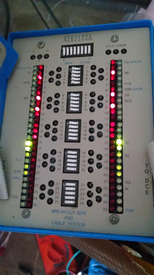
Well, back in my early years, I used to spend a fair amount of time troubleshooting computer peripherals that communicated using RS-232. Which, coincidentally, is how the transponder talking to the EFIS. So I dug around in my old tools and luckily enough, I still my old breakout box. So I connected this in-line between the transponder and the EFIS and here’s what I saw using the old config plug:
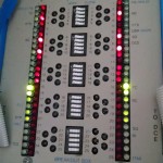
2014-06-13 IMG_20140613_172249713 (Large)

You can’t see it in the picture but the transmit and receive lights are flashing away.

With the new plug, those lights are out.

I do some tracing and it seems to me that the config plug is wrong. I email Tim and within an hour he responds that they made a mistake (and apologizes all over the place). I get a new config plug within a two days and all is well.

I just goes to show: it’s always something.

13.8.2 Annunciator Panel Problem

This entry is part 41 of 67 in the series 13 - Electrical / Instruments

On the annunciator panel, there are eight indicators:

Fuel Pump On
Pitot Heat On
Low Oil Pressure
Low Voltage
Starter Engaged
Pilot Door Unsafe
CoPilot Door Unsafe
Parking Brake Set

Most of these are activated by a wire going to ground which completes the circuit and turns the indicator on.  The Low Oil Pressure indicator wire goes to the Grand Rapids Engine Information System (EIS) alarm.

When I powered up the EIS and annunciator panel I noticed a minor problem.

2014-06-18 IMG_20140618_153216193_HDR (Large)

The indicators don’t photograph too well, but you can see the Low Oil Pressure is lit. Just not very bright. The problem is that I haven’t programmed the EIS to alarm on anything. Which means that the indicator is not on.  This occurs because EIS was designed to illuminate an incandescent light bulb. This results in some power leaking through the circuit that wouldn’t illuminate a incandescent bulb but does cause an LED to come on partially.

The standard fix for this is to put a 1k resistor across the LED to drain off the leaking voltage. But when I did this on the oil pressure LED, in addition to stopping the partially lit LED when it was supposed to be off, it also made it dimmer than the rest when it was supposed to be on.

Now this wouldn’t be a huge problem if it weren’t for being able to adjust the brightness of the annunciator panel. When I turn the brightness down, the Low Oil Pressure LED actually goes out while the other LEDs are still on. This could lead to not seeing a low oil pressure warning.

I tried numerous fixes and none worked. I eventually got a tip to use a MOSFET to control the circuit. This required quite a bit of hacking on the original PCB but it worked.

2014-06-23 IMG_20140623_133758157 (Large)

It ain’t pretty, but it gets the job done. If/when I ever make a version 2 of the PCB, I’ll integrate the MOSFET circuit into the low oil pressure line.

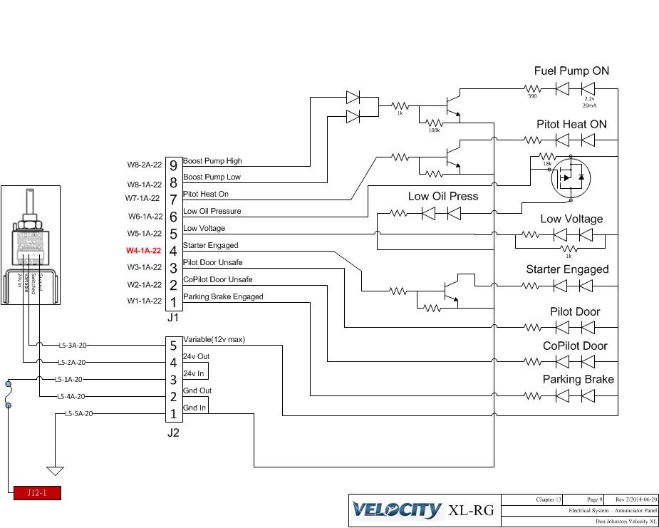
Here’s the current annunciator circuit for anyone interested.

2014-06-20 Annunciator

13.6 Power Supply

This entry is part 43 of 67 in the series 13 - Electrical / Instruments

I went with a 24v electrical system. There are a couple of reasons behind this.

1) All new production aircraft being built today are 24v. 2) A 24v system is more efficient, uses lower current and requires a smaller diameter wire.
3) The engine came with a 24v starter and alternator.

Maybe not the best reasons, but they’re mine and that’s the way it is.

Once I started doing the electrical system, I learned of a drawback to 24v systems; In the experimental aircraft market, many of the suppliers are either 12v only or charge extra for 24v.  So for things like the EFIS screens, I had to pay a little more to get the 24v version.

But the area that really bit me was in batteries. The 12v guys have tons of small, lightwieght batteries to choose from. 24v batteries are pretty much unchanged. Frustrating, but I can live with that. Where it really stings is in battery backups. The EFIS supplier (Grand Rapids Avionics) have a backup battery that will keep the EFIS and AHRS screens alive for at least an hour if there’s an electrical system failure.  But it’s only available in a 12v version. That’s not a huge problem as I’ve got two alternators.

However, the EFIS screens also show engine information. And that’s nice to see when you start the engine. But when you start the engine, the battery voltage can drop low enough (under 20v) that the EFIS reboots.  So how to keep the primary screen glowing while starting the engine?  I looked at getting a couple of small 12v scooter batteries and wiring them in series. But then I would have to find a place for them. Possible, but that would add more work and I’m not looking for new work.

I thought about building a “de-slumpifier” from some plans I got from Eric Jones and Perihelion Design. Basically, it’s  a bunch of capacitors that discharge when the voltage drops to maintain 24v for a short period of time. But remember, I’m not looking for new things to do.

So then I got an email from Tim at TCW Tech. He provided my trim controllers. They also have an Intelligent Power Stabilizer (IPS). This is like the “de-slumpifier” in that it will continue to provide 24v if the input power drops down, but the IPS will continue to put out 24v all continuously as long as the input voltage is above 10v. Now it can only supply about 5amps but since the EFIS only draws about 1amp, that’s fine.

The next problem was where to put it.  My Avionics Sub-Shelf wouldn’t have enough room. So I have to expand it.

Here’s the original sub-shelf which sits over the VPX. The TCW Tech Trim Controller is on top. The empty area behind the trim controller is for the GPS.

2014-05-10 IMG_20140510_100804506 (Large)

And here’s the expanded sub-shelf with a penthouse suite. The IPS is on the lower shelf where the GPS was going to go. Now the GPS will go on the upper shelf.

2014-07-16 IMG_20140716_111956488 (Large)

Then I just added a pair of fuses to the fuse panel for the output to the primary EFIS and AHRS.

13.8.1 EFIS alternate power

This entry is part 52 of 67 in the series 13 - Electrical / Instruments

One of the problems with a 28v electrical systems is that some of the goodies that are available for 14v electrical systems don’t exist for 28v.

One of those “goodies” is a backup battery for the EFIS. During engine start, the battery power will drop. If it goes below around 19v, the EFIS shuts down. Now it takes the EFIS about a minute to power up and it displays engine information. So if it drops offline when I start the engine, I won’t know what’s going on with the engine for about one minute.

Grand Rapids sells a backup battery that will keep the EFIS up if the primary power drops off. But it’s only available for the 14v version.

I thought about getting a small 24v, 5amp battery for this purpose, but then I’ve got a deal with finding a place for it, wiring it into the existing electrical system so it can recharge, etc.

TCW Technologies (who make the trim controller) also have, what they call, an Intelligent Power Stabilizer (IPS). As long as there’s about 12v coming in, it will put out a steady 24v. So I purchased one and tested it out. I was able to drop the input power to about 10v before the output dropped below 24v.

I went it install it on my avionics sub-shelf but I realized that I wouldn’t have anyplace for my GPS.

Here’s version 1 of the sub-shelf.

2013-12-06 IMG_20131206_170639_577 (Large)

So I had to add another level to the shelf.

2014-07-16 IMG_20140716_111956488 (Large)

The IPS unit is on the lower shelf. The GPS will go above the IPS on the top shelf.

13.1.9 ELT Installation

This entry is part 42 of 67 in the series 13 - Electrical / Instruments

While at Oshkosh, I decided to get an ELT. I wanted one with a built-in GPS so I wouldn’t have to run a wire from the primary GPS to the back of the cabin. I stopped at Artex where they had their latest unit, the ELT1000, on display. I asked the rep if this new ELT required a GPS and was told “no”.  As a bonus, if you bought the unit at the show, you also got a handheld ELT with integrated GPS. Cool!

So I bought one from Dewey and Pacific Coast Avionics.

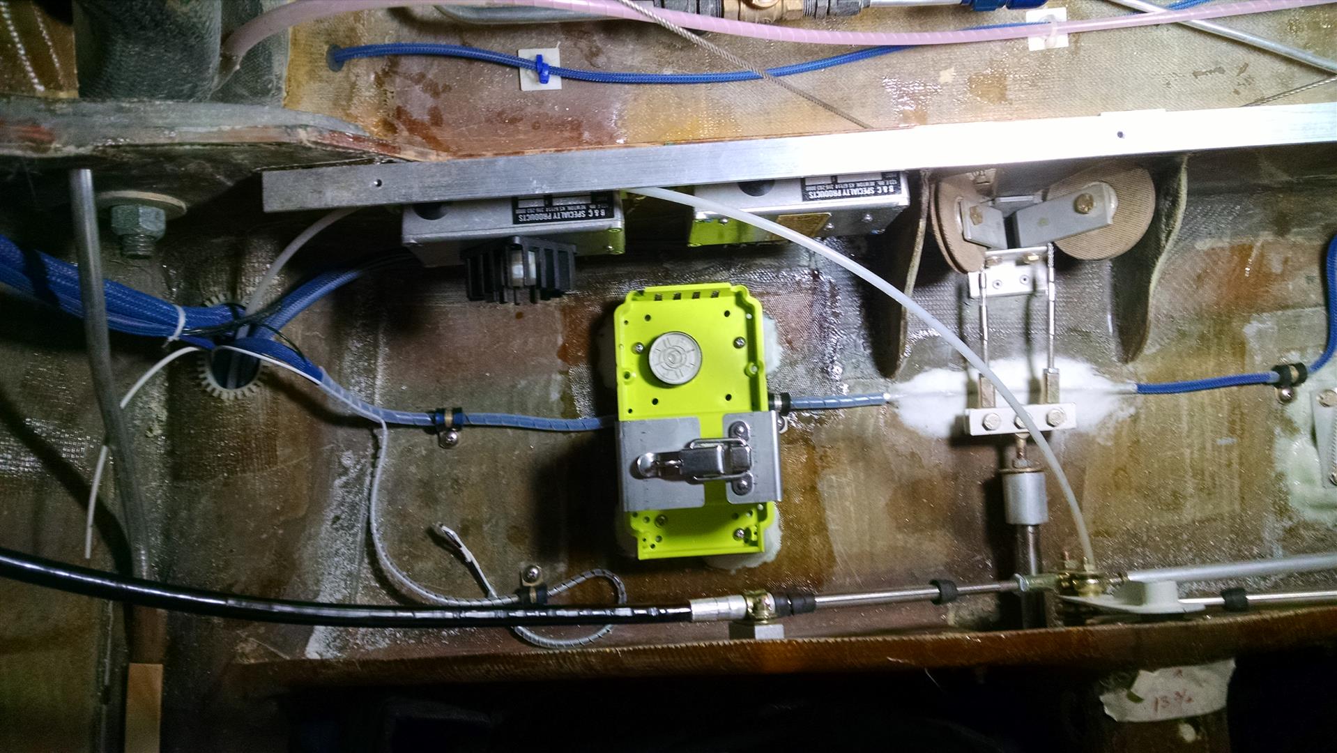
I got back to the shop and decided to mount it between the gear bulkhead and the whaletail. So I used some leftover aluminum stock for hardpoints and glassed them in using the mounting base to keep them in position and the ELT level.  2014-08-01 IMG_20140801_080951435 (Large)

Then I glassed over the hardpoints with 2xBID.

2014-08-01 IMG_20140801_080749709 (Large)

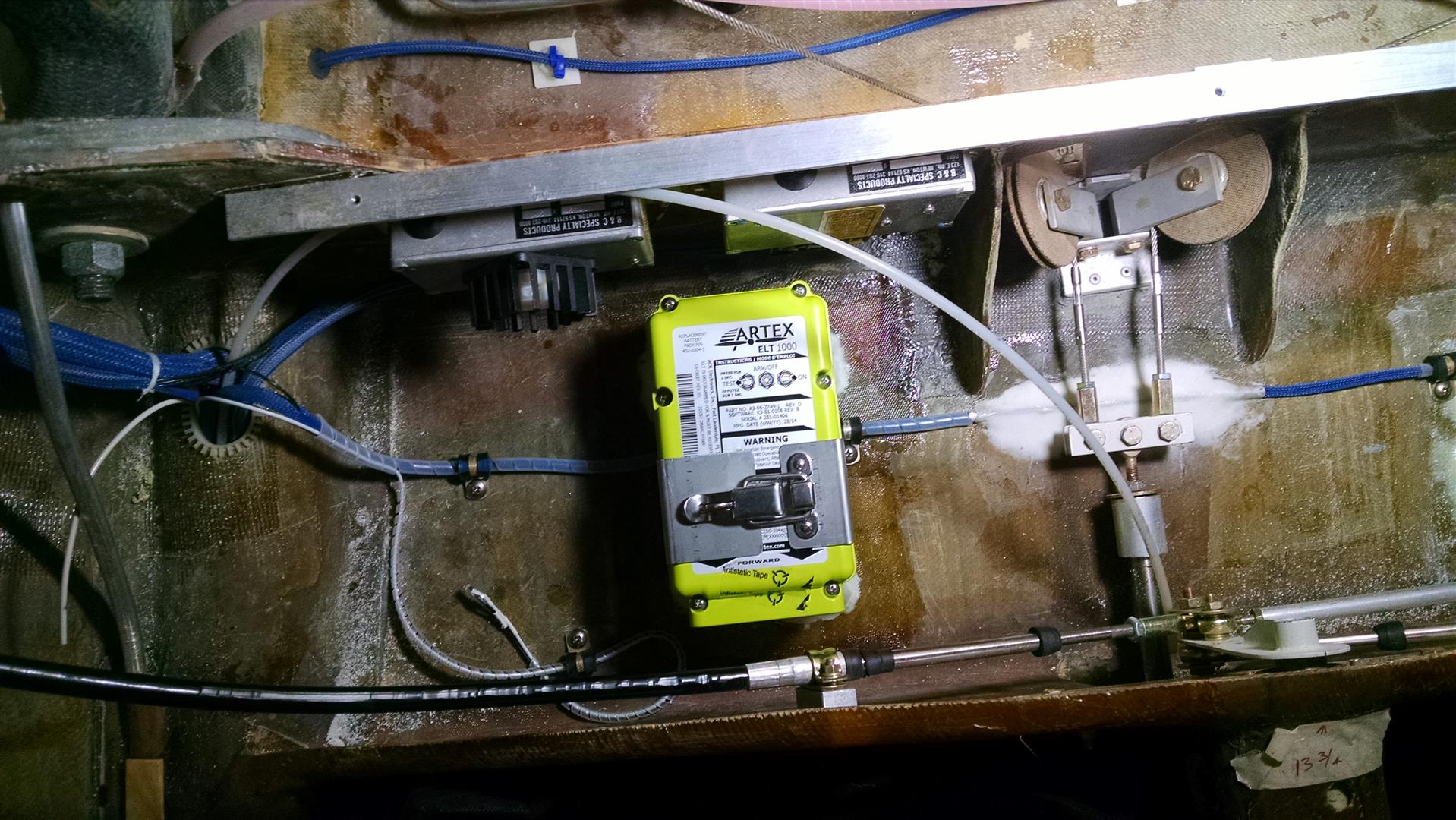
And here’s the ELT secured in place.

2014-08-11 IMG_20140801_081114820 (Large)

Then it was time to pull the cables to the control head. That’s when I discovered the problem.  There were two wires that were identified as “GPS signal”!?!?  And I couldn’t find an antenna connection for the GPS antenna.

So I called Artex.  The first person I spoke to said that the unit definitely comes with an internal GPS. When I asked about the GPS antenna, they said “let me ask someone about that”. I got transferred a couple more times and finally got the head of sales. He told me the unit does not have an internal GPS and that there was no way any of his people would have said that. Yeah… right.

But he did step up and say that if I wanted to return it for a full refund that I he would contact Dewey to make sure I was taken care of.

So contacted Dewey to see what other options were available. After a evaluating the options, I decided to keep the ELT and run a couple wires up to the panel. It would cost more for an ELT with a GPS and I already had the mount installed anyway.

So I pulled a extra wires and mounted the remote control head in the panel.

IMG_20140826_104320680 (Large)_20140826_094334 (Large)

For the antenna, I considered an foil dipole on the floor or ceiling but if there were a crack in those locations, it would diminish the signal. So I decided to use the provided whip antenna. For the location, I went with the right side between the gear bulkhead and the whaletail. Mounted vertically, it would be hidden by the box for the vanity panel.  I made a ground plane that had a radius of 7.29″ (406MHz wavelength of 29.17″ / 4 = 7.29″) and mounted the whole thing under the baggage shelf.

IMG_20140813_085241198 (Large)

When the side boxes are on, it’s out of sight.

2014-06-18 IMG_20140618_131438203 (Large)


13.7.4 It’s always something…

This entry is part 44 of 67 in the series 13 - Electrical / Instruments

gilda112912


Just when you think everything is going okay…

Last year when I was laying out where all the avionics was going, I made up foam blocks that were the size of all the different boxes.  Then tried them in different locations to make sure that I would have the correct clearance with the displays, elevator push tube, and everything else.  I came up with the layout pictured here:

2014-04-19 IMG_20140419_110502292a


This is the view from inside the cabin looking forward.  That vertical box in the center is the PS Engineering PAC15EX audio panel. It comes with mounting hardware that allows it to be mounted horizontally or vertically.

After I had gotten everything installed, I was still waiting for the GPS from Grand Rapids.  But it was beginning to look like vaporware.  Whenever I called, I would hear that it’s going to be available “soon”.  Which is what I had been hearing for almost two years since I first learned of the GPS. So I figured that I needed a “Plan B” in case the GPS never materialized.

I decided on a Garmin GNS400W.  There are tons of them in service (which means that I should be able to find one used fairly cheap) and I’m very familiar with the user interface. The problem is that there was only one spot in the panel (upper center) that it had a chance of fitting, but even there, the audio panel would be in the way.

So I had to relocate the audio panel.

2014-08-26 IMG_20140826_170407171 (Large)

This is the view from the front of the plane. You can see that I’ve re-oriented the audio panel 90 degrees and mounted it just forward of the Com and Nav radios.

Fast forward about two months and I get a box from GRT with my shiny new IFR GPS!  So I moved the audio panel for nothing.  But that’s okay.  No reason why it can’t stay in it’s new location, right?

Wrong.

One of the first things that I did once I got down to Sebastian was mount the wings and canard. Once the canard was on, I realized that I hadn’t considered correctly estimated the pitch trim spring area of movement.  The upper cable of the audio panel is now  interfering with the travel of the spring.  Which means that I’m going to have to move the audio panel back to it’s original position.

Except (at the time) I couldn’t remember why I moved in the first place!  This resulted in many a night trying to remember why I moved that audio panel.  Otherwise I might move it back and realize that there was a good reason I moved it in the first place.

Eventually I searched though my emails and found one to Malcolm (with that picture) telling him that I had moved the audio panel to accommodate a possible install of a GNS400W.

So on the next trip down, I’ll move the audio panel back to the center of the avionics shelf.


13.0 Wire routing

This entry is part 45 of 67 in the series 13 - Electrical / Instruments

One of the tasks with the electrical system is securing the wires. Larger wires like the main power distribution wires and large wire bundles are secured by Adel clamps.  2013-12-13 IMG_20131213_101703_841a

It’s also possible to use Adel clamps for smaller wire bundles. This is the autopilot roll servo wire harness.

2014-08-01 IMG_20140801_080749709 (Large)

But in some places, Adel clamps are difficult to use if there’s limited space/access since they have to be screwed in and they’re a bit overkill for small wire runs.

One of the places they won’t work is on the gear legs.  I don’t want to do anything that could affect the integrity of the gear leg like drilling a hole in it.

So I picked up a bag of plastic wire tie mounts with self adhesive foam backing at Oshkosh.

$_12

Because the gear leg is not smooth, I made some “pads” with epoxy/cabo covered by some small 1″x1″ pieces of wood covered with duct tape.  Once the epoxy cured, I popped off the wood and had a perfectly flat surface to attach the foam mount to.

Here’s the gear leg with the wire mount.

2013-11-08 IMG_20131108_175421_131 (Large)

It held pretty good… for a while.  Then it came loose.  The amount of pull on the wires when the gear retracts is just more than the foam adhesive can handle. I even found some other places that didn’t have much stress on them which came loose as well.  And since it’s made out of nylon, finding a glue that can adhere to it would be a pain. There are probably some of these available that have NASA quality adhesive but they’re also probably $5 each.

So fellow builder Erik Franks mentioned these guys.

2015-01-10 IMG_20150110_085310377 (Large)2015-01-10 IMG_20150110_085317435 (Large)

Since they’re made out of aluminum, Resin Research epoxy will bond to them very well (RR epoxy is real good for bonding to aluminum!).  They’re small, light and have a lower profile than the plastic mounts.

So next week when I’m down in Sebastian, I’ll swap out the old plastic POS mounts with the new ones.