13.0 Wire Routing (Remediation)

This entry is part 48 of 67 in the series 13 - Electrical / Instruments

I finished the re-securing of the smaller wire bundles.

Here’s the left main gear leg with the wire bundle for the landing gear position sensors.

2015-01-14 IMG_20150114_153735081 (Large)2015-01-14 IMG_20150114_153728438 (Large)2015-01-14 IMG_20150114_153744946 (Large)

You’ll notice quite a few of those crappy, nylon wire mounts were loose. Not only could that damage a wire which would indicate an unsafe landing gear but it could also affect the mechanism itself and prevent the landing gear from locking in place.

So I removed all of those pads and replaced them with the new style. Which are not epoxied in place with structural adhesive.

2015-01-15 IMG_20150115_083238478 (Large)

These puppies aren’t going anywhere!

13.1.8 GPS Antenna Shelf

This entry is part 46 of 67 in the series 13 - Electrical / Instruments

Now that I (finally) have an IFR capable GPS, I need an antenna.  I could have purchased one from Grand Rapids for $550, but I decided to check with the manufacture of the antenna they sell.  Sensor Systems sold me the same antenna for about $425.  Sweet!

Usually the antenna is mounted top of the fuselage.  On aluminum aircraft, you have to put it outside otherwise the metal blocks the signal.  That’s not an issue with a composite aircraft.

Most Velocity builders put the antenna on the canard under the cover known as the “doghouse”.  Other builders create a shelf under the doghouse.

Me and Malcolm went back and forth on the best approach.  Under the doghouse and you have lift up the doghouse and reach in to disconnect the antenna before removing the doghouse completely. On the canard and it’s one more thing competing for space in a very busy area with things that move (trim motor and autopilot pitch servo). And it’s got to be elevated to allow for the antenna cable.

In the end I decided to put it under the doghouse.

So Malcolm did what Malcolm does best: Create things out of resin and fiberglass.

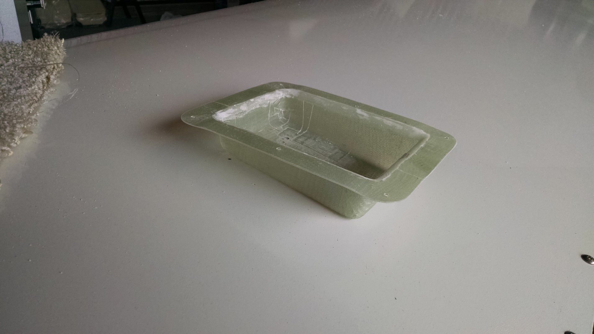
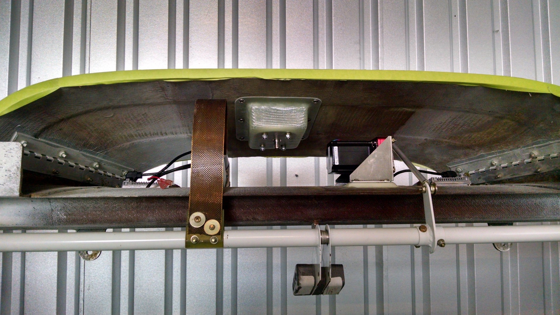
Here’s the GPS Antenna Shelf.

2015-01-16 IMG_20150116_092301942 (Large)

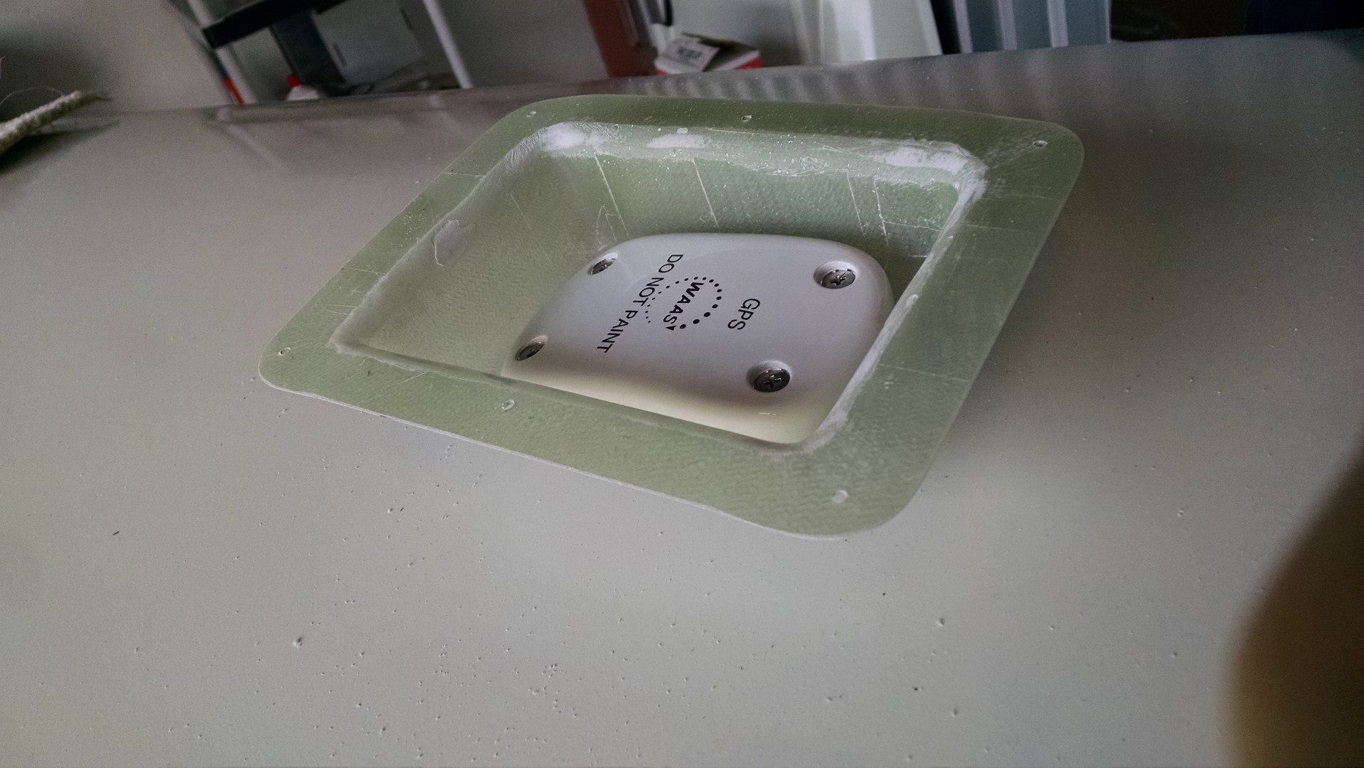
With the antenna installed

2015-01-16 IMG_20150116_092854521 (Large)2015-01-16 IMG_20150116_092832475 (Large)

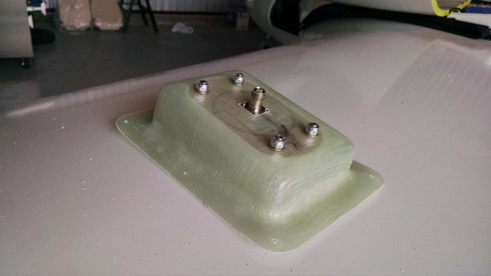
Attached to the underside of the doghouse.

2015-01-16 IMG_20150116_093808645 (Large)

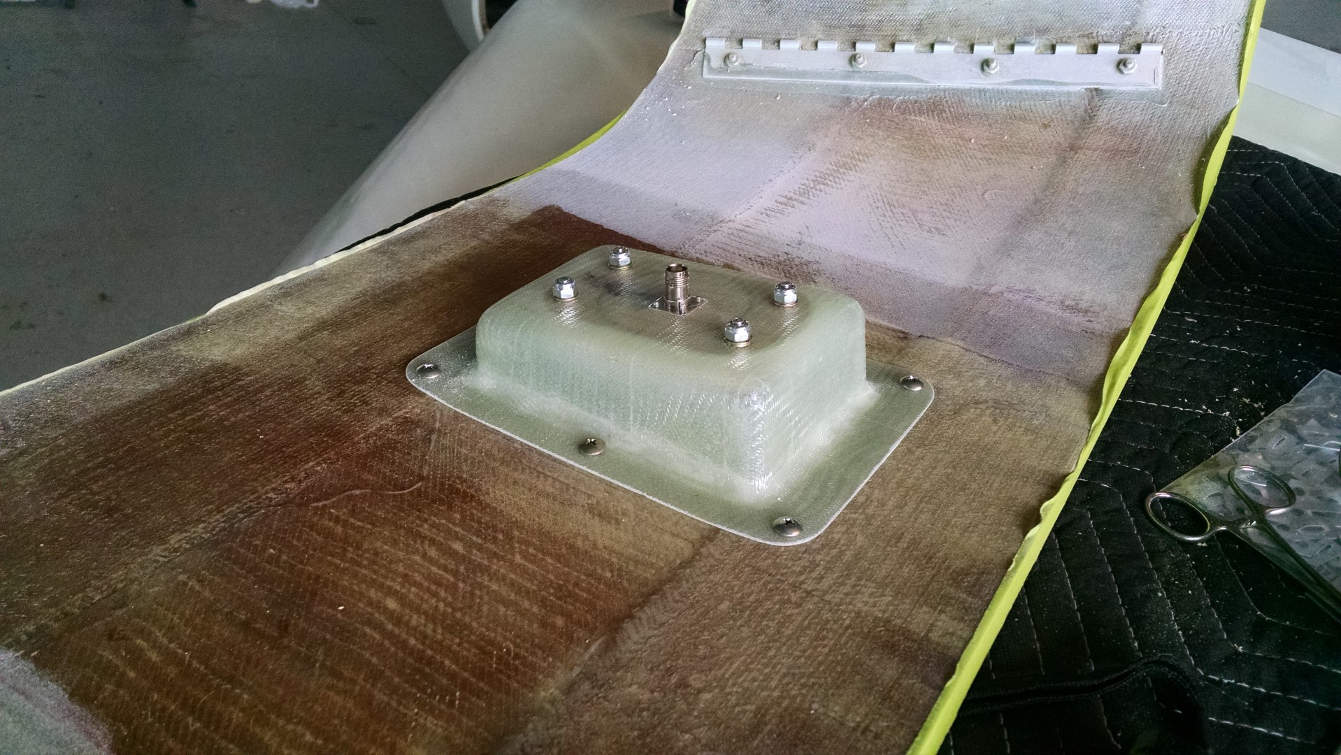
With the doghouse installed on the canard.

2015-01-16 IMG_20150116_093910110_HDR (Large)

13.7.4 Audio Panel Relocation

This entry is part 47 of 67 in the series 13 - Electrical / Instruments

I got the old mounting bracket and relocated the audio panel.

Before:

2014-08-26 IMG_20140826_170407171 (Large)

After:

2015-01-17 IMG_20150117_103302083_HDR (Large)

I got the battery yesterday but had to make a change in the instrument panel today so I won’t get all the electrical hooked up and test to verify clearance from the pitch trim spring until (hopefully) tomorrow.


13.6.1 Battery Hold-Down

This entry is part 49 of 67 in the series 13 - Electrical / Instruments

The battery that I have been using is a used one which came out of another airplane.  The dimensions are pretty standard so I used it as a template when I was building the battery tray.

It was a standard flooded cell, lead/acid battery.  And the cover plate was also the hold down strap.

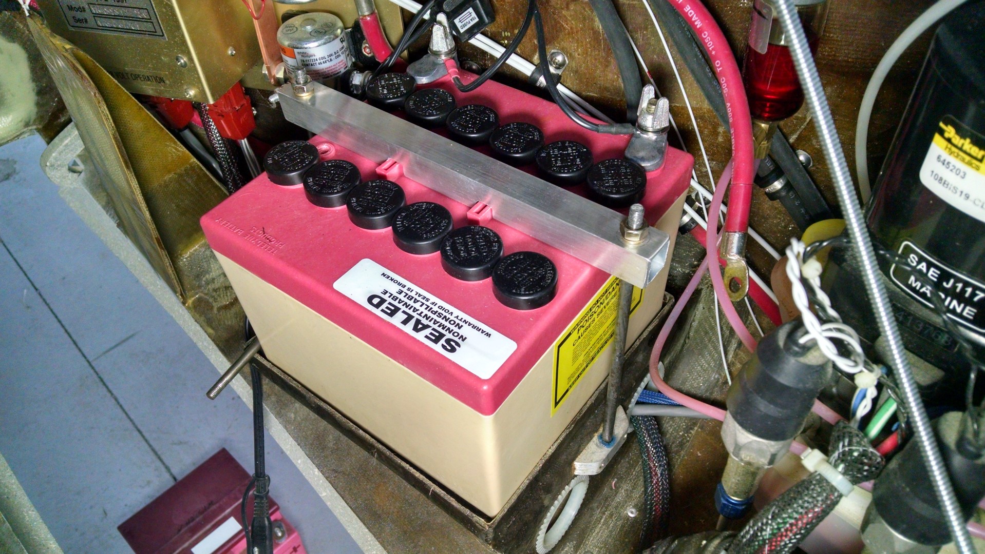
But I decided on a sealed battery.  Which means that I don’t have to worry about putting in an overflow drain.  But the new battery doesn’t have an intergated hold-down.  So it’s fabrication time again.

The battery has these two little… tabs sticking up.  I could have just gone over top of those but I was worried that pressing down on those would cause trouble in the future. So instead of using flat plate, I used I picked up some 3/4″ square stock and cut it to length and notched the square stock. Then drilled two holes for the rods.

2015-01-18 IMG_20150118_092653974 (Large)

Here’s the hold-down bar on the new battery.

2015-01-18 IMG_20150118_093345829_HDR (Large)


13.2.1 Instrument Panel – Final Install

This entry is part 50 of 67 in the series 13 - Electrical / Instruments

With the new battery installed, Audio Panel moved, and GPS installed, it’s time to reassemble the instrument panel for (I hope) the last time.  During this install, I’ll be using locking hardware and securing wires.

Once everything was back together it was time to fire up the electronics for the first time in quite a while.

I was so very happy that everything powered up properly!

2015-01-18 IMG_20150118_154232895_HDR (Large)

Since the glareshield is now installed, I can test the panel lights as well.

2015-01-18 IMG_20150118_154244987_HDR (Large)

And since the wings were now on and wired, I was able to test the Nav and strobe lights.

2015-01-19 1059 IMG_20150119_105945849 (Large)

Next, I’ll install the canard and connect the landing lights, trim motor and heater fan and test those.  I’ve also got to find a headset and see if the radios work.


13.3.3 / 13.5.3 Trim & Landing Light Test

This entry is part 51 of 67 in the series 13 - Electrical / Instruments

The canard is now installed and all the wires have been run.

2015-01-21 1201 IMG_20150121_120138393 (Large)

The TCW Trim Controller works like a champ.  When I first tested it, I thought there was a problem since it would only run for about three seconds and then stop.  But then I remembered that there is a “trim runaway” protection feature which prevents a stuck switch from resulting in the trim being run all the way.  So you just have to re-activate the switch if you ever need more trim.  There’s also a reverse trim function that also works perfectly.

There is also a high and low speed trim function so that when you’re flying slow (like in the pattern) the trim motor runs at a higher speed than it does when you’re flying fast.  I haven’t tested that function yet.

I also powered up the landing lights.

2015-01-19 1059 IMG_20150119_105915478 (Large)

13.99 Instrument Panel overlays

This entry is part 56 of 67 in the series 13 - Electrical / Instruments

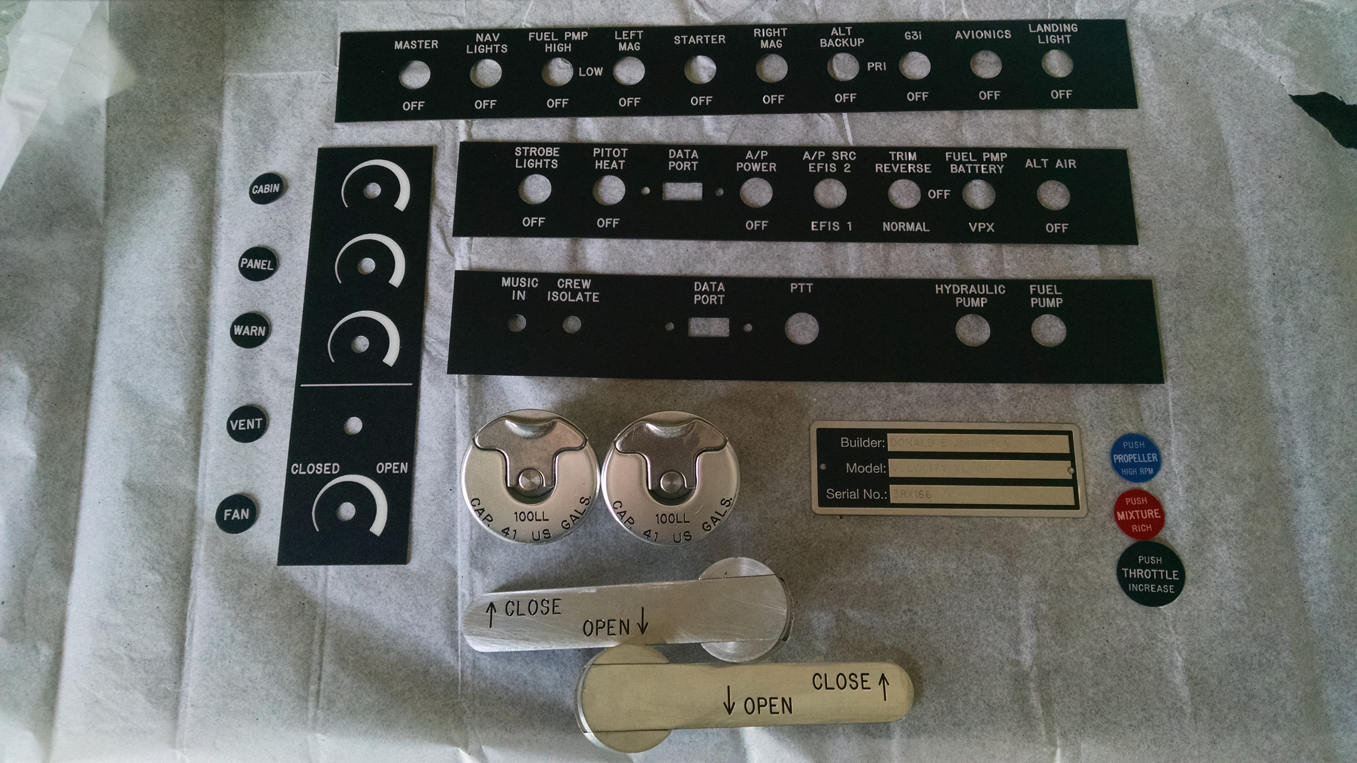
I received an early birthday present today.

2015-04-08 IMG_20150408_105606701

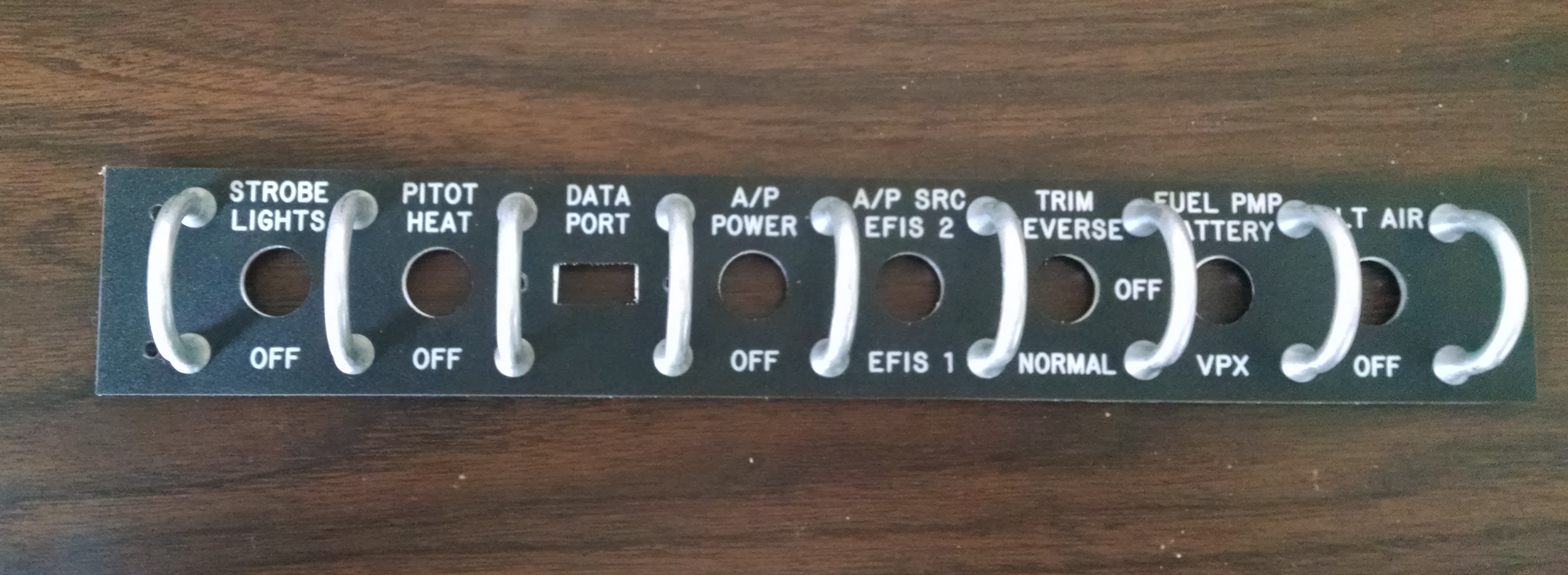
I ordered this through Aircraft Engravers.

So no stickers on the around the fuel caps or on the door.

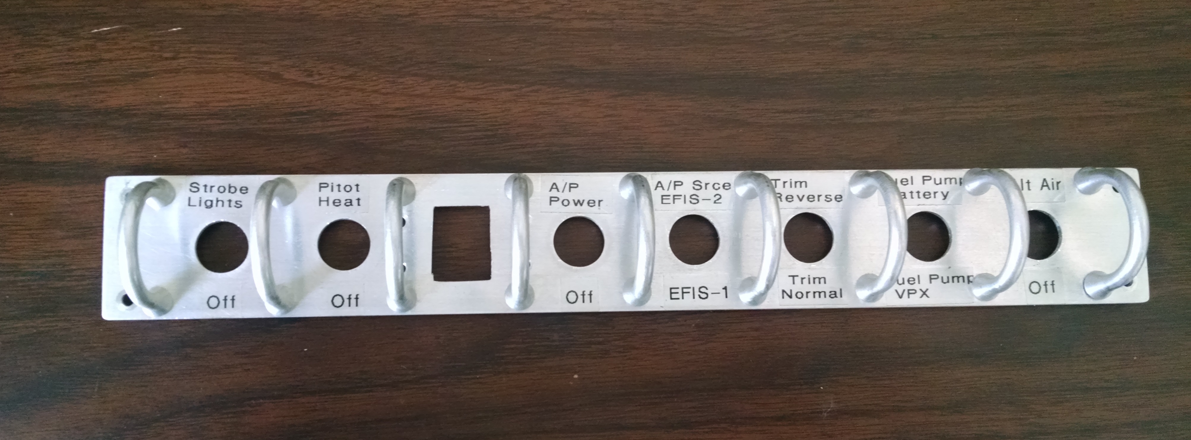
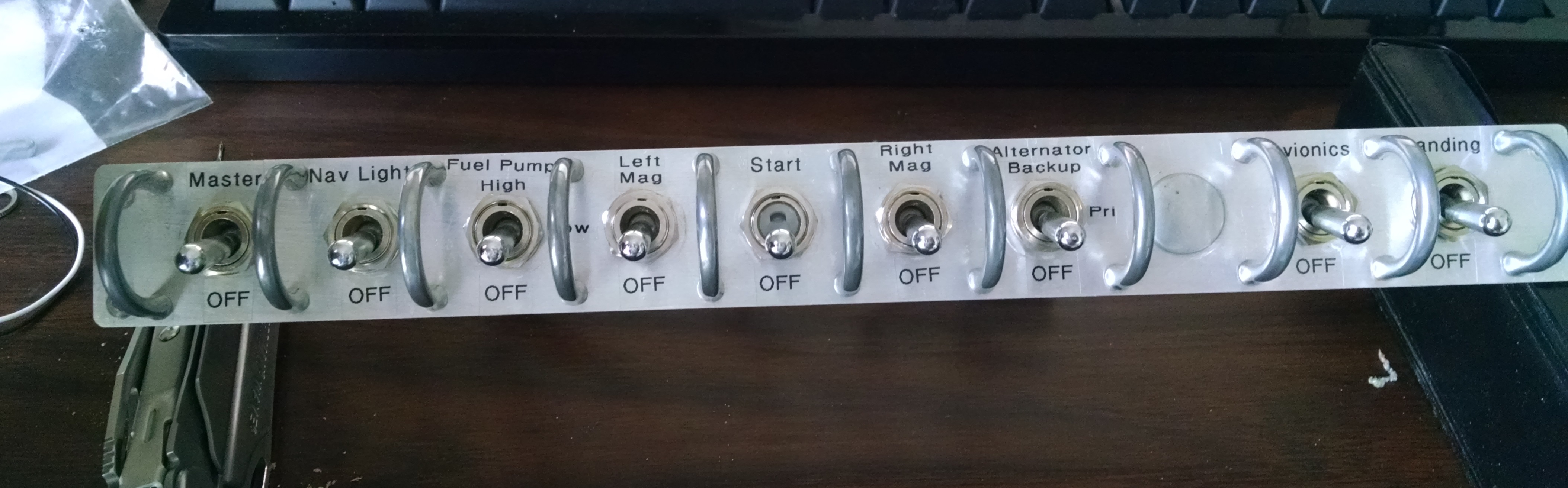
I brought the switch panels home so I could work on the drilling out the mounting and switch guard holes.

Lower Left Switch Panel before and after.

2015-04-08 IMG_20150408_130740804 2015-04-08 IMG_20150408_144929647

Overhead Switch Panel before and after.

2015-04-08 IMG_20150408_1531498192015-04-08 IMG_20150408_185918207

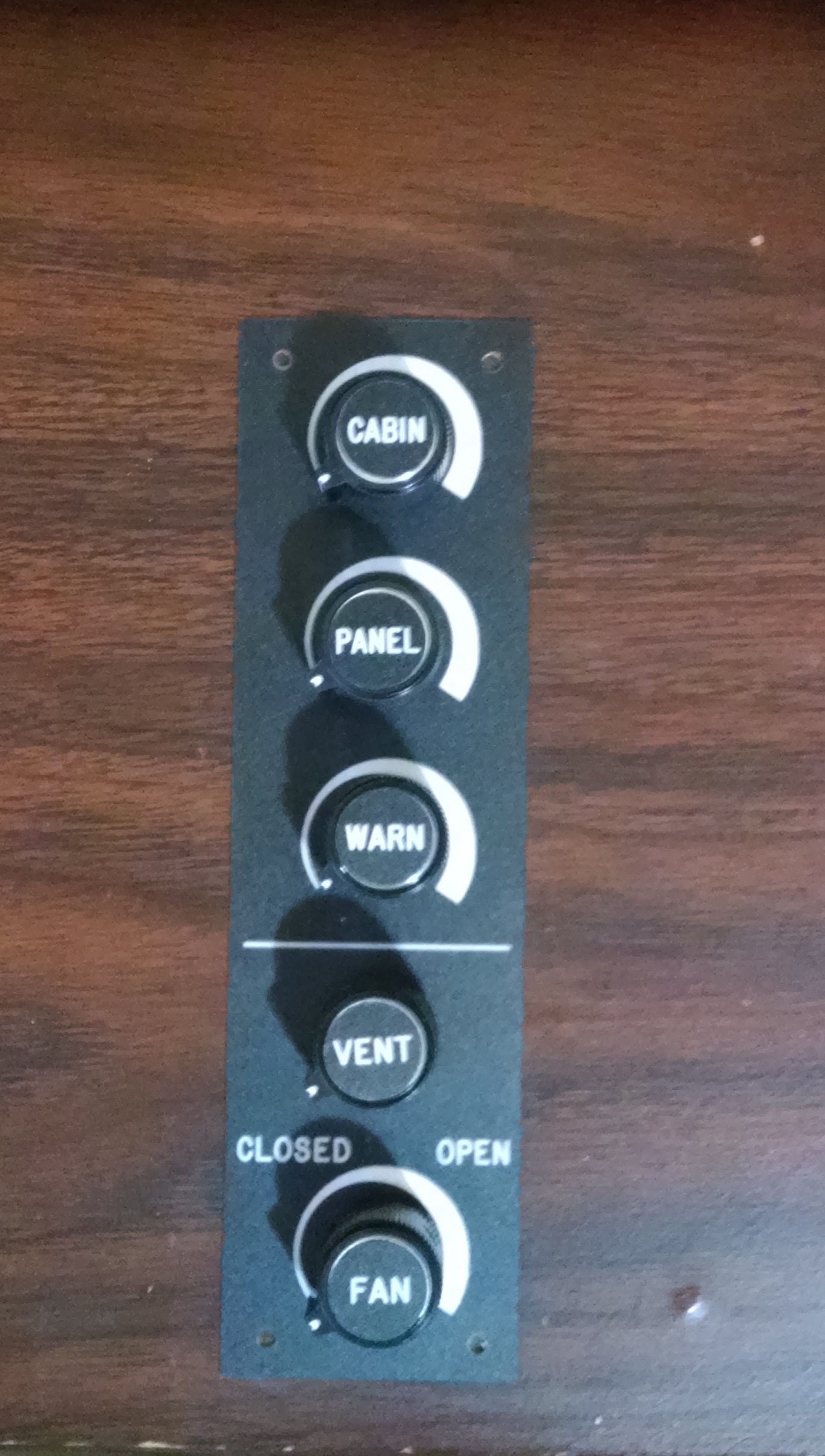
Light Dimmer and Vent Panel.

2015-04-08 IMG_20150408_190513561

13.99 Installing Engraved parts

This entry is part 57 of 67 in the series 13 - Electrical / Instruments

Once I received the engraved parts, it was time to install them.

The fuel caps were easy.

2015-04-16 IMG_20150416_065056544

The door handles were a bit more more. But just as satisfying.

2015-04-16 IMG_20150416_065036011

The engine controls were also easy to install.

2015-04-16 IMG_20150416_084355857

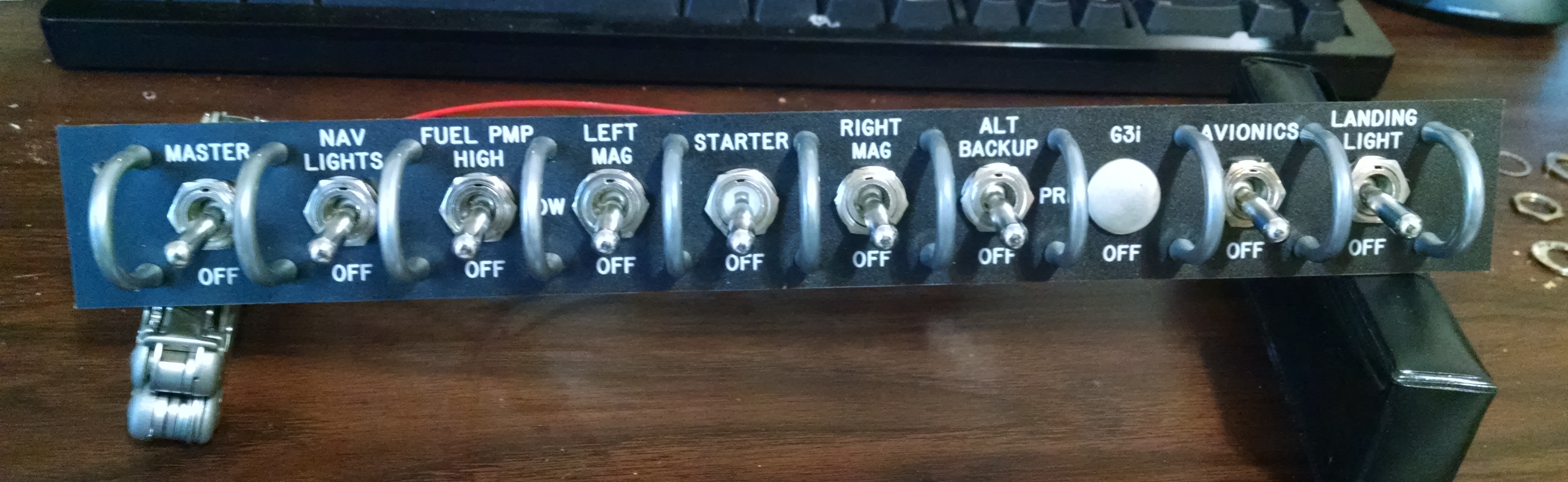
The switch panel overlays were a bit of work since they are actually under the switch hardware. But the result is exactly what I was looking for.

2015-04-16 IMG_20150416_084402820  2015-04-16 IMG_20150416_0844374892015-04-16 IMG_20150416_084415426

13.4 Pitot/Static Remediation

This entry is part 59 of 67 in the series 13 - Electrical / Instruments

Prior to having the airworthiness inspection done, I was planning on getting the pitot/static/transponder check done. Friend and fellow builder Bob (who’s V-twin had a first flight 2 days after mine!) suggested checking the system for leaks prior to the check.

When I checked, it leaked like a sieve.  Couldn’t hold the altitude and airspeed for less than a second.  I pulled the panel (no small feat) and tightened all the fittings and still leaked. I isolated parts of the system and still had leaks. Spent a whole day trying to fix this and had to cancel the test, reassemble everything for the inspection, and come up with a plan B (actually, Plan A since the current system is a Plan B).

This brings us to our lesson for the day.  When learning to fly, you’re told that when a loss of power occurs, that you select a suitable landing spot (within gliding range) and stick with it!  Too often, as people descend, they see another spot that looks much better.  But when they try to make that spot, they run out of altitude. Now obviously, there are exceptions. But the idea of “Make a plan and stick to it” has merit.

This also applies to building. With the pitot/static plumbing, I researched all the different choices for tubing and fittings. What I decided on was “quick connect” system sold by SteinAir. I came across these when I was looking for a alternate static valve that had a toggle switch control.  The parts weren’t the cheapest (at least I thought), but it looked like a good choice.

Then someone told me that you can get “the exact” same type of fittings from Home Depot.  Early on, I made the decision not to use non-aviation parts unless I was absolutely certain that it either didn’t impact safety or that I could determine that the part was as good or better than the traditional aviation grade part. I could not make that determination with the Home Depot grade parts so that idea was dismissed.

Then I heard “Why are you going to use those fancy, expensive parts? Cessna, Piper, Beech have been using plain old NyloSeal parts for years and they work just fine.”  Well, I didn’t have a good answer for that. So I ordered a bunch of NyloSeal fittings and tubing from Aircraft Spruce. I mean, if it’s been working for everyone else, right?

Before ordering, I drew up a diagram:

Pitot-Static Diagram

Once all the parts were in, I hooked everything up and secured the fittings and tubing where necessary.

Here’s a picture after I installed the tubing and put the panel in place.  The arrows are pointing a various tubes and fittings.

2015-07-06 IMG_20140528_084725635

Not the prettiest installation, but it’s behind the panel and with all those fittings, there’s only so much you can do.

Once I discovered that the system was leaking and I couldn’t get it to not leak, I decided to go back to my original plan.

So I made up a new diagram. In the process, I decided to eliminate the “test points” in the system. I had asked the shop that’s been doing the pitot/static checks on the Cessna about what they like to see in a pitot/static system and he told me “test points so I don’t have to tap into a line.”  But it occurred to me that a single test point adds three connections to the system.  After I redesigned the system, for the new hardware, between eliminating the test points and having a 5-port manifolds, I reduced the number of connections from 44 to 28.

Old Pitot-StaticNew Pitot-Static

I also used the “banjo” elbows for attaching to the static ports on the sides of the fuselage. These fittings are very low profile which means that the interior trim will fit closer to the fuselage. Here’s a picture of a standard elbow (left) and the “banjo” elbow (right).  Oh yeah, another huge benefit is that both elbows are full 360 degree swivel.  Which means you don’t have to worry about “clocking” the fittings to get them pointed in the right direction.

2015-06-25 _20150625_143049(1)

The end result is a much neater installation that had no leaks. I also used red tubing for the pitot side and clear tubing for the static side to make it easier to identify the two different lines.

2015-07-06 IMG_20150706_081241770_HDR 2015-07-06 IMG_20150706_081249678_HDR

This is what I removed.

2015-07-07 IMG_20150707_120757151

Static Port Conundrum

This entry is part 60 of 67 in the series 13 - Electrical / Instruments

The static port serves two primary functions: 1) It provides the ambient air pressure which the altimeter uses to determine the altitude. 2) It provides a reference pressure for the pitot tube to determine the airspeed.

The static port called out in the manual is built entirely by the builder.  I elected to purchase a pair of static ports from Aircraft Spruce similar to the static ports on my Cessna 182-RG.  The reason for having two is to correct the static pressure when the airplane is in a slip or skid. If the airplane is in a slip or skid and you have only one static port, then it could be in either a high pressure area or a low pressure area.

When I flew my plane (solo) for the first time, I was elated at the indicated and true airspeed. Indicated (IAS) is what the airspeed indicator shows and true airspeed (TAS) is your actual speed through the air.  To determine true airspeed, you take the indicated airspeed and compensate for temperature and altitude. The bottom line is that I was hauling ass!

But then I noticed my groundspeed. Normally when you’re flying, there’s either a headwind or a tailwind. If your true airspeed is 190 knots and there’s a 10 knot headwind, then you’ll only be traveling 180 knots over the ground.  But when I looked at my groundspeed while traveling south, it was showing about 20 knots slower than my TAS. Okay, I’ve seen 20 knot headwinds more times than I can count. After I turned around, my groundspeed was still about 20 knots slower than my TAS.

Now that’s peculiar.

The next couple of flights, I did a tests of the airspeed. This is accomplished by flying at least three different headings (usually greater than 90 degrees), noting the groundspeed on each heading and by using a formula you can determine your actual TAS along with the current wind speed and direction. What I discovered is that at cruise speed, the airspeed was reading about 25 knots faster than I was actually traveling.

But the slower I got, the closer the TAS got to the actual airspeed.

Now if it were reading slower than actual, that would point to a leak in the pitot system. But faster?!?!

After a lot of thought, I came to the conclusion that the static port must be drawing a vacuum. Since airspeed indication is a result of the pressure of the air being forced into the pitot tube compared against the static air pressure, it seemed likely that if the static pressure were less, the airspeed would read high.

I talked this over with Scott and Rick at the builders center. Scott said that he’s had to put “trip strips” in front of the static port to disrupt the air because it was pressurizing the port but he’s never had a static port effectively de-pressurizing before. He suggested putting a small piece of stir stick behind the port. This should stop the vacuum by pressurizing the port. Once it’s determined that was the problem, then the thickness could be adjusted.

So I taped over one of the ports (easier to test with one port), hot-glued a short length of stir-stick behind the static port and went for a flight.

Now the airspeed is reading about 15 knots low at cruise. This would seem to prove the concept.

But… if the static port were drawing a vacuum, then altitude would be showing higher than actual altitude (less pressure the higher you fly). And if the static port were being pressurized, then the altimeter would be indicating lower than actual.

This caused the hair to stand up on the back of my neck.  Because if I’m flying along at what I think is 6,500′ (westbound VFR altitude) and the static port is being pressurized, then I could actually be flying at 7,000′ (eastbound IFR altitude). But air traffic control would keep me from bumping into someone else, right?  Nope.  ATC thinks I’m at the altitude that my transponder is sending… which is what my static port pressure says it is… which is wrong.

So I got back on the ground to figure this out.

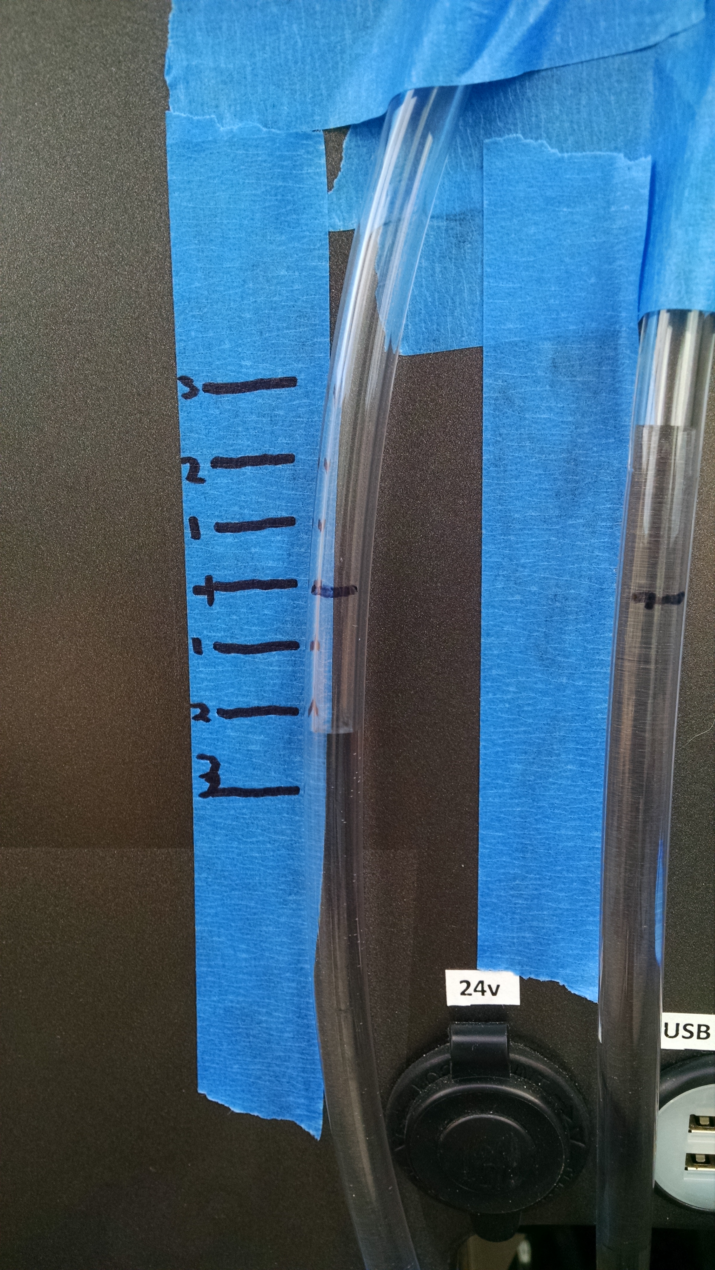
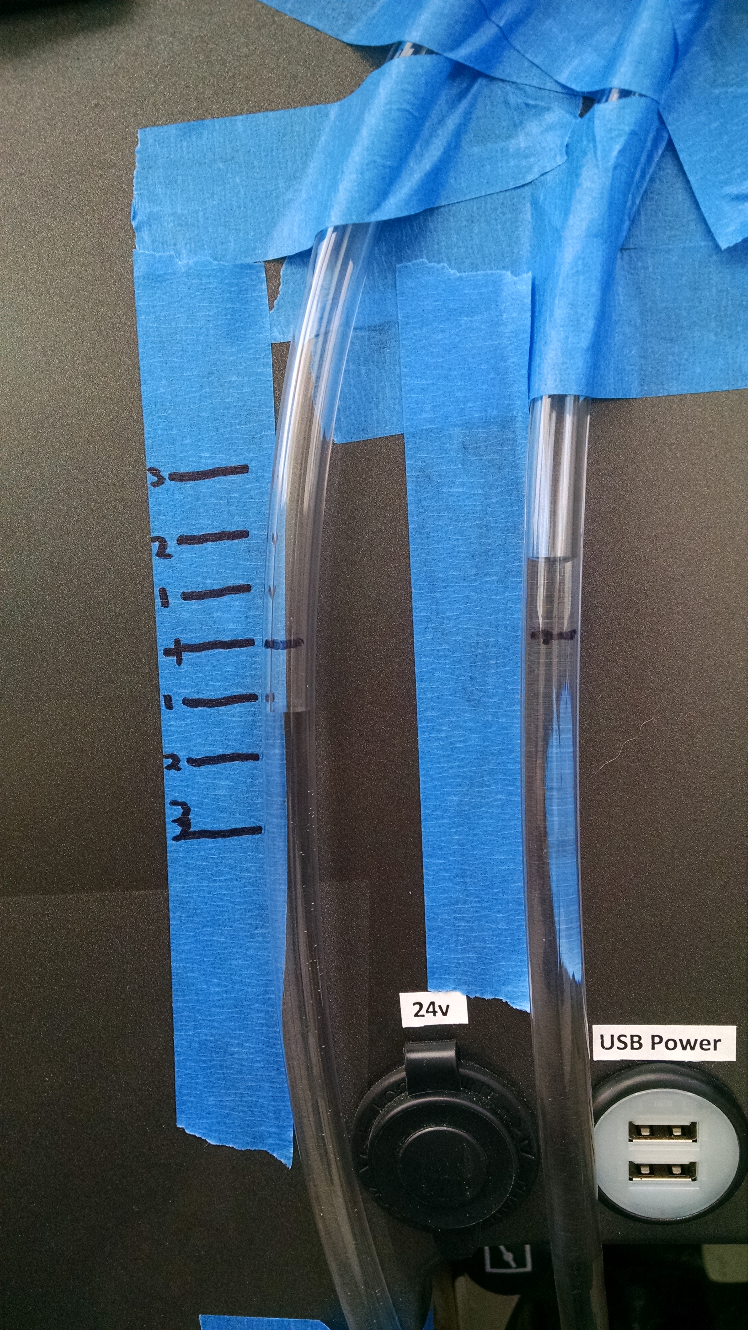
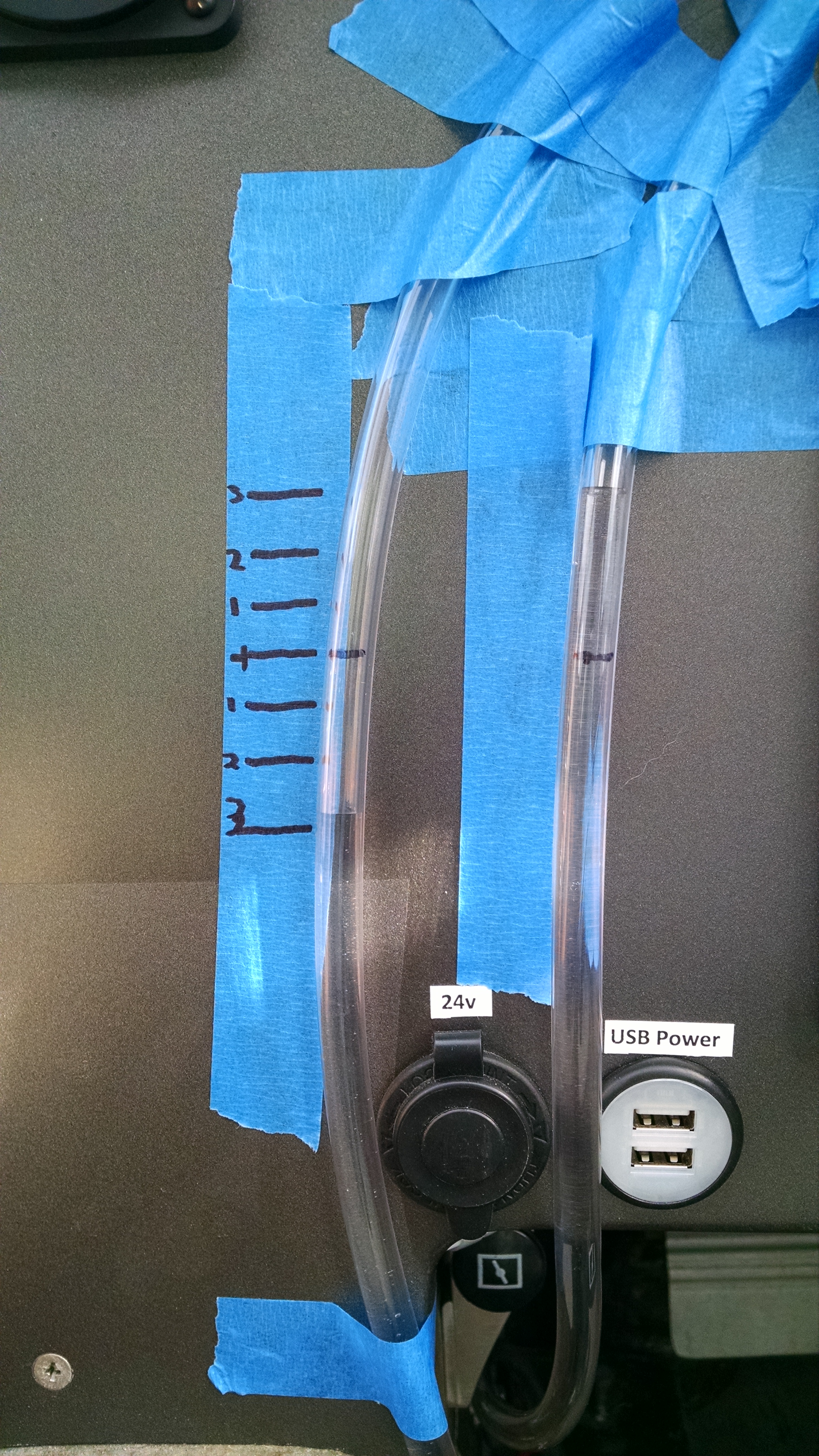
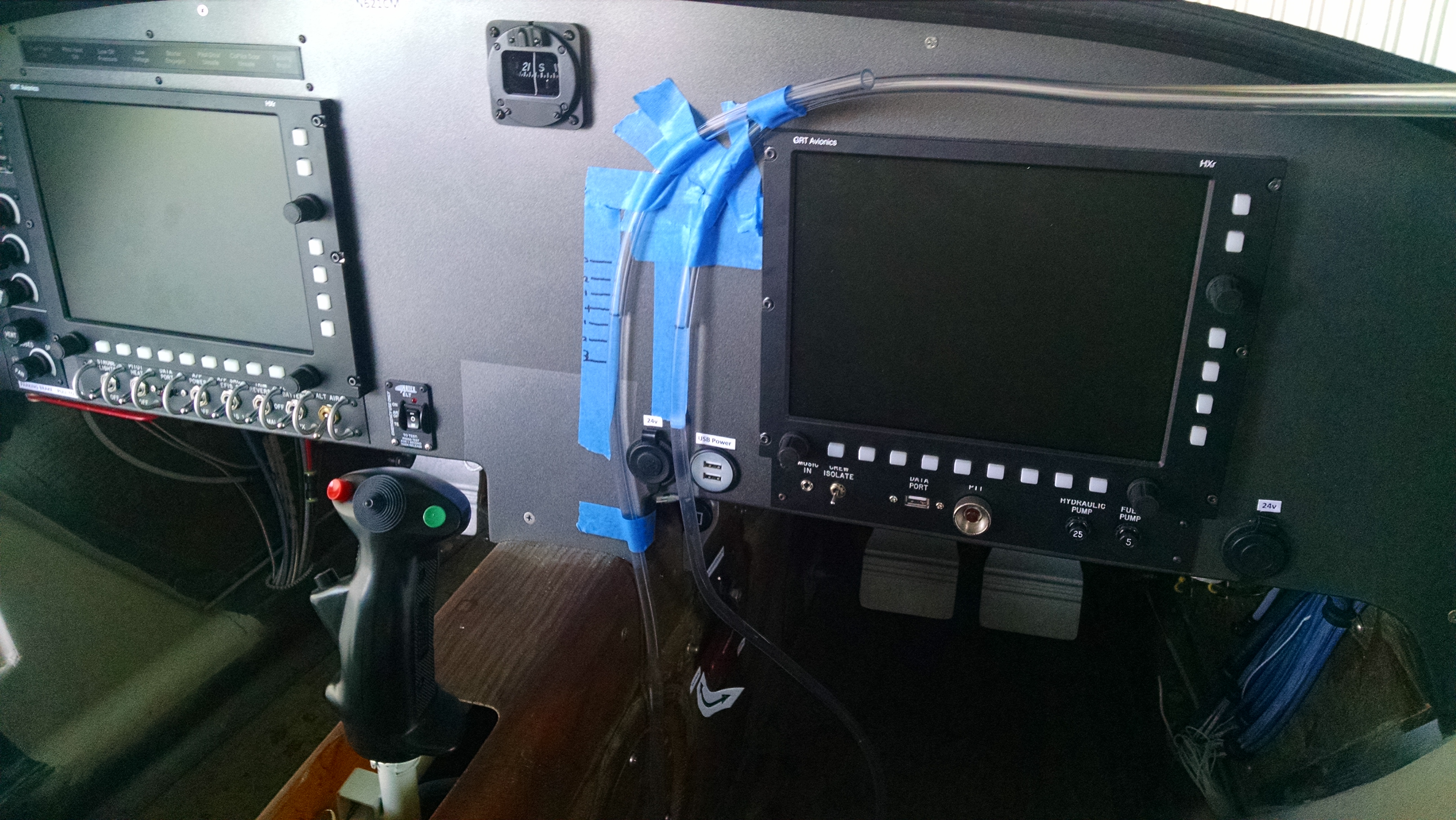
After talking with Rick and Dale (sounds like a 60’s surfer rock duo, doesn’t it?), I decided to build a manometer. AKA, pressure sensitive water level. So I removed the stir stick and hooked up my home made manometer.

Here you go. Tell me that doesn’t scream “Experimental”.

IMG_20150925_132935362

One end is connected to the static port (right tube), the other is open (if you already see the problem, you’re way ahead of me. But I figured it out at Sandy’s Grill over a cider that night).

Sitting on the ground, I made marks to show level and a few other reference marks. When air moves over the static port, if the water level in the left tube goes down, then the port is in a vacuum. If the level goes up, it’s being pressurized.

So here I am at 196 knots and 160 knots over the ground.

IMG_20150924_160551176IMG_20150924_161110900

Vacuum!!!

So I decided to change the shape of the static port from a flat disc to a dome (I’m obviously getting tired at this point) and went up again.

IMG_20150924_173357074

Even more of a vacuum!?!?

That’s when I decided to call it quits.

Because it was Thursday night, I went to Sandy’s Grill (Thursday is steak night there). While I was there thinking about things over a steak ka-bob and an apple cider, I had a couple epiphanies. The problem with the manometer is that it was measuring the static pressure relative to the pressure in the cabin. Which is typically lower than the outside ambient pressure to begin with and at this point is a completely unknown variable. Which means that was a pretty useless experiment to begin with.  The only way a manometer reading could be valid is if I could locate a true undisturbed ambient pressure location for the other end of  the tube.

Second was the modification to the static port. But making it domed shape, I effectively created an airfoil. Like the top of the wing. Which is a low pressure area. Which means it would be creating a vacuum. That is why it showed an even greater vacuum.

So I decided to approach it as simply as possible. There are two primary sensing instruments based on the pitot/static system: altitude and airspeed. If there are no leaks and the instruments are calibrated, then the only variables are the static port location and the pitot tube location. I was careful to locate the pitot tube where the manual specifies which obviously leaves the static port position as the problem.

So all I need to do is get one of those two instruments reading correctly and the other will have to be correct. Because I can’t determine my altitude with any accuracy (without something like a radar altimeter), then I’ll just have to tweak the static port until the airspeed reads correctly. Once the airspeed is showing the correct speed, the altimeter would have to be accurate as well.

Now this makes some pretty big assumptions. I didn’t skimp when I purchased the pitot tube (it cost me about $500) so I’m comfortable it should be creating the correct ram air pressure. I checked the system for leaks so I know that’s good. The last variable is whether the GRT Air Data Computer/Attitude/Heading Reference System (AHRS) is correctly computing the airspeed. The AHRS is a rather complicated piece of electronics and at this point I have to trust it’s doing it’s job.

And finally, since the changes I’ve made to the static port created variations that are expected predictable, then I’m confident that’s where the adjustments need to be made.

So I removed the static port, got a file and started filing down the leading part of the port. I only took able 1/16″ of an inch off (right is facing the front of the airplane).

IMG_20150924_183745396

Then I hooked it up and went flying.
When I crunched the numbers, the indicated airspeed was about 15 knots high.  I made a couple more passes with the file and did another flight. Now it was reading about 10 knots high.

So next I’ll make a couple more passes with the file and try again… and again… and again.  Basically sneaking up on it because I don’t want to go to far. When I get it to where the TAS equals the groundspeed (compensated for winds aloft), then the altimeter should be reading correctly as well. The only way that I can think of to test that is to make a high-speed low pass at the airport. If I do that at a visual height of 50 – 100 feet, then the altimeter should show that I’m flying at the field elevation plus 50-100 feet.

But for now, that will be one of the first things I do when I get back to Panama City.