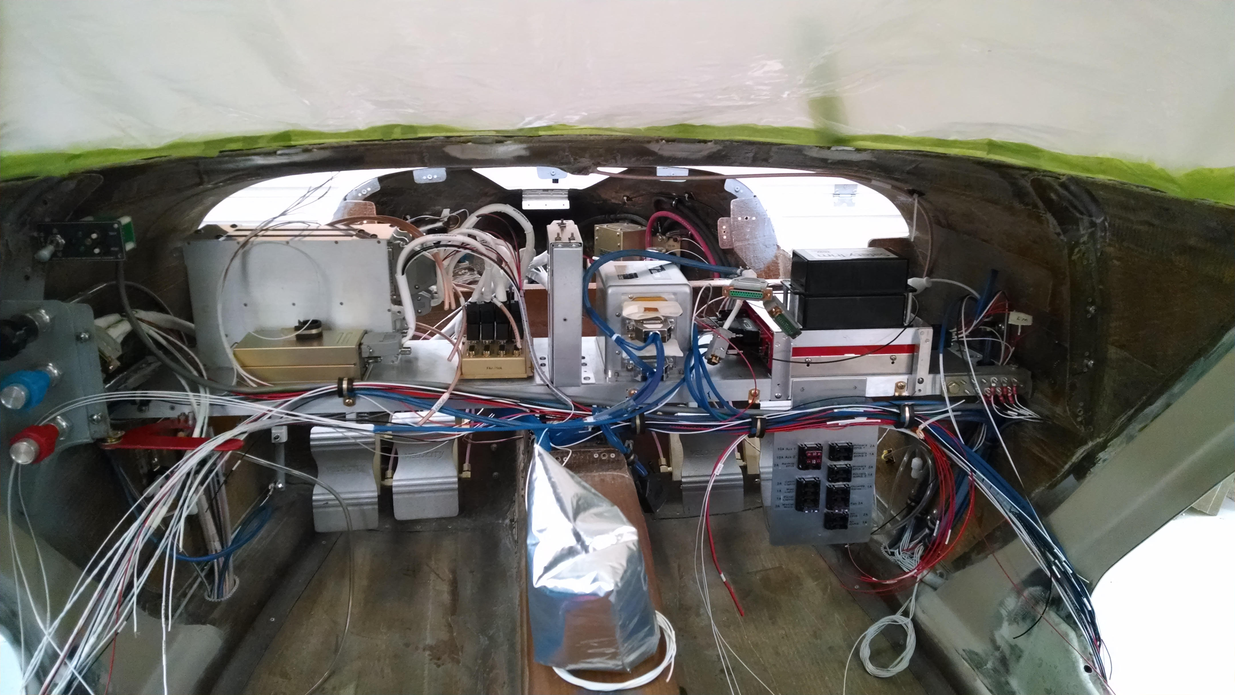
13.7.1 Avionics Shelf

This entry is part 10 of 67 in the series 13 - Electrical / Instruments

One of the traps that you can fall into when building an airplane is to purchase things way before you need it. With electronics, this can be especially troublesome since the radio that you buy today can be antiquated (or obsolete) by the model that comes out 6 months later.

Lately, I’ve been trying to figure out how all the different boxes which make up the avionics suite are going to fit on the avionics shelf. I don’t have most of the equipment yet since I don’t want to buy anything until I absolutely have to have to.

The dimensions are readily available but after spending a few hours drawing and playing with 3D CAD software, I decided to go old-school. I got some leftover blue foam and made mockups of the various boxes.

Here are the two communications radio & single navigation radio (on left), transponder, audio panel, dual AHRS (under audio panel), GPS, two trim controllers and Vertical Power VP-X Pro (under the GPS and trim controllers).

2013-12-05 IMG_20131205_145953_526

After moving things around and not being able to make everything fit, I decided that I needed more shelf space. So I made a sub shelf that will go above the VP-X.

This is the VPX sub-shelf (from the front).

2013-12-06 IMG_20131206_095534_059

Because the trim controllers have adjustments for the trim motor speed, they need to be accessible. So I made a stacked mount for them.  Here is the view of the avionics sub-shelf from the rear.

2013-12-06 IMG_20131206_170639_577

And here is how the avionics boxes will be laid out (for now).

2013-12-06 IMG_20131206_170612_732

13.9.2 Autopilot Roll Servo Wire Routing Modification

This entry is part 9 of 67 in the series 13 - Electrical / Instruments

I couldn’t figure out the best way to route the wires to the autopilot roll servo from the right wiring duct to the servo. I asked Malcolm and he said to bring it forward to the whale tail and then back to the servo. But I wasn’t planning on that long of a run and the wires weren’t long enough. It’s not a huge deal to run new wires but that was a rather circuitous route. I asked about running them directly across but Malcolm wasn’t keen on wires that close to the gear retract cables. So I cut a length of .25″ aluminum tubing and glassed it in position.

Nice, short cable run, protected from any moving parts. Win/win.

2013-11-30 IMG_20131130_153308_3682013-12-07 IMG_20131207_081954_123

13.8.1 Magnetometer connections

This entry is part 8 of 67 in the series 13 - Electrical / Instruments

Now that the magnetometers are mounted, it’s time to run the cables to them.  The supplied wiring harness from Grand Rapids is 20 feet long. The magnetometers are in the left strake. The wires aren’t long enough to run down the right wiring duct so they’ll have to go down the left side duct. I checked with Ben at Grand Rapids and he confirmed that running the wires in the same duct as the communications antennas will not cause any interference with the magnetometers or radios.

Once I got the two harnesses organized, I ran them through the mesh sleeves. Then, because I didn’t want to find out that the antennas wouldn’t fit, I pulled the magnetometer wiring, both com antenna wires and both nav radio antennas at the same time.

Then it was just a matter of terminating the magnetometer end of the wires and connecting them.

2013-12-11 IMG_20131211_113140_3022013-12-11 IMG_20131211_113108_801

13.2.2 / 13.6.2 Aft wiring complete

This entry is part 7 of 67 in the series 13 - Electrical / Instruments

Mostly. 🙂

Just about all the wiring in the aft portion is complete. That is, everything aft of the seats. The engine compartment was completed earlier. It the inside part that had me scratching my head. Lots of wires and trying to decide of the best routing for them.

Here’s the back of the inside:

2013-12-13 IMG_20131213_101952_930a

On the very bottom/center of the picture is the roll trim motor. That’s not wired yet (I said “mostly”).

Above that are the two voltage regulators. One on the left is for the primary alternator and the one of the right is for the backup alternator.

Up the left side are the wiring bundles (blue) for the Engine Information System (EIS), navigation lights and power for the fuel level sending units.

Halfway up on either side are two small black boxes (with two white labels). Those are the fuel level sending units (one for each tank).

On the left side, to the left and slightly above the fuel sending unit is a terminal block for connecting various devices.

Above that (top/left) is the ground block for anything inside the aft cabin.

Here are the two voltage regulators.

2013-12-13 IMG_20131213_172616_308

This the right fuel sending unit and terminal block.

2013-12-13 IMG_20131213_101703_841a

Closeup of the terminal block.

2013-12-13 IMG_20131213_101714_071

From the top:

  • Manifold Air Pressure Sensor Power Supply
  • Manifold Air Pressure Sensor Signal
  • Right Fuel Sender Unit Signal
  • Left Fuel Sender Unit Signal
  • Fuel Sender Unit Power Supply
  • Navigation Lights
  • Strobe Lights

All the way in the top/left is the ground block. This is connected to the ground block on the engine side of the firewall.

2013-12-13 IMG_20131213_172706_284


13.0 Wire Labels

This entry is part 6 of 67 in the series 13 - Electrical / Instruments

Originally I was going to label my wiring using plan English labels. Oil Pressure Sensor, Fuel Pressure Sensor, etc.  But the printable, heat shrink tubing is wicked expensive. And with the longer labels covering the wire, it made wires less flexible.

So I started searching for a different approach.  I found a Navy document that had a section on wire labels. I made some minor changes since I don’t have to accommodate 38 miles of wiring, heat seeking missiles, etc.

This is what I ended up with:

Wire Labels

In this case, the wire above would be for the Autopilot Pitch Servo. Specifically, the power to the Pitch Servo. If the wire were to connect through a terminal, then on the other side of the terminal it would be C2-1B-18.

The only downside to this method is that there is now a document that lists out all of the categories, devices and wires. But now all the labels are a uniform length and relatively short.


13.0 Electrical System Documentation

This entry is part 5 of 67 in the series 13 - Electrical / Instruments

Normally when I create these posts, I use the section number from the manual at the beginning of the title, i.e. “7.8.4 Main Gear Microswitches”. But the electrical system is not really part of the build manual. Chapter 13 is basically “install the electrical system”. 🙂  So lately I’ve been taking the easy way out and using 13.99 for the section number. But I don’t like that since it makes it harder to find posts on a particular topic. And I think that’s very important. So I’ve expanded on the section numbers for Chapter 13.  It’s a work in progress so it will probably grow as I continue working. But for now…

13.1   - Antennas
13.1.4 - Glideslope Antenna
13.1.5 - Marker Beacon
13.1.6 - Transponder
13.1.8 - GPS
13.1.9 - ELT

13.2   - Instrument Panel
13.2.1 - Instrument Panel

13.3   - Electrical System Completion
13.3.1 - Introduction
13.3.2 - Basic Electrical System
13.3.3 - Trim, Speed Brake, & Speed Brake Warning
13.3.4 - Switches and Circuit Protection
13.3.5 - Avionics
13.3.6 - P-Leads

13.4   - Pitot - Static and Vacuum Instruments
13.4.1 - Vacuum System
13.4.2 - Static Port
13.4.3 - Pitot Tube

13.5   - Lighting
13.5.1 - Nav/Strobe Lighting
13.5.2 - Cabin Lighting
13.5.3 - Landing Lights

13.6   - Power Distribution
13.6.1 - Battery 
13.6.2 - Alternator
13.6.3 - GPC
13.6.4 - Starter

13.7   - Avionics
13.7.1 - Avionics Shelf
13.7.2 - Radios (Navigation, Communications, Transponder)
13.7.3 - GPS
13.7.4 - Audio

13.8   - Instrumentation
13.8.1 - EFIS
13.8.2 - Master Warning Annunicator
13.8.3 - EIS

13.9   - Control
13.9.1 - Trim
13.9.2 - Autopilot

13.2 Instrument Panel Layout

This entry is part 33 of 67 in the series 13 - Electrical / Instruments

One of the huge pitfalls that can ensnare a builder is what I call “panelitis”.  That’s when you start building the airplane and at the same time you begin designing and purchasing the components for the panel.

The problem with purchasing your radios and GPS, audio panel, instrumentation, etc., is that 1) the warranty will expire WAY before you get close actually putting it in the airplane and 2) technology will make the stuff you’re already bought obsolete.

Which is why I avoided anything to do with equipment purchases for the panel.

A few years ago I bought the EIS (Engine Information System) because I was installing the engine.  Then 8 months ago, I bought the Vertical Power VPX-Pro power distribution system because it was time to actually start pulling wires. So you see, I’ve been doing good. 🙂

From the beginning, I was planning on a “glass panel”. This is where the traditional “six pack” of gauges are replaced by an electronic display.  Just about every aircraft made today has this type of display.

Cessna-172-Instrument-Panel  vs.  c-172-g-1000-glass-cockpit

The vendor I was going to use is Grand Rapids Technologies. They’ve been making EFIS’s (Electronic Flight Information Systems) for a while and they have an excellent reputation. At the time, they had a couple different sizes of displays and I made a couple different layouts.

Panel4b

This is what I would call “rev 1”. The vertical dashed line indicates the center of sight from the pilot’s seat. Here I’m using two screens (one for flight information and one for engine data), a traditional radio stack, a circuit breaker panel and a trio of old school gauges as backup.

Panel4c

This layout is similar to rev 1 but uses slightly larger screens in a side by side configuration. Another builder, Terry Miles, told me that reaching across with your left hand to work your primary radio can be really annoying. He suggested positioning it for easy left hand access.

I had actually purchased the backup instruments from my good friend Albert about 4 years ago. But then… technology advances. Companies started coming out with miniature EFIS that had built in batteries. This would eliminate the three gauges. So I sold the backup gauges (and even made a couple dollars). Over time, the backup EFIS units have gotten smaller and cheaper.


Panel4a

This is rev 3. Just like rev 2 except the backup gauges are replaced with the small, backup EFIS.

Then about a year and a half ago, I heard that GRT was coming out with some really new equipment. You’ll notice that all the designs that I’ve done have two screens. That’s because one of them is for flight information and the other is for engine information. I’ve always felt this is kind of wasteful. Well the new EFIS allows you to use an Android tablet as the second display. And… here’s the best part:  remote avionics. Which means that the radios, GPS, transponder and audio panel will no longer be taking up panel space. They will be mounted behind the panel and controlled from the EFIS.

So I made another panel layout.

Panel5

The new HXr screen is much bigger and I eliminated the circuit breaker panel because the VPX is controlled by the EFIS (or the tablet). This makes for a much “cleaner” looking panel. As soon as heard about the new EFIS, I got a quote. Huge savings over what I was planning. Then every time I stopped by at Sun-n-Fun or Oshkosh, I would have the quote updated.

Oh yeah, they also came out with their own autopilot. Which was a fraction of the cost of the S-Tec 55x that I had bought which was going to be a freakin’ nightmare to install.

See how waiting is a good idea?

So about 6 months ago I ordered the EFIS and auto pilot servos. I didn’t really need the EFIS yet, but it’s the only way to see what’s happening with the VPX power system.

So now it’s present time.

I’ve been trying to decide on whether or not to wire everything myself or use the Approach FastStack Hub. Normally, some of the wires from one device may go one, two, three, or more other pieces of equipment. So you have 25 wires coming out of one box with 10 going to box A, 5 going to box B, and 15 going to box C. With the FastStack Hub, everything connects to the hub. And the hub takes care to sending what to where. I asked around and everyone that’s done it both ways all said that would use the hub in the future.

I called Tim at Approach FastStack, told him what I was doing and he got to work.  A day later, I got “the call”.

So here’s the deal: All the radios, GPS, transponder, autopilot… EVERYTHING communicates with the EFIS. I’ve got about 11 devices in total that talk to the EFIS using serial ports. And the EFIS has eight serial ports. Don’t ask me how, over the last 18 months, I’ve gotten multiple quotes from GRT for a configuration that simply won’t work.

I called GRT and they confirmed what Tim had discovered. The only way to “fix) this is by adding another EFIS screen (8 more serial ports). The guys at GRT felt pretty bad that nobody ever noticed this so they gave me a pretty decent discount on the second screen. It still stings. And I’m going to lose some of the panel space that I would have been able to play with… and for a screen that I really don’t need… I just need the serial ports that come with it.

But at the end of the day, I’m still better off than I was 2 or 3 years ago.  (yeah, I’m trying to be positive)

Back to the drawing board for a new layout.

Electrical System - New


13.3.5 Avionics Wiring

This entry is part 34 of 67 in the series 13 - Electrical / Instruments

As I mentioned before, I have elected to go with the FastStack wiring Hub for the avionics. While the wiring and termination of the all the connectors is something I’m very familiar (and comfortable) with, the volume of it was a bit daunting.

This is the wiring for a Beech Duke.

duringduke4

The Approach FastStack box arrived today.

2014-02-10 IMG_20140210_194733750a2014-02-10 IMG_20140210_194740451

I’ve got to say this is some of the best documentation I’ve run across in a long time. Each cable is labeled and comes in its own bag with QC documents and configuration.

2014-02-10 IMG_20140210_195055238a

The manual is also very clear and well laid out.

2014-02-10 IMG_20140210_194842378_HDRa

In short, this should make the avionics wiring significantly easier.

13.9.2 Auto Pilot Pitch Servo Mounting

This entry is part 35 of 67 in the series 13 - Electrical / Instruments

I’ve already installed the autopilot roll servo in the back of the cabin. Now it’s time to install the pitch servo.

First, I have to figure out the best location. After talking with Malcolm, I decided to put it on the right side of the canard.

2014-02-07 IMG_20140207_155850870a

I made a mock bellcrank out of cardboard to determine how long the bellcrank              needs to be. My goal was to try and keep it from infringing on the avionics shelf area.

2014-02-08 IMG_20140208_085255315a

After playing around with this bellcrank, the linkage, and some basic math, I determined that it wasn’t going to be a very big bellcrank.

I talked with Malcolm and he recommended cutting a notch in the canard so the bellcrank doesn’t have to move so far aft.

I contacted my friend Robert who fabricated the parts for my nose gear door mechanism and sent him the drawings for the bellcrank.  As usual, he came up with some really good changes.  While we were talking, I mentioned my frustration about drilling holes through the center of a shaft. He said “I can fix that”.  I figured that he would tell me some secret about how to drill holes.

About a week later, he called and I went to pick the bellcrank. Not only did he make me a bellcrank, but also a fixture to clamp it in place  and align the drill bit!  Sweet!!!

2014-03-01 20140301_161653

Here’s a dry fit in about the location I think the servo will end up.

2014-03-01 IMG_20140301_162830919_HDRa
Here’s the bellcrank clamped in place with the drill fixture.  I miscalculated the length of the bellcrank arm and had to drill another hole in the bellcrank arm. Once I was happy with the location, I drilled out the holes. And they were perfectly through the center of the torque tube.
2014-03-02 IMG_20140302_170725453a

I made a pair of hardpoints out of aluminum and used structural adhesive to bond them in place.
2014-03-03 IMG_20140303_145411783a2014-03-03 IMG_20140303_145423987a

To make sure that I’m not going to go over-center on the servo, I made a protractor that allows me to measure the rotation of the bellcrank. With this, I was able to determine that I was about 10 degrees under the maximum rotation without going over-center.

2014-03-03 IMG_20140303_145510165a
Next, I trimmed off the excess metal of the bellcrank and painted the parts.
2014-03-04 IMG_20140304_074544052a

Another dry fit checking the motion.
2014-03-04 IMG_20140304_075927686a 2014-03-04 IMG_20140304_075930670a

2014-03-04 IMG_20140304_075951917_HDRa 2014-03-04 IMG_20140304_080013137_HDRa

Covering the hardpoints with 2xBID
2014-03-04 IMG_20140304_101547947a

Final installation (I still have to replace the phillips head screws and replace them with drilled head AN3 bolts and safety wire them).
2014-03-05 IMG_20140305_084726425_HDRa

13.7 Avionics and Wiring

This entry is part 36 of 67 in the series 13 - Electrical / Instruments

It’s time to start actually mounting avionics.  I’ve held off as long as I could because once the avionics shelf goes in, getting to things gets harder.

Prior to receiving all the various boxes that go on the shelf, I used blue foam cut into the correct size and shape to determine where everything would go.

2013-12-06 IMG_20131206_170612_732

But now it’s time to start mounting things. Some builders will wire the components up on the bench first. But I couldn’t imagine running all the wiring for that temporarily.

Here’s the two comm radios and single nav radio. I made the brackets which combine the three radios into a single unit for mounting.

2014-03-20 IMG_20140320_142211166a

Then I added the transponder (which actually attaches to a mounting tray.

2014-03-20 IMG_20140320_144025277a

Next I put in the mounting tray for the FastStack wiring hub that all the boxes will connect to.

2014-03-21 IMG_20140321_065845776a

And finally the Audio Panel. The AHRS, VPX, and trim controller sub-shelf had already been mounted.

2014-03-21 IMG_20140321_084535334a

Then I installed the shelf into the plane to make sure everything still fit.

2014-04-06 IMG_20140406_170850589a

Now it’s time to start pulling wires.

The largest of the wiring assemblies were for the EFIS screens and the Audio Panel. So I put those in first since they have the largest bend radius.

2014-04-15 IMG_20140415_203514234_HDRa

One of the things I was worried about was the connectors for the EFIS screens. The extend towards the avionics shelf and I was worried about whether the installed avionics boxes would interfere with the connections. So I came up with a rather low-tech approach.

I cut a piece of card stock the size of the EFIS screens and cut out where the connectors would be. Then I taped some long stir sticks that ended on the panel mounting screws.

2014-04-16 IMG_20140416_105635499a

Then I just put the ends of the stir sticks on the panel mounting holes and I could see where the connectors would end up.

2014-04-16 IMG_20140416_105707789a

This confirmed that the connectors would not interfere with any of the existing equipment.

At this point it was time to start pulling the rest of the wires. The FastStack Hub greatly simplified the whole process. But even with that, there are still a bunch of wires.

2014-04-17 IMG_20140417_180210346_HDRa

After a while, it starts getting a little better looking. But still a long way to go.

2014-04-19 IMG_20140419_110502292a

I felt like I should make sure the panel cutouts for EFIS screens, switch panels and power ports were correct (I had checked them individually but not all at the same time). So I made a stand to hold the panel up and installed all the components.

2014-04-20 IMG_20140420_175307644a

The only thing left to do is mount the Backup EFIS.