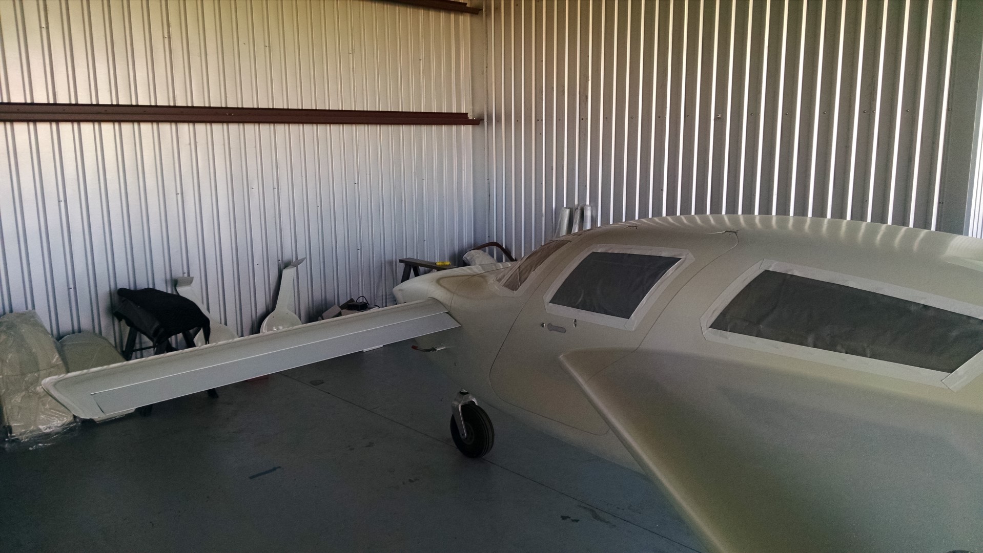
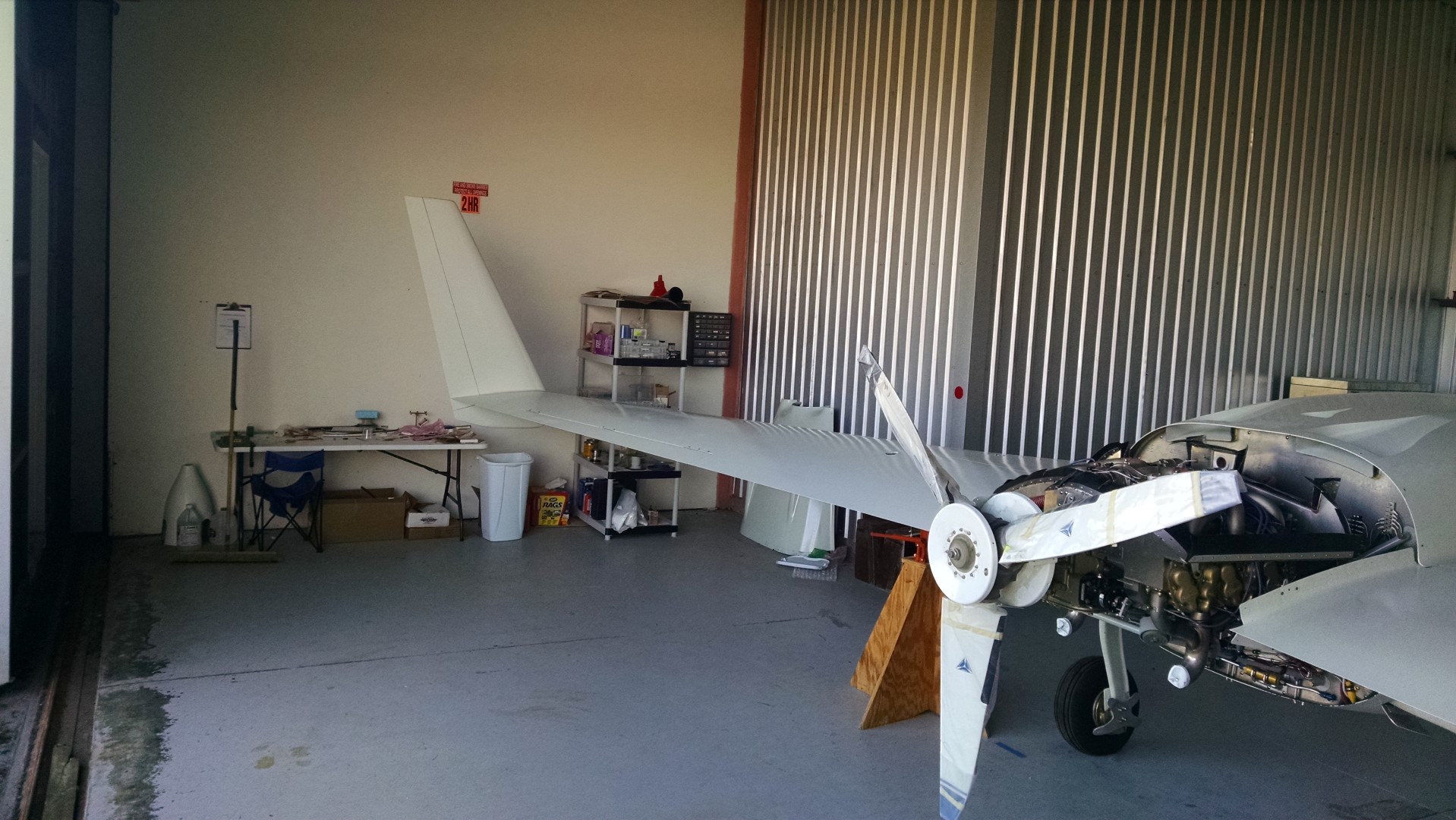
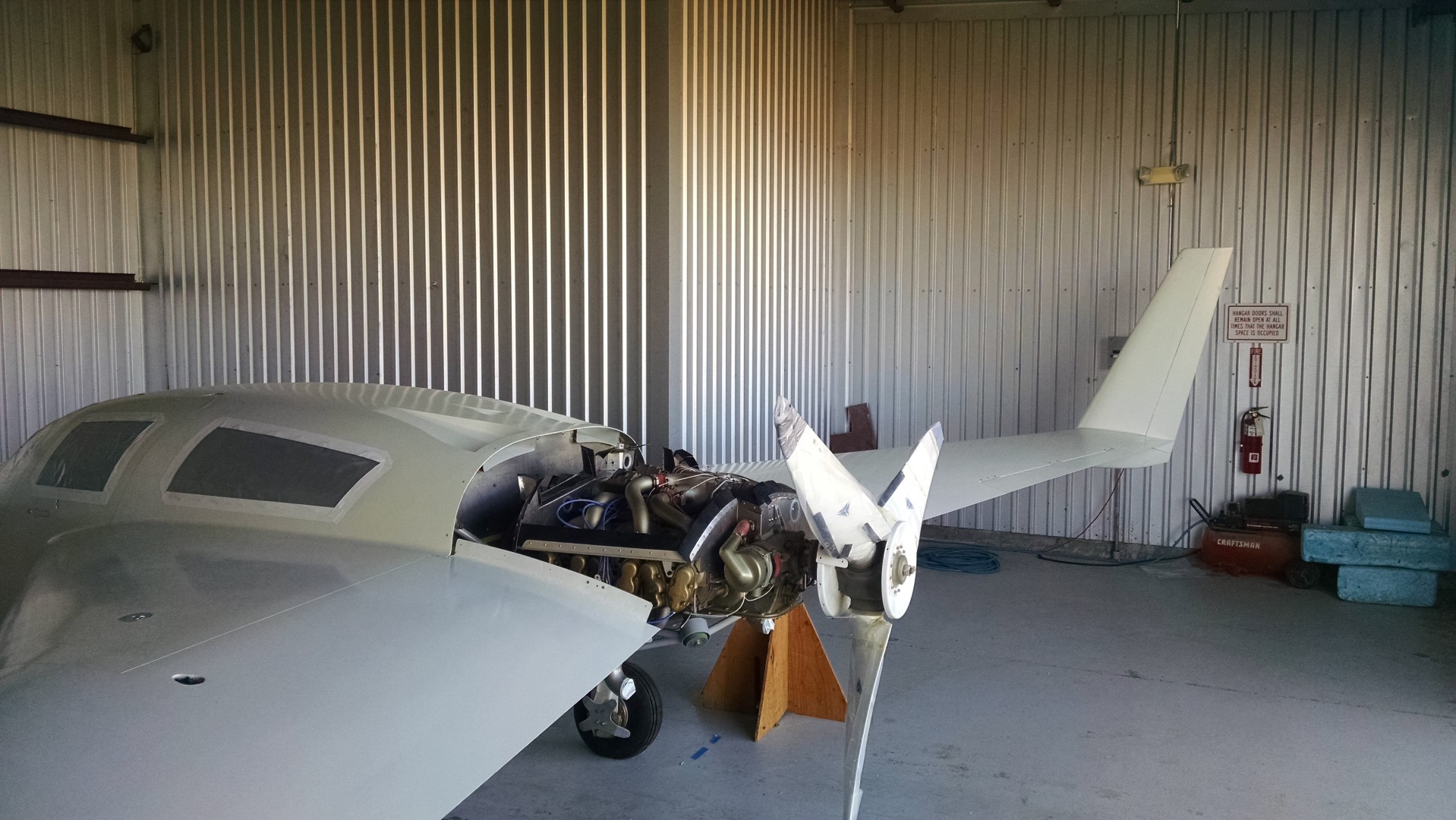
14.99 Engine Run III

This entry is part 31 of 38 in the series 14 - Final Assembly / FInishing

I’m pretty sure that the fuel metering is off since the fuel flow is a bit high and I can’t keep the engine running below 1,000RPM. But in order to adjust the fuel metering, I need to verify that the tach is reading accurately.  So I borrowed an optical tach and did another engine run.

So with Malcolm holding the optical tach, I ran the engine at a couple power settings and the panel was showing the exact same RPM as the optical tach.

2015-03-07 1555 IMG_20150307_155513645

While I was doing that I also tested both alternators. The primary alternator was working fine but the secondary alternator was not producing power. While troubleshooting, I discovered that the co-pilot side EFIS didn’t even show the secondary alternator.

EFIS-1 on the left and EFIS-2 on the right

2015-04-01 IMG_20150401_1329297272015-04-01 IMG_20150401_132936036

After a bit of research, I discovered that there is a software update for the EFIS that fixes this issue. So that will get done of the next trip down.  I doubt that is the reason for the inoperative secondary alternator but I’ll tackle that after the software update.

14.99 Contact!

This entry is part 29 of 38 in the series 14 - Final Assembly / FInishing

So at this point, the wheels have been aligned, the fuel tanks have fuel in them, the electrical system is complete. In short, there’s nothing that needs to be done to start the engine.

So I drained the oil down to 8 quarts (I had overfilled it as part of the long-term storage), pulled the upper (desiccant) plugs and removed the covers from the exhaust and intake.

Malcolm came over to act as a pair of eye watching the engine for any problems (with the engine in back, you can’t see it from the cockpit). We pushed the airplane out of the hangar and with the mags off, I cranked the engine for about 5 seconds to get oil circulated.

Then I installed and connected the upper spark plugs, looked things over one last time and hopped in. Malcolm was positioned just by the left wing with the fire extinguisher (just in case). I primed the engine and Malcolm say fuel coming from the bottom of the engine. We looked things over and discovered the fuel supply fitting at the forward baffle was loose. Considering all the fuel fittings, I’m surprised that I only missed one.

I tightened it and tried priming the engine again. No leaks this time.

Then I turned the left mag on a cranked the engine. It tried to catch but never really started. Malcolm noticed that only one side seemed to be firing. Tried a couple more times and it finally caught and started. But it was rough. And it stalled out after about 10 seconds.  I noticed that the EGT for the #4 cylinder was non-existent. So I guessed that the bottom plug had gotten fouled due to oil getting into the cylinder from being overfilled.  When I went to remove the ignition wire, I discovered it was loose. When I checked the other lower plugs, they were all loose. However long ago that I had built the baffling and removed and reinstalled the ignition wires to route them through the baffle, I never tightened them.

So a few minutes later, they were all tight.

Back in the cockpit, and it started right up.

Run #1

2015-03-06 1632 Image00512015-03-06 1633 Image00522015-03-06 1633 Image0053

I ran the engine for about 10 minutes until the oil got up to about 320 degrees and the EGTs all came up. I noticed that the #4 EGT was still reading zero. The CHT was reading about the same as the other 5 cylinders so I knew it was making power. Once I shut down the engine, a quick check with the IR thermometer showed the same temp and the other cylinders. So it had to be a loose connection or a bad EGT probe.

But it was late and it’s always good to leave on a high note. So we put the plane back in the hangar.

The next morning, I replaced the connectors for the #4 EGT probe and we pushed it back out for run #2.

Run #2

2015-03-07 1533 Image0056 2015-03-07 1534 Image0057 2015-03-07 1531 Image0054 2015-03-07 1531 Image0055

Engine started right up.  But it’s still not quite right. I called my A&P/IA friend and he said that it was probably going to need to adjust the fuel injection system. Even though the engine shop ran the engine after rebuilding it and would have adjusted it, he said that it’s not unusual to have to do again. So that will happen on the next trip down.


14.1.10 Calibrating Fuel Tanks

This entry is part 28 of 38 in the series 14 - Final Assembly / FInishing

This turned out to be a real pain.

I was expecting a relatively straight-forward process.  Something along the lines of add 5 gallons, press a button, repeat, etc.  That’s why I added the shut-off valves on the last trip.

Then I discovered that my fuel probes have five “setpoints” (Empty, 1/4, 1/2, 3/4 and Full). Which means that I have to fill the tanks to determine how much they hold, empty them, then refill while defining the setpoints.

So I removed the lines between the strake tanks and the sump, attached four feet of flexible line to the strake tank, ran the line out the main gear opening and attached the valve at the end. This way I can drain the tanks without too much fuss.

2015-03-03 1449 IMG_20150303_144958069

I borrowed eight 5 gallon fuel cans and had them filled at the FBO (I’ve been hoping for 45 gallons per side, but I didn’t want to get more fuel than necessary so I started with 40 gallons) Then carted them over to the hangar.

2015-03-04 1245 IMG_20150304_124539533

Then I started filling the tank and checking the level after each 5 gallons with my 12″ scale.

2015-03-04 1245 IMG_20150304_124557554

And 40 gallons just barely fit.  A bit disappointing since I was hoping for more capacity.  So I drained the fuel out… Which took about 7 minutes per 5 gallon can (so about 45 minutes to drain a tank). And that’s when I realized that the plane wasn’t level.  I had neglected to tighten the collar on the right jack and it leaked down so that the right wing was low. I raised the jack until the plane was level and then moved over to the left side. After putting in all 40 gallons, I still had about 1/2″ left. So back to the factory to borrow another 5 gallon can, over to the FBO to get it filled, back to the hangar and poured it in the left tank. It didn’t take much before it was full but it looks like just shy of 42 gallons.

Then I drained out the fuel and refilled defining the fuel probe setpoints with “Empty” at 2 gallons, 1/4 at 10 gallons, 1/2 at 20 gallons, 3/4 at 30 gallons and “Full” at 41 gallons (although the probe looks at anything over about 35 or so as full).

Then I drained the left tank and refilled the right defining the setpoints the same as the left side. When I was finished, I determined the right tank holds just a little more than 41 gallons.  So I decided to call the fuel tanks at 41 gallons.

Then I drained the right tank (for the last time), reconnected the strake to sump fuel lines and dumped the fuel back in. After a short period the fuel equalized between the two tanks and I was done with th  at task.


11.1.99 Cowling Baffle Treatment

This entry is part 15 of 17 in the series 11 - Fairings

I’m not using the standard Velocity cooling plenum.  I decided to use a more traditional approach where aluminum baffles create a box that mates with the upper cowling to create the high-pressure plenum.  The interface between the aluminum baffles and the inside of the cowling is a flexible baffle material that creates a relatively airtight seal.  On most other planes the cowling is sheet aluminum and the flexible baffle will slide up against the cowling.

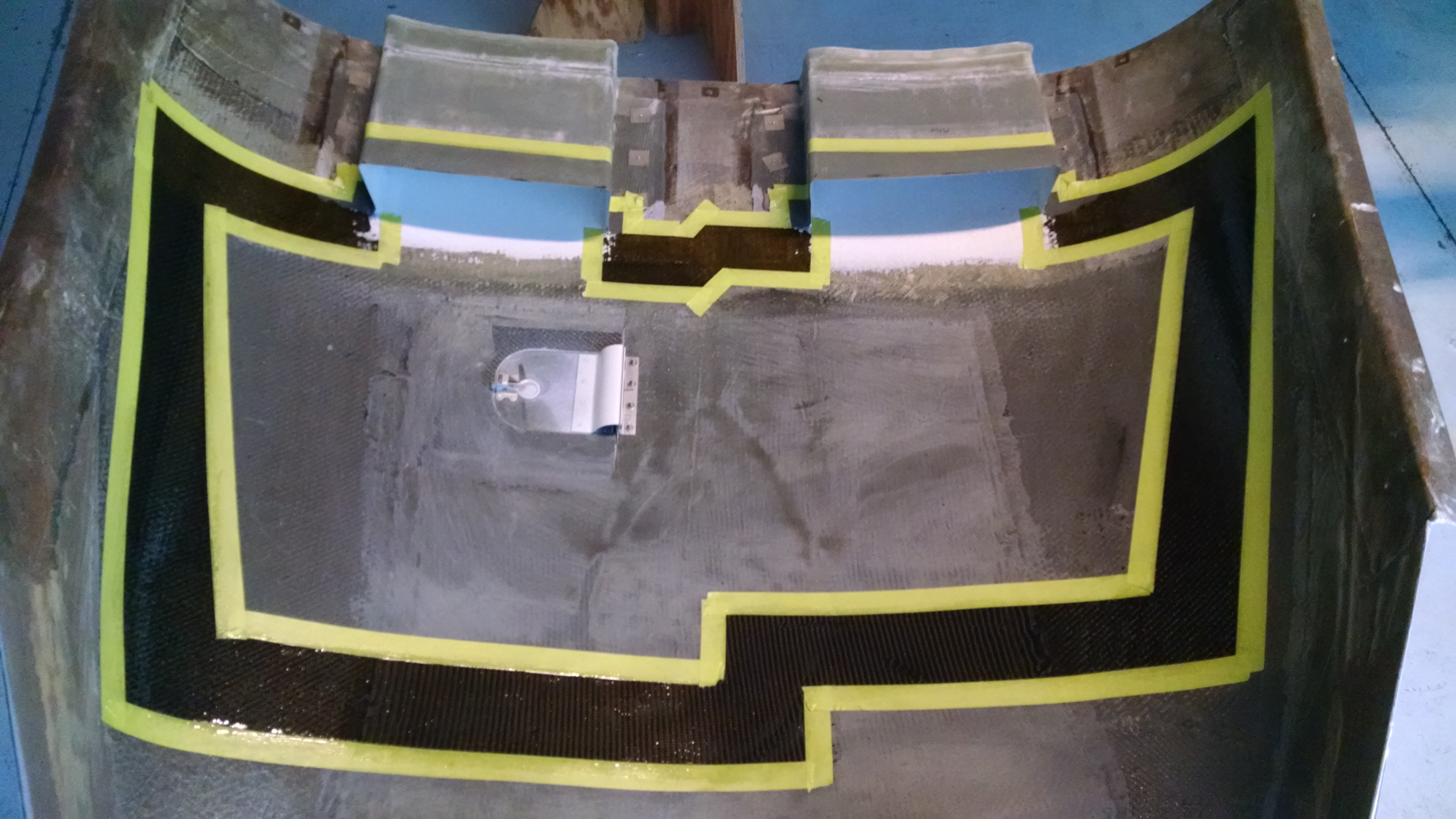
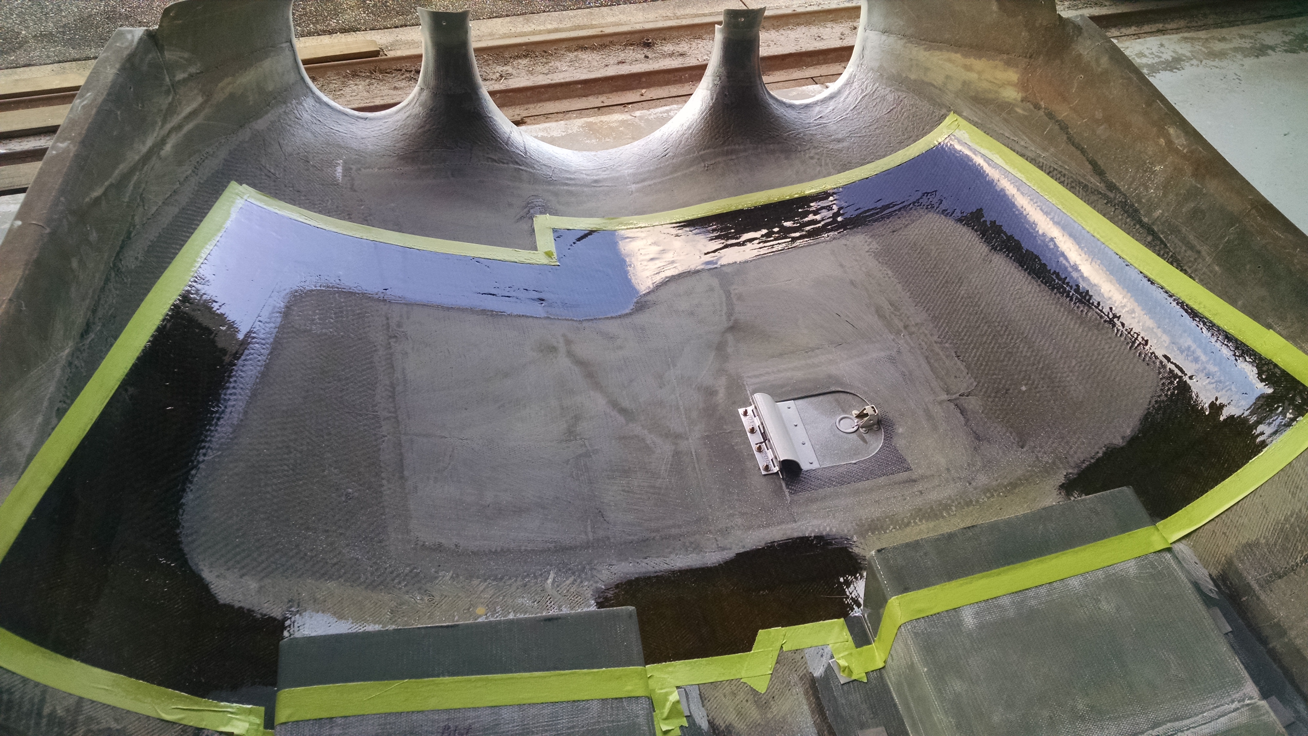
But my cowling is a rather course fiberglass. So to allow the flexible baffle to slide, I decided to create a smooth surface on the inside of the cowling… but only where the baffle will contact.

I sanded down the inside of the cowling where the baffle material will contact the cowling. Then I used masking take to define the area and painted on epoxy.

2015-03-03 1829 IMG_20150303_182934107

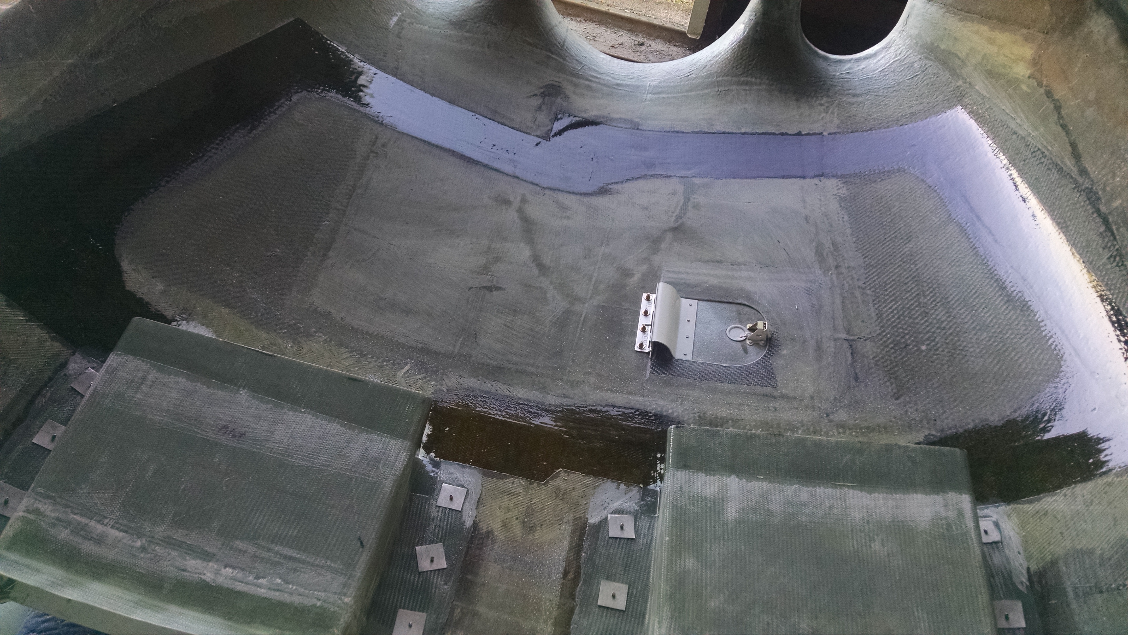
Once it dried, I removed the tape over the inner area, sanded the epoxy and painted on a second coat.

2015-03-04 1021 IMG_20150304_102108196

Now (hopefully) the flexible baffle material will slide as needed.

2015-03-05 0740 IMG_20150305_074025685

10.1.3 Aerodynamic Trim (Sparrow Strainer)

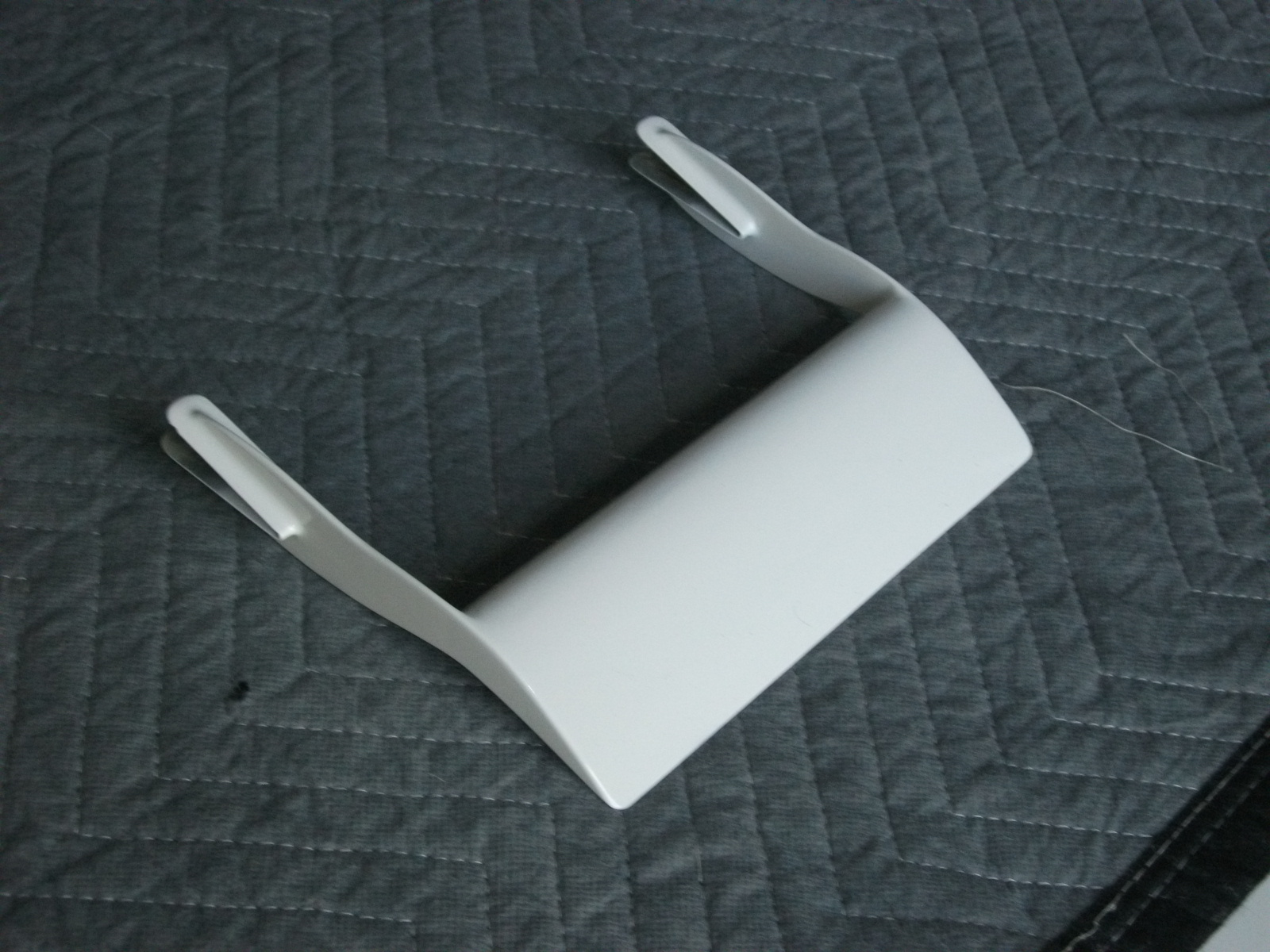
Over the years, whenever I was waiting for something to cure or dry, I would sometimes spend a minute or two on the sparrow strainer.  This is a small inverted airfoil that attaches to one of the elevators. Just like the vortilons, when it was time to finish them, I let Malcolm do it.

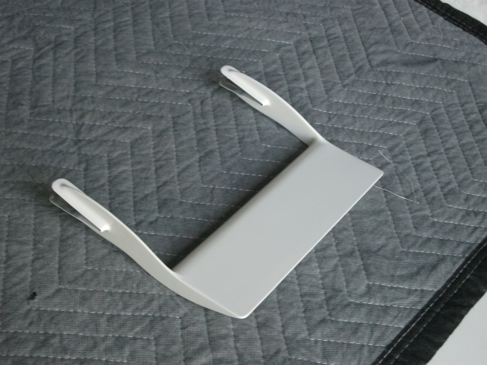
Before starting the finish work, he created a pair of flanges where it attaches to the elevator. Once the flanges were done, he began the sanding, filling, sanding filling process. The the gray primer, more filling and sanding and finally the white primer.

Here’s the end result.

SS 1 SS 2

It will be attached to the inboard end of the right elevator but like the vortilons, I’ll wait until I’m closer to flying before attaching it permanently.

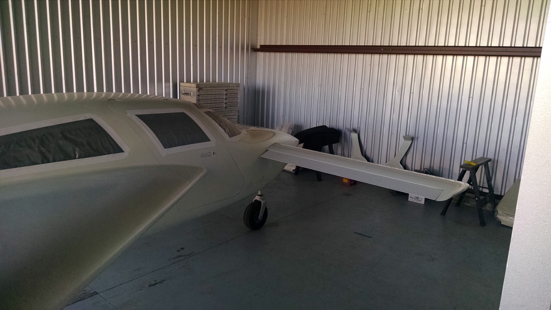
Here it is dry fitted.

SS 3

14.1.7 Vortilon Installation

This entry is part 30 of 38 in the series 14 - Final Assembly / FInishing

Vortilons are small tabs which extend forward from the leading edge of the wings. The word actually comes from two words: Vortex and Pylon. Here’s some aerodynamic science for you:

Vortilons officially first appeared when Douglas was developing the DC-9.  As is typically the case, rather than re-invent the wheel, previous technology and parts are used to speed up development.  In the case of the DC-9, Douglas engineers, decided to use the same wing design as the DC-8. The difference between the two is that the DC-8 had four engines under the wing (on pylons) where the DC-9 had them on the tail.

When they started testing, the engineers discovered that the wing had significantly less lift at low speeds (landing and takeoff) than the DC-8 wing. Since the only difference in the wing design (other than the engine location) were the pylons, they installed just the engine pylons under the wing.  And the lift returned! So the engineers made the pylons shorter and shorter until the lift diminished.

The result became what is now known as a vortilon.

What happens is with swept wing designs (although similar behavior can also occur on non-swept wings), as the angle of attach increases, the flow of air begins to move span-wise (toward the side) as opposed to chord-wise (front to rear).  One of the solutions is to install a fence.

Mig-17 with stall fences.

MiG-17F_Top_View

This prevents the air from moving towards the wingtip. The down-side to stall fences is that while they are only needed during high angles of attach (landing and takeoff), they incur a permanent drag penalty.  Anything sticking out creates drag.  And drag reduces speed.

Vortilons create a rotating spiral of air (vortex) that acts as a stall fence. But they are only doing this at high angles of attack. During low angles of attack, the vortilons aren’t doing much of anything.  Think of vortilons as stall fences that mostly retract when not in use.

Here’s a Starship (because, you know, they’re cool) where you can see four vortilons on the lower, leading edge of the wing.

0902020

The vortilons which come with the kit are rough fiberglass and about the same size. Because this is a highly visible, finish type part, I deferred it to the guru of all things finish (Malcolm).

Here is a picture of a set of vortilons (from Jorge Bujanda’s site) after being trimmed down.  The size goes from large to small as they go inboard to outboard.

vortilonsfinalshape

Then they have to be filled, primed, sanded, filled, primed and painted.

Vorts 4 Vorts 3

Now they do stick out a ways, so it would be real easy while working on the plane to run into one and break it off. So I’m not going to install them until I’m ready to fly. But the positioning is rather important. The location is easy to measure. Just measure out from the wingroot 18″, then 36″ more and then another 36″.  Getting them aligned is another story. For that Malcolm has a template he created.

2015-03-03 1443 IMG_20150303_144339010

First a mark is made on the leading edge. To get it perfectly on the leading edge, I kinda made a tool.

2015-03-03 1453 IMG_20150303_145310291

Then I placed the pencil against the leading edge with a level. While keeping the level/pencil perfectly plumb, I moved everything across the leading edge of the wing. The result is a perfectly straight line which is exactly on the leading edge of the wing.  Now I probably didn’t have to be that precise, but it wasn’t that hard.

Next the template is aligned with the mark on the leading edge and rolled under the wing.  Then simply mark the wing on that line.

2015-03-03 1448 IMG_20150303_1448591032015-03-03 1443 IMG_20150303_144355552

Now when it’s time to install the vortilons, I just have to line them up with the mark.


8.1.2 Main Wheel Alignment

This entry is part 6 of 8 in the series 08 - Wheels / Axles

This is definitely a two-person job.
The wheels on the main landing gear have to be aligned.  Simply put, they need to point slightly in toward the nose. Here’s the procedure:

  1. With the plane on the ground, roll it backward 15′ and then forward 15′.
  2. Using a plumb-bob, define the centerline of the fuselage by marking a point on the floor at the nose and the center of the prop at the rear.
  3. Measure out from the centerline to the outside of the left and right wheels.
  4. Measure out from the centerline at the nose left and right the distance obtained from the previous step.
  5. Using a wicked-ass long I-Beam, place it against the tire and see what distance it is from the centerline at the nose. It should be 1″ (closer to the nose) than the measurement from step 2.

To change the toe-in, shims are placed between the axle mounts at the front or rear depending on whether you want to move the line in or out. And you have to jack the plane up to do this. Which means when you put it back on the ground, you’ve got to do the 15′ back and forth rolling thing.

Malcolm swore that the geometry of the landing gear is such that there won’t be any difference in the measurements with the plane on the ground or on jacks. I didn’t buy that. So we tested it. Measured the alignment on the ground and then jacked up with the wheels off the ground.  Exactly the same. That’s going to save a ton of time!

The next deviation is to not trust the tire being perfect. Instead of placing the alignment device (wicked-long I-beam) against the tire, I used a block of 1″ x 2″ x 6″ aluminum that allowed me to use the metal wheel as the basis for the measurement.

Then I didn’t have a long I-Beam, so I used my 2′ long laser level.

I held the laser level against the block which was against the wheel while Malcolm marked where the laser hit the line at the nose. It looking about 1″ of toe-OUT on each side.

So I pulled the two rear mounting bolt and put in a washer. That got one side close but the other side went in the opposite direction!?!?  Pulled the washers on that side, put it back together, checked it again and it was almost where it needed to be in the first place. Then I discovered that by changing order that the bolts were tightened changed the results wildly.

I completely removed the axle assembly and discovered the gear leg did not have a flat surface in the first place. The result it that I was trying to attach a flat object (axle) to a rounded surface (gear leg). I could have played with the torque on the bolts and the order that I tightened the bolts until I got it where I wanted it, but then a bump could move it out of alignment.  So I mixed up some epoxy/cabo, applied it to the gear leg and bolted everything back together. Once it cured, I had a perfectly flat mounting surface.

New, flat mounting surface.

2015-01-19 0926 IMG_20150119_092606851

After that it was just a matter of determining the correct shims for the two wheels to get the required 1″ of toe-in.

Once that was done I could repack the wheel bearings, bolt together and safety wire the brakes and wheels.

No pictures of the process since there were only the two of us and I was holding the laser and Malcolm was marking the dimensions.

Brake calipers torqued and safety wired.

2015-03-02 IMG_20150302_100351757

Disc bolted, torqued and safety wired to the wheel.

2015-03-03 IMG_20150303_144929527

Wheel mounted, torqued with cotter pin installed.

2015-03-03 IMG_20150303_144938538

Done!

99 Content Migration Completed

This entry is part 8 of 10 in the series 99 - Non-Build Topic

All the content from the old site has been migrated to the new, current site.

I’ve also reorganized the content using the builders manual Table Of Contents which can be found under the picture. For example, if you’re looking for info on the main gear doors, you can search on “7.7.3” which will return all posts that have to do with the main gear door.

You can also view posts by year or section.

Enjoy!

00 Registration

This entry is part 21 of 28 in the series 00 - Prep/Logistics

I submitted my application for registration about a month ago.

Then about 2 weeks ago I received the application back because I used “Aircraft” instead of “Airplane” in the type field,

over the weekend, I received the registration. I now have a registered airplane!

621CM-BL

Trip 2 completed

This entry is part 21 of 38 in the series 14 - Final Assembly / FInishing

All finished for this trip. Got a lot accomplished.  Battery installed, electrical systems tested, control systems connected, fuel shutoffs installed. Malcolm is finishing up the priming and painting of the sparrow strainer, vortilons and cowling.

Some final pictures as I was leaving.

2015-01-21 1204 IMG_20150121_120439715 (Large) 2015-01-21 1205 IMG_20150121_120505707 (Large)

2015-01-21 1205 IMG_20150121_120524959 (Large) 2015-01-21 1205 IMG_20150121_120534343 (Large)

And because I’m supposed to have pictures of me with the airplane…

2015-01-21 1205 IMG_20150121_120559241 (Large)