10.2.1 Rudder cable springs

This entry is part 8 of 11 in the series 10 - Control Sytem

There are already springs to pull the rudders from their deployed position. But once the cables from the rudder pedals to the rudders were connected I had to install some intermediate springs.

Now one of the things that I did was to install a second rudder cable pulley on the wing root. This should allow smoother rudder operations. It also makes the return spring installation a tad tricky… but not impossible.

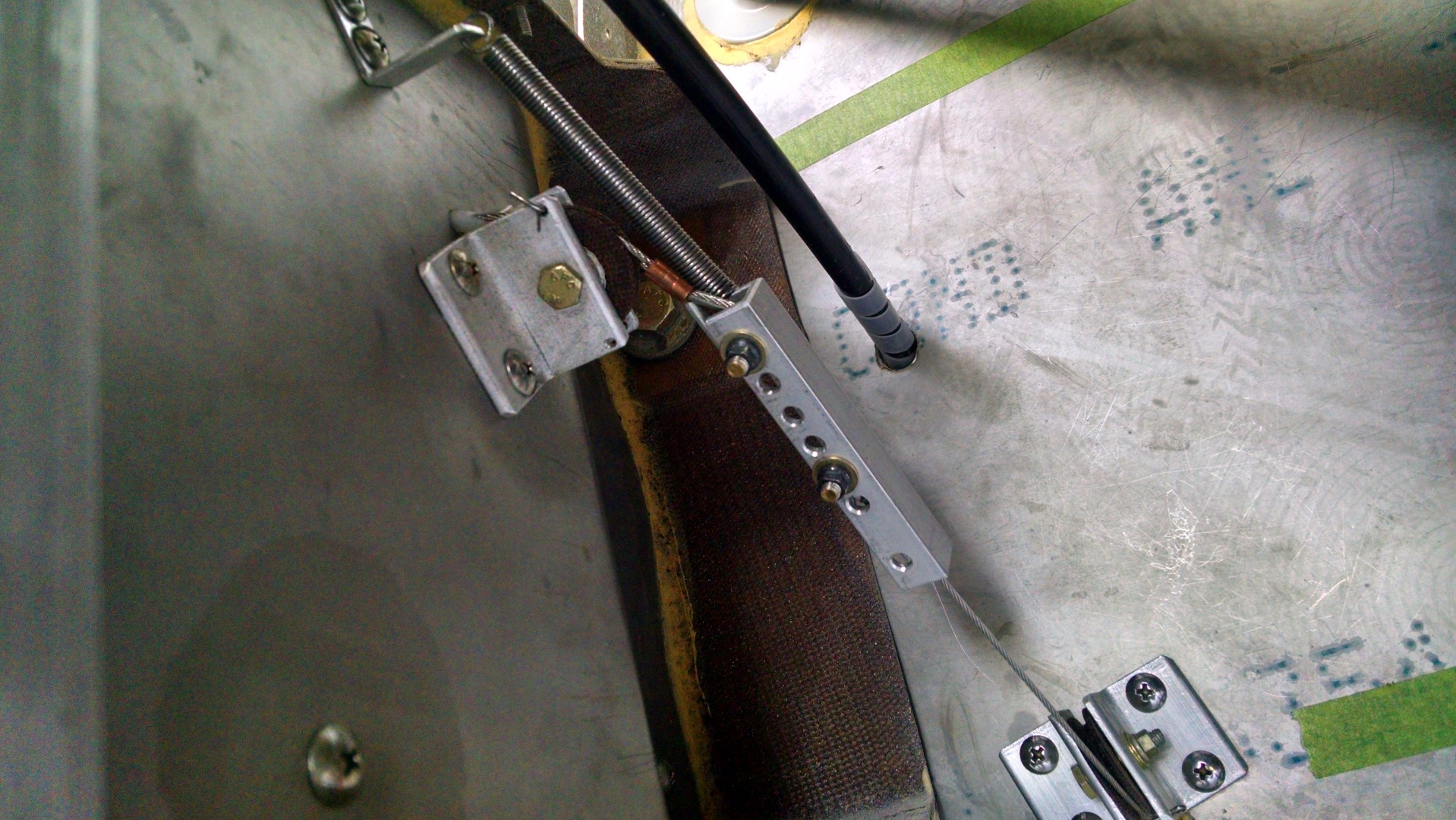
Here’s the pilot-side rudder cable coupler (looking from below and slightly aft) with the return spring mounted.

2015-01-21 1206 IMG_20150121_120618833_HDR (Large)

And here is a view looking from below and inboard.

2015-01-21 1206 IMG_20150121_120629507 (Large)

And finally, the co-pilot side.

2015-01-21 1059 IMG_20150121_105945872_HDR (Large)

9.7 Fuel Shutoff Valves

This entry is part 5 of 18 in the series 09 - Fuel System

The fuel system is rather simple.  There are the two strake tanks (out near the wings) which each feed into a center “sump” tank which in turn has a single line going to the engine.

Unlike most other aircraft which have valves that allow you to select which tank you are supplying the engine with, the Velocity only has a single shutoff valve between the sump tank and the engine. And it’s not controllable from the pilot’s seat.  So basically there is no “fuel management” in a Velocity other than to not run out (of fuel).

To accomplish that, I’ve got fuel gauges that will need to be calibrated. To do that, you add fuel, 5 gallons at a time to one of the fuel tanks while configuring the engine monitor until the tank is full. The problem is that when you add fuel to one tank it goes into the sump and then flows into the other tank. Now there is a method to accomplish this which involves disconnecting the strake-to-sump fuel line and attaching a flexible line to the strake with a shutoff valve.  Then you add the fuel in 5-gallon increments until full and calibrate the fuel gauge.

Then you drain that fuel into 5-gallon jugs and repeat on the other tank.

But I had an idea. Put shutoff valves between the strake and sump tanks. This will allow me you calibrate the fuel gauges and it would also let me isolate the main fuel tanks if I ever need to do maintenance.

Here’s the pilot side strake-to-sump fuel line.

2015-01-20 0948 IMG_20150120_094807767 (Large)

And here’s the valve that I plumbed in.

2015-01-20 1746 IMG_20150120_174622587 (Large)

Still not sure about the whole thing. It adds a bunch of connections (each one being a potential leak) and the only time that I’ll probably ever use it is when I calibrate the fuel gauges.

13.3.3 / 13.5.3 Trim & Landing Light Test

This entry is part 51 of 67 in the series 13 - Electrical / Instruments

The canard is now installed and all the wires have been run.

2015-01-21 1201 IMG_20150121_120138393 (Large)

The TCW Trim Controller works like a champ.  When I first tested it, I thought there was a problem since it would only run for about three seconds and then stop.  But then I remembered that there is a “trim runaway” protection feature which prevents a stuck switch from resulting in the trim being run all the way.  So you just have to re-activate the switch if you ever need more trim.  There’s also a reverse trim function that also works perfectly.

There is also a high and low speed trim function so that when you’re flying slow (like in the pattern) the trim motor runs at a higher speed than it does when you’re flying fast.  I haven’t tested that function yet.

I also powered up the landing lights.

2015-01-19 1059 IMG_20150119_105915478 (Large)

14.0 – Punchlist

This entry is part 20 of 38 in the series 14 - Final Assembly / FInishing

Making progress on Malcolm’s punchlist.

Fewer items than there were before.

2015-01-18 IMG_20141217_083024900 (Large) 2015-01-18 IMG_20141217_083036202 (Large)

Some of the items are pretty much done but since they aren’t “finished” I haven’t marked them off yet.  For example, the Vortalons, sparrow strainer and oil-door rework is pretty much complete.

Right now we’re working on the toe-in adjustment (AKA, wheel alignment) and it’s turning out to be very difficult.  We just can’t get a consistent setting.  Depending on the order the bolts are tightened, the measurement changes significantly.  It’s possible that the axles may have to come off and the gear leg gets re-worked. 🙁

13.2.1 Instrument Panel – Final Install

This entry is part 50 of 67 in the series 13 - Electrical / Instruments

With the new battery installed, Audio Panel moved, and GPS installed, it’s time to reassemble the instrument panel for (I hope) the last time.  During this install, I’ll be using locking hardware and securing wires.

Once everything was back together it was time to fire up the electronics for the first time in quite a while.

I was so very happy that everything powered up properly!

2015-01-18 IMG_20150118_154232895_HDR (Large)

Since the glareshield is now installed, I can test the panel lights as well.

2015-01-18 IMG_20150118_154244987_HDR (Large)

And since the wings were now on and wired, I was able to test the Nav and strobe lights.

2015-01-19 1059 IMG_20150119_105945849 (Large)

Next, I’ll install the canard and connect the landing lights, trim motor and heater fan and test those.  I’ve also got to find a headset and see if the radios work.


13.6.1 Battery Hold-Down

This entry is part 49 of 67 in the series 13 - Electrical / Instruments

The battery that I have been using is a used one which came out of another airplane.  The dimensions are pretty standard so I used it as a template when I was building the battery tray.

It was a standard flooded cell, lead/acid battery.  And the cover plate was also the hold down strap.

But I decided on a sealed battery.  Which means that I don’t have to worry about putting in an overflow drain.  But the new battery doesn’t have an intergated hold-down.  So it’s fabrication time again.

The battery has these two little… tabs sticking up.  I could have just gone over top of those but I was worried that pressing down on those would cause trouble in the future. So instead of using flat plate, I used I picked up some 3/4″ square stock and cut it to length and notched the square stock. Then drilled two holes for the rods.

2015-01-18 IMG_20150118_092653974 (Large)

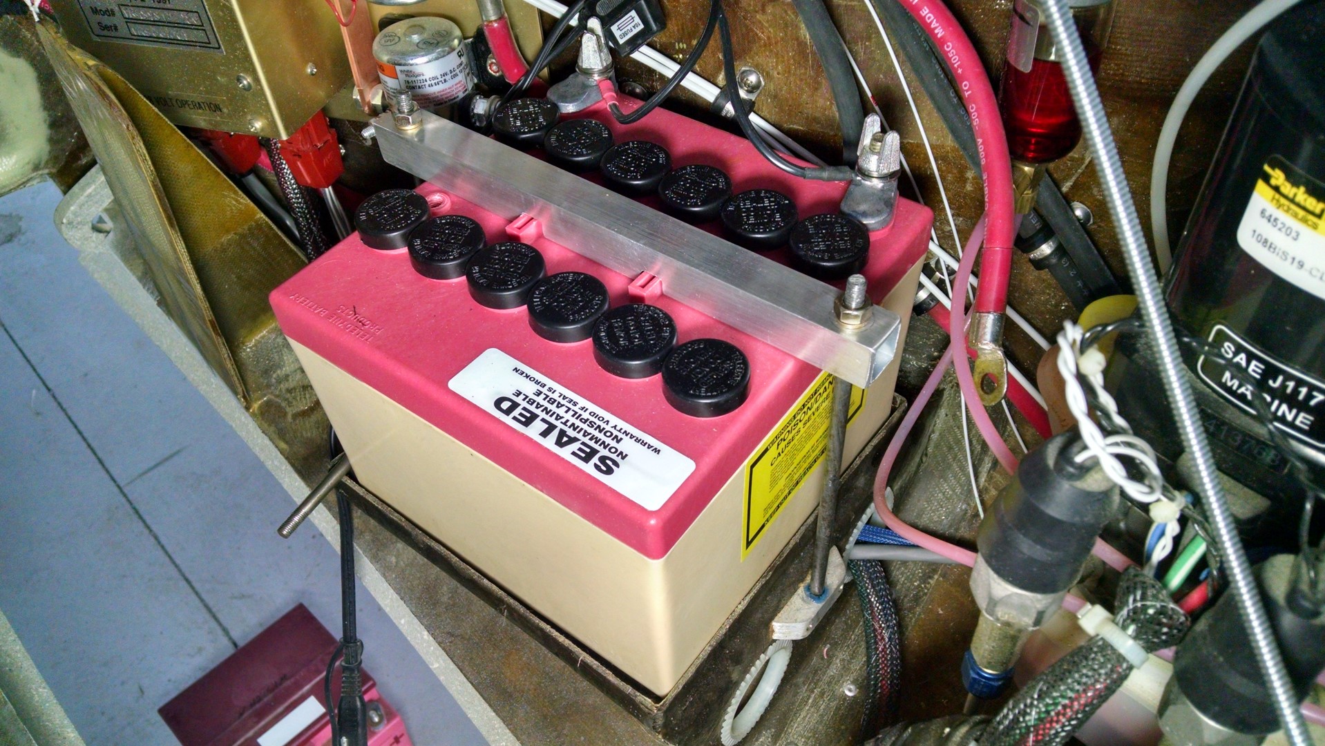
Here’s the hold-down bar on the new battery.

2015-01-18 IMG_20150118_093345829_HDR (Large)


13.7.4 Audio Panel Relocation

This entry is part 47 of 67 in the series 13 - Electrical / Instruments

I got the old mounting bracket and relocated the audio panel.

Before:

2014-08-26 IMG_20140826_170407171 (Large)

After:

2015-01-17 IMG_20150117_103302083_HDR (Large)

I got the battery yesterday but had to make a change in the instrument panel today so I won’t get all the electrical hooked up and test to verify clearance from the pitch trim spring until (hopefully) tomorrow.


13.1.8 GPS Antenna Shelf

This entry is part 46 of 67 in the series 13 - Electrical / Instruments

Now that I (finally) have an IFR capable GPS, I need an antenna.  I could have purchased one from Grand Rapids for $550, but I decided to check with the manufacture of the antenna they sell.  Sensor Systems sold me the same antenna for about $425.  Sweet!

Usually the antenna is mounted top of the fuselage.  On aluminum aircraft, you have to put it outside otherwise the metal blocks the signal.  That’s not an issue with a composite aircraft.

Most Velocity builders put the antenna on the canard under the cover known as the “doghouse”.  Other builders create a shelf under the doghouse.

Me and Malcolm went back and forth on the best approach.  Under the doghouse and you have lift up the doghouse and reach in to disconnect the antenna before removing the doghouse completely. On the canard and it’s one more thing competing for space in a very busy area with things that move (trim motor and autopilot pitch servo). And it’s got to be elevated to allow for the antenna cable.

In the end I decided to put it under the doghouse.

So Malcolm did what Malcolm does best: Create things out of resin and fiberglass.

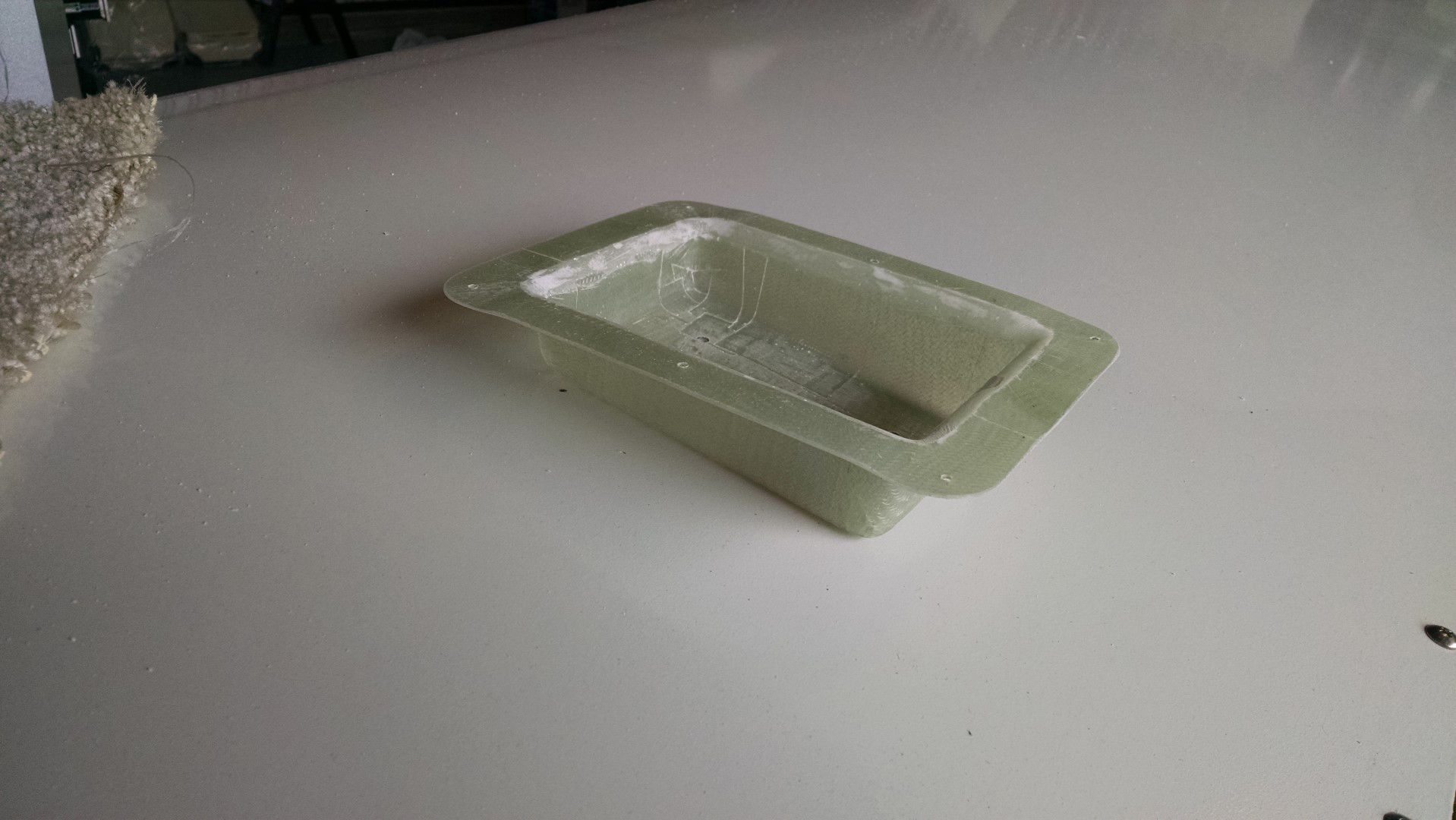
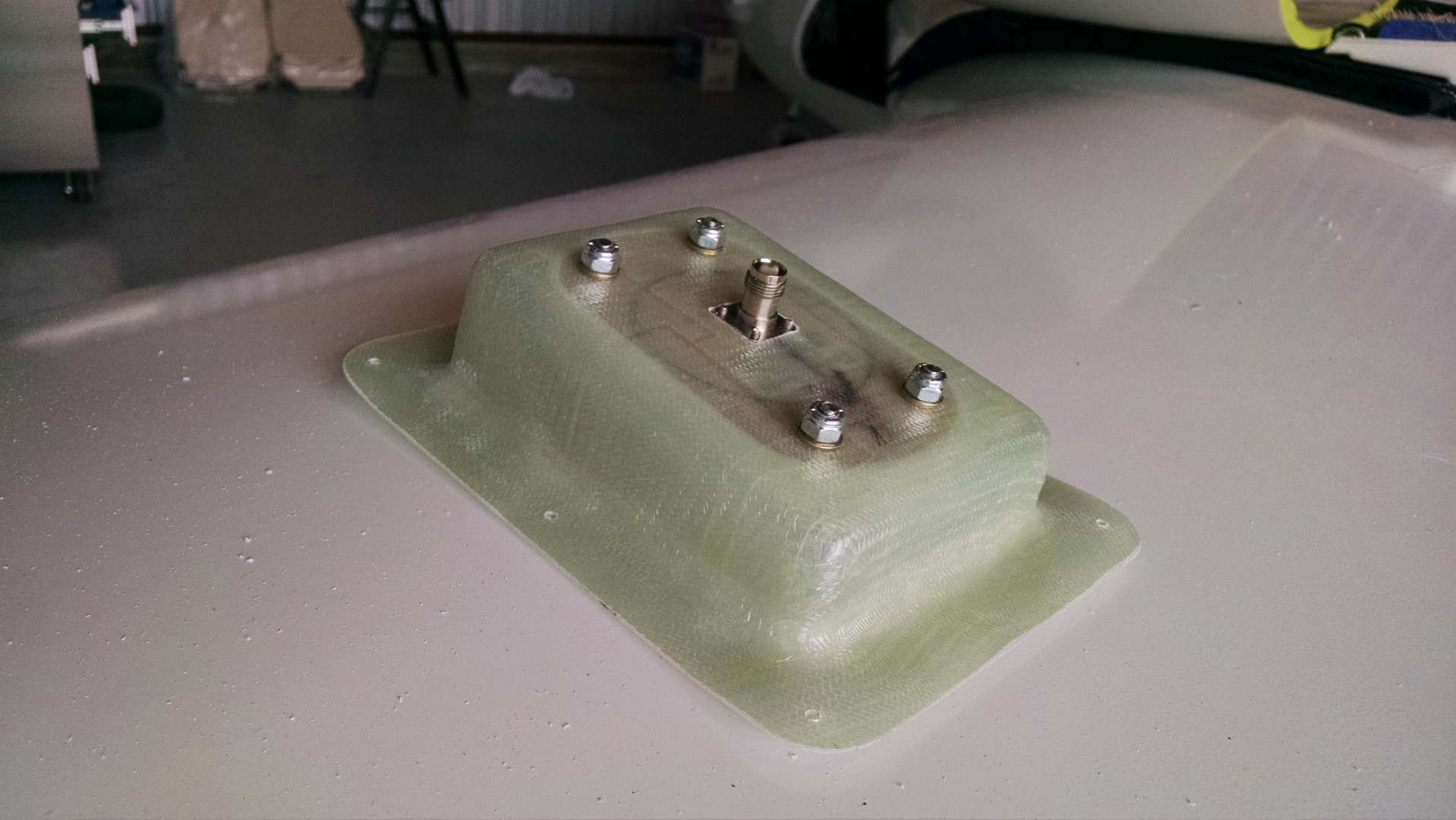
Here’s the GPS Antenna Shelf.

2015-01-16 IMG_20150116_092301942 (Large)

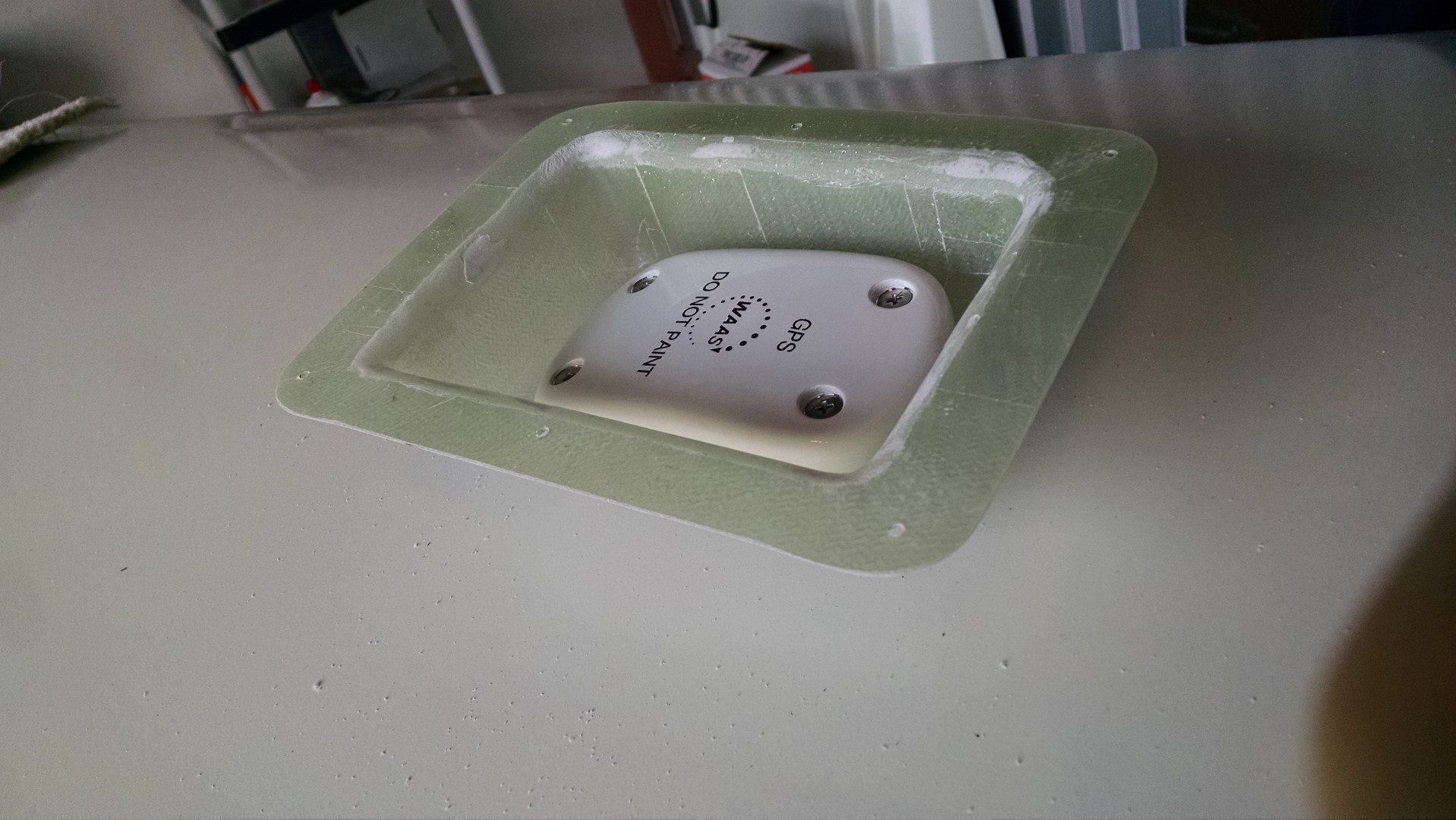
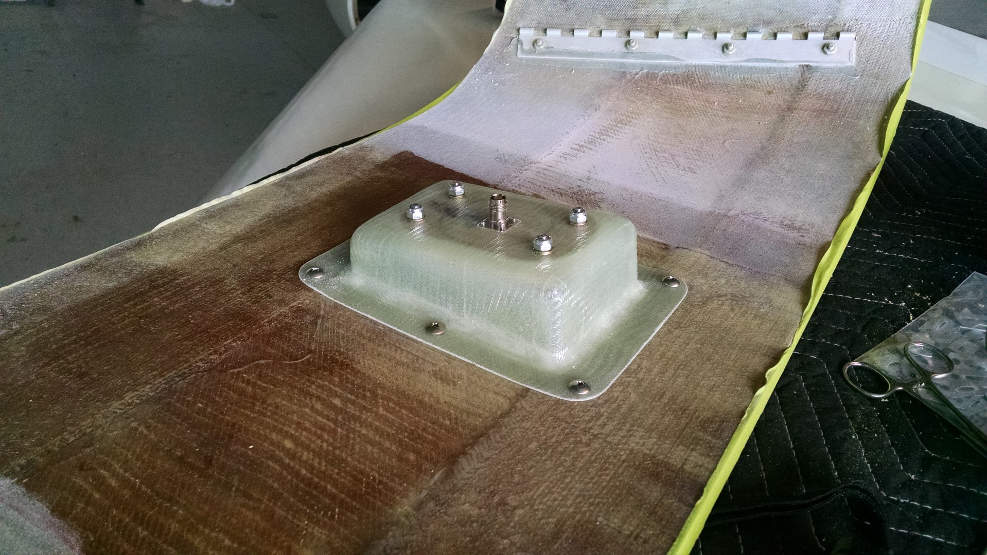
With the antenna installed

2015-01-16 IMG_20150116_092854521 (Large)2015-01-16 IMG_20150116_092832475 (Large)

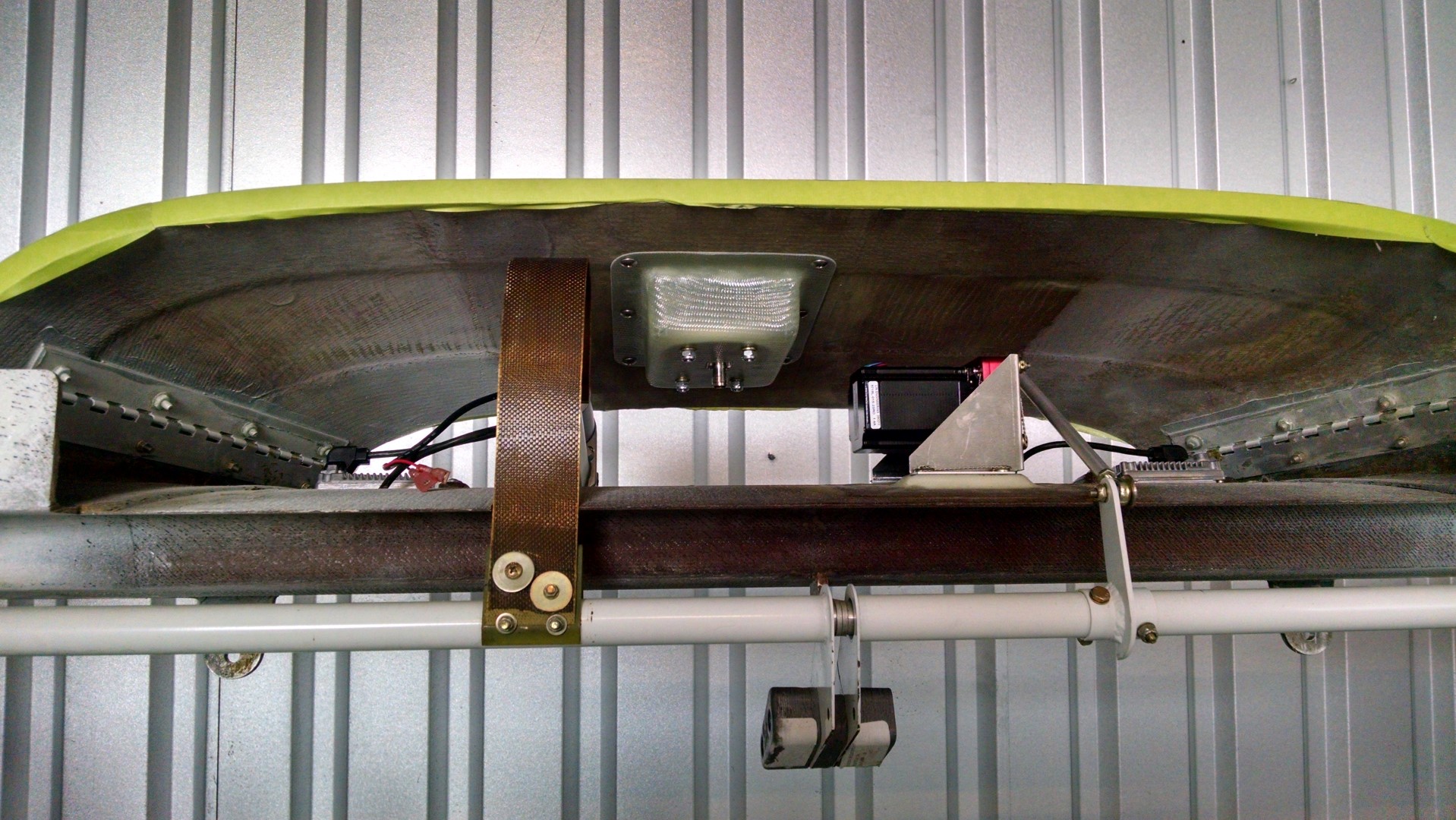
Attached to the underside of the doghouse.

2015-01-16 IMG_20150116_093808645 (Large)

With the doghouse installed on the canard.

2015-01-16 IMG_20150116_093910110_HDR (Large)

13.0 Wire Routing (Remediation)

This entry is part 48 of 67 in the series 13 - Electrical / Instruments

I finished the re-securing of the smaller wire bundles.

Here’s the left main gear leg with the wire bundle for the landing gear position sensors.

2015-01-14 IMG_20150114_153735081 (Large)2015-01-14 IMG_20150114_153728438 (Large)2015-01-14 IMG_20150114_153744946 (Large)

You’ll notice quite a few of those crappy, nylon wire mounts were loose. Not only could that damage a wire which would indicate an unsafe landing gear but it could also affect the mechanism itself and prevent the landing gear from locking in place.

So I removed all of those pads and replaced them with the new style. Which are not epoxied in place with structural adhesive.

2015-01-15 IMG_20150115_083238478 (Large)

These puppies aren’t going anywhere!

13.0 Wire routing

This entry is part 45 of 67 in the series 13 - Electrical / Instruments

One of the tasks with the electrical system is securing the wires. Larger wires like the main power distribution wires and large wire bundles are secured by Adel clamps.  2013-12-13 IMG_20131213_101703_841a

It’s also possible to use Adel clamps for smaller wire bundles. This is the autopilot roll servo wire harness.

2014-08-01 IMG_20140801_080749709 (Large)

But in some places, Adel clamps are difficult to use if there’s limited space/access since they have to be screwed in and they’re a bit overkill for small wire runs.

One of the places they won’t work is on the gear legs.  I don’t want to do anything that could affect the integrity of the gear leg like drilling a hole in it.

So I picked up a bag of plastic wire tie mounts with self adhesive foam backing at Oshkosh.

$_12

Because the gear leg is not smooth, I made some “pads” with epoxy/cabo covered by some small 1″x1″ pieces of wood covered with duct tape.  Once the epoxy cured, I popped off the wood and had a perfectly flat surface to attach the foam mount to.

Here’s the gear leg with the wire mount.

2013-11-08 IMG_20131108_175421_131 (Large)

It held pretty good… for a while.  Then it came loose.  The amount of pull on the wires when the gear retracts is just more than the foam adhesive can handle. I even found some other places that didn’t have much stress on them which came loose as well.  And since it’s made out of nylon, finding a glue that can adhere to it would be a pain. There are probably some of these available that have NASA quality adhesive but they’re also probably $5 each.

So fellow builder Erik Franks mentioned these guys.

2015-01-10 IMG_20150110_085310377 (Large)2015-01-10 IMG_20150110_085317435 (Large)

Since they’re made out of aluminum, Resin Research epoxy will bond to them very well (RR epoxy is real good for bonding to aluminum!).  They’re small, light and have a lower profile than the plastic mounts.

So next week when I’m down in Sebastian, I’ll swap out the old plastic POS mounts with the new ones.