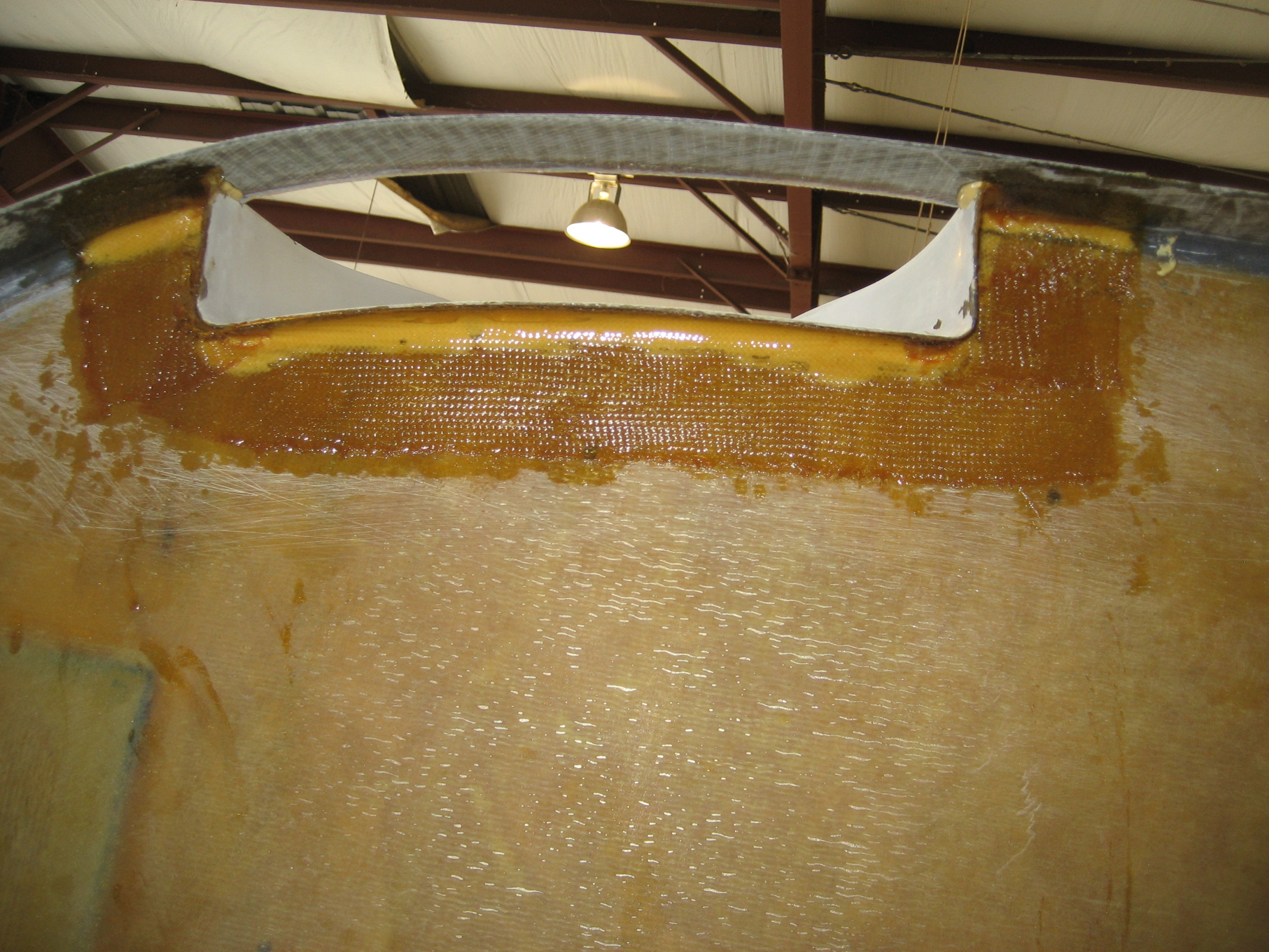
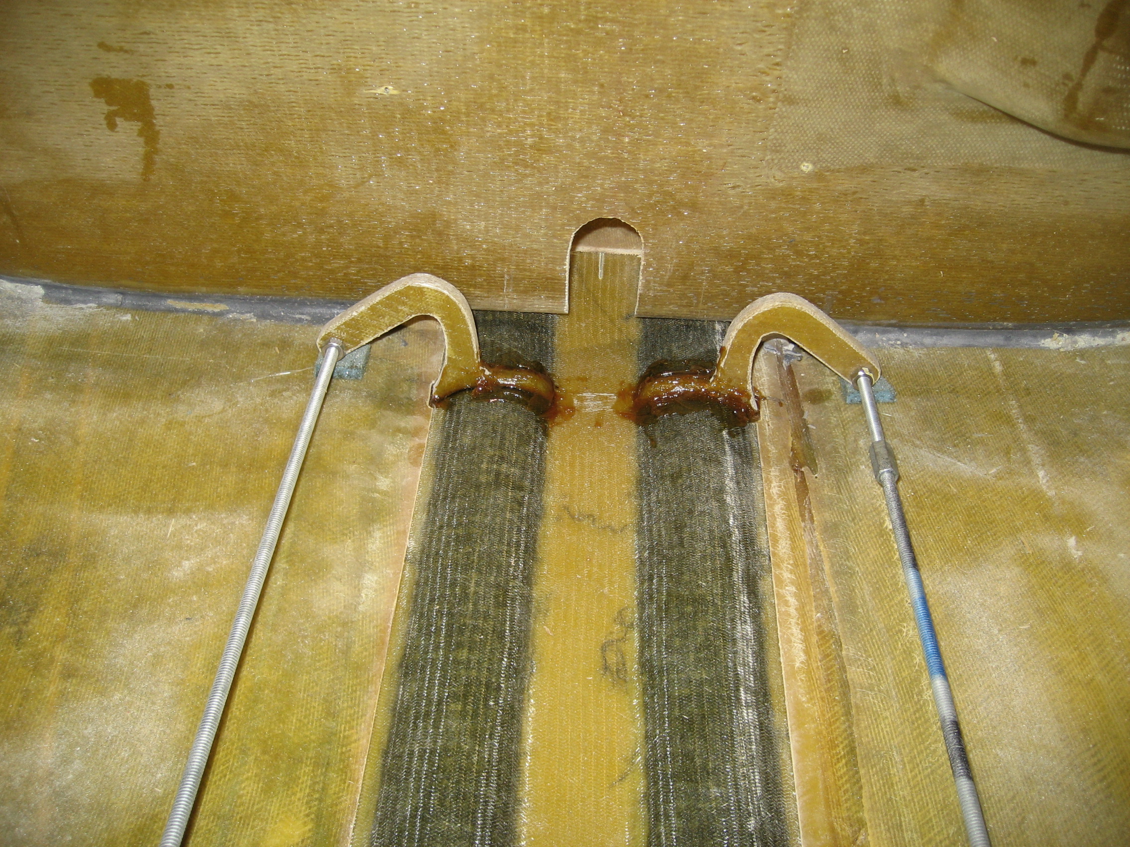
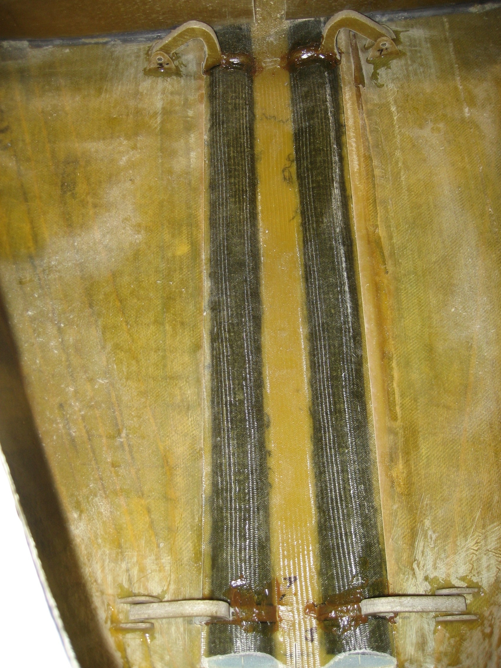
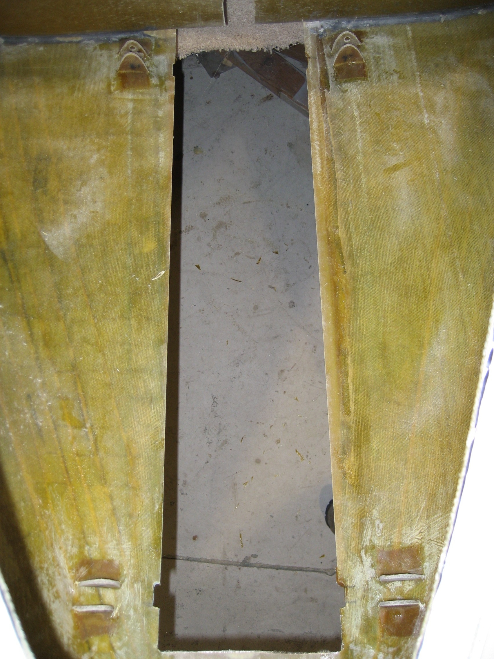
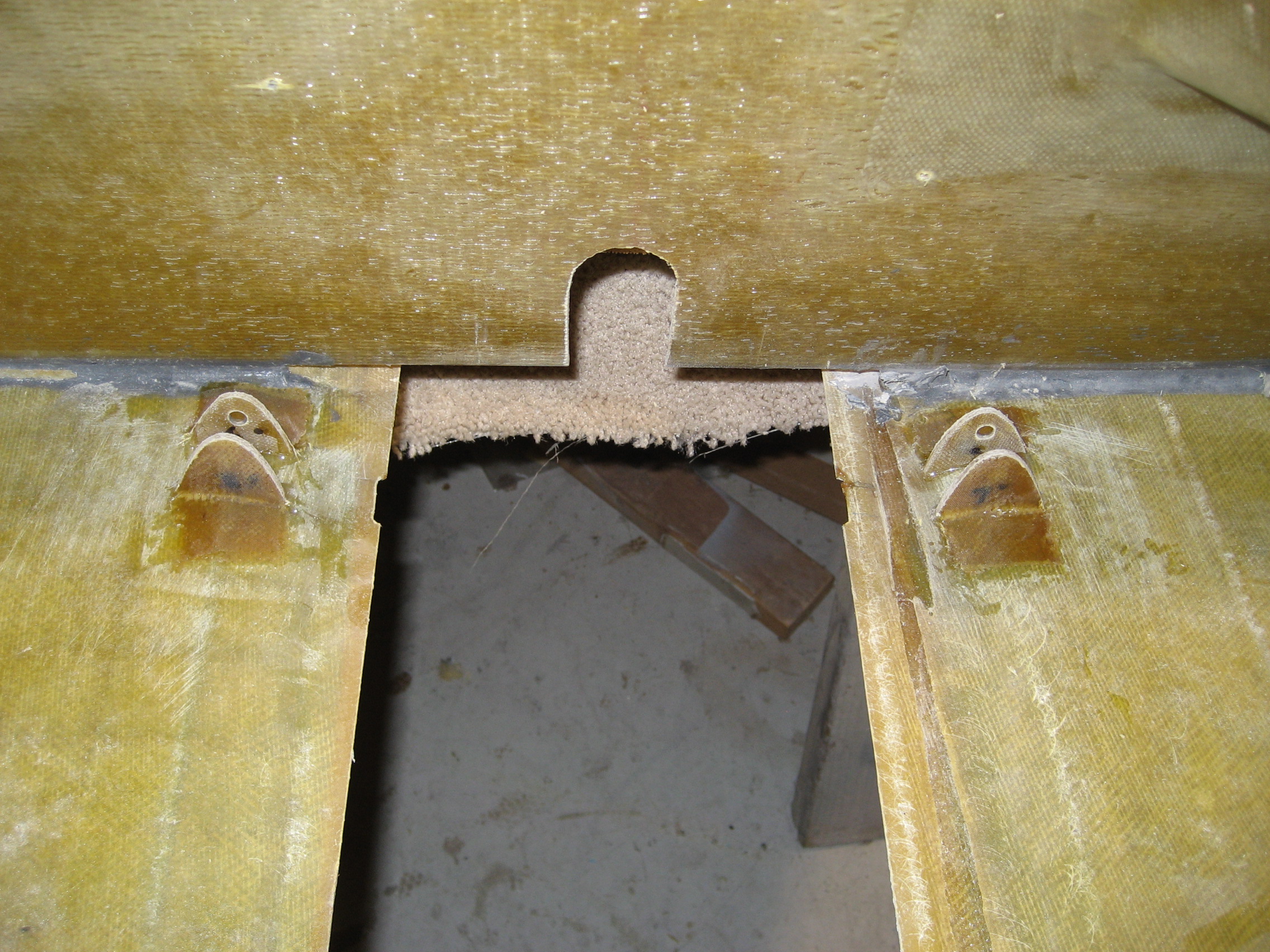
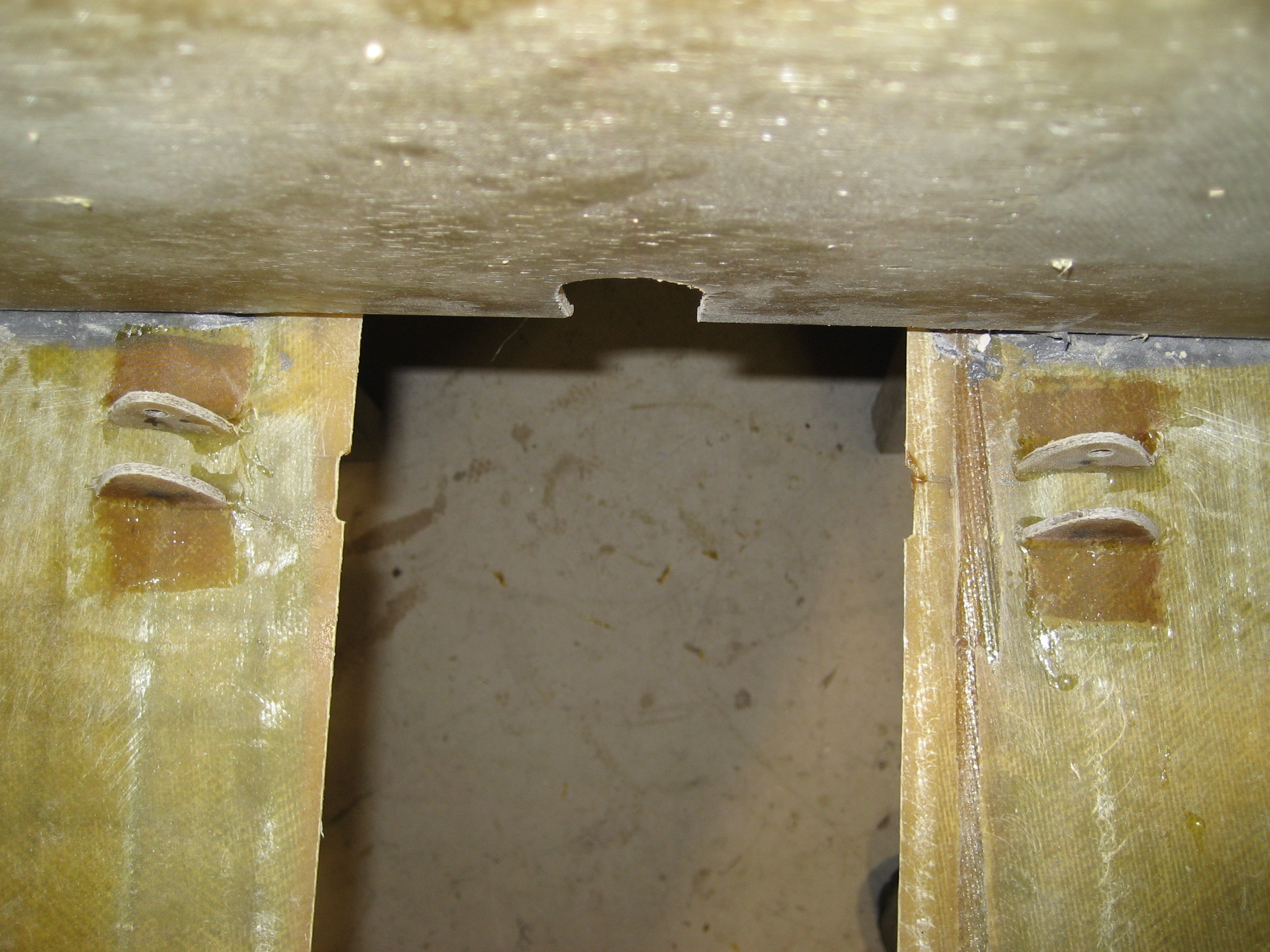
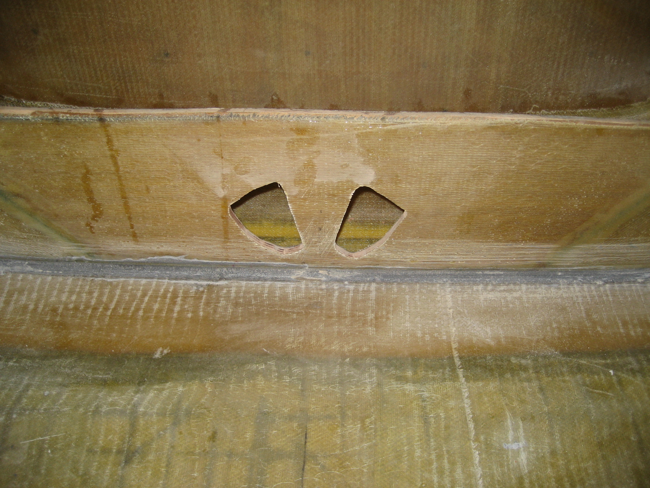
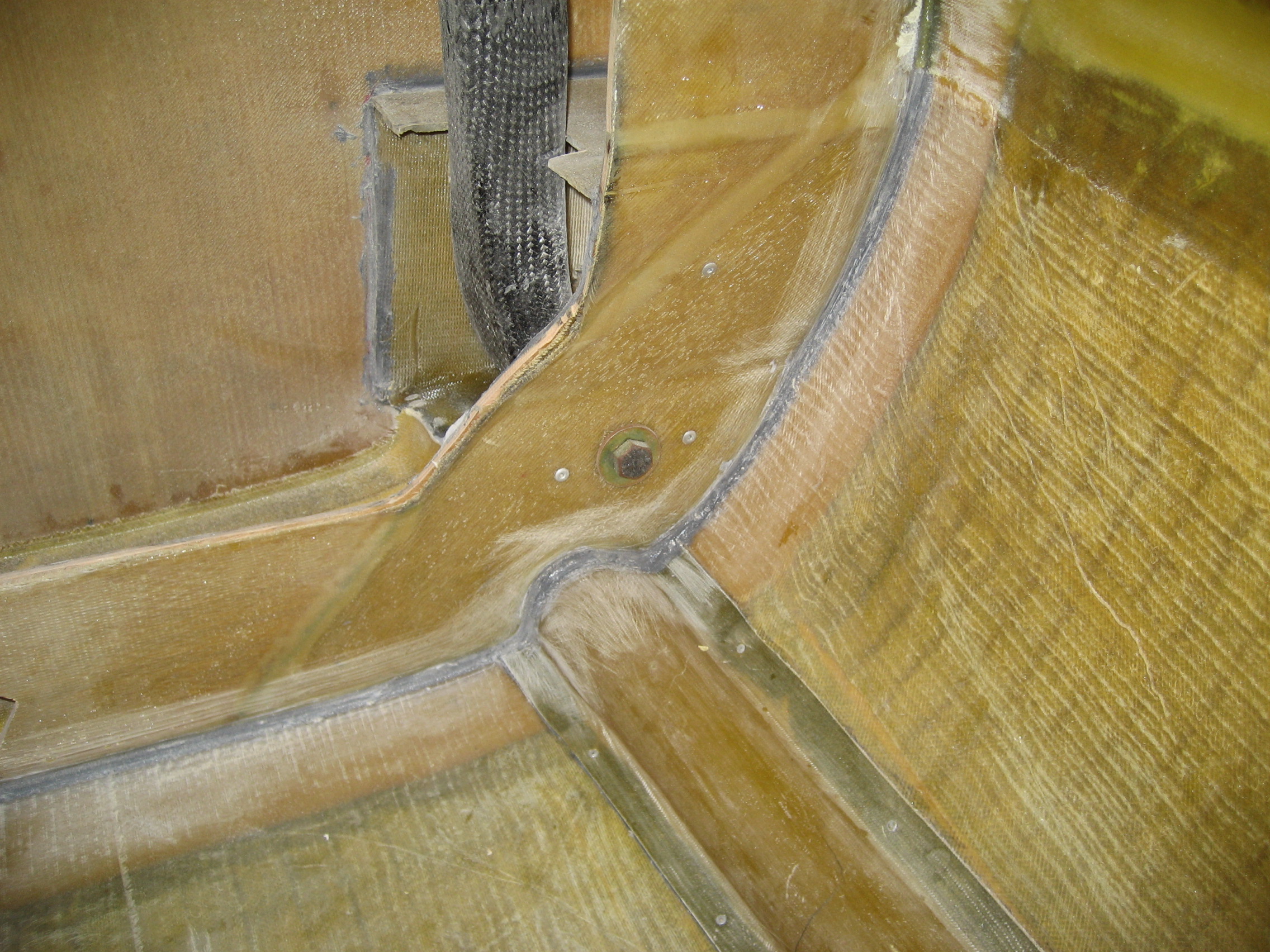
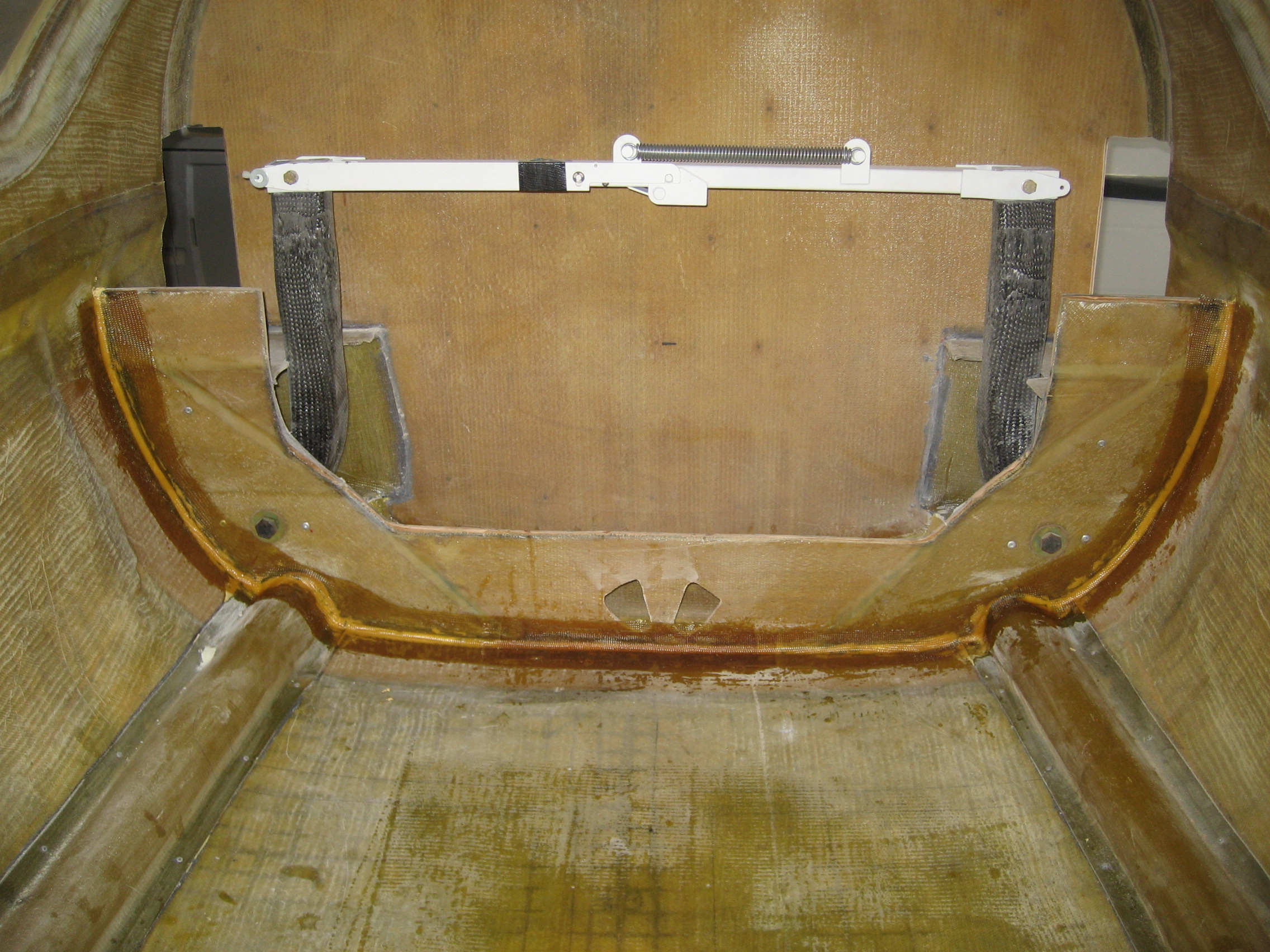
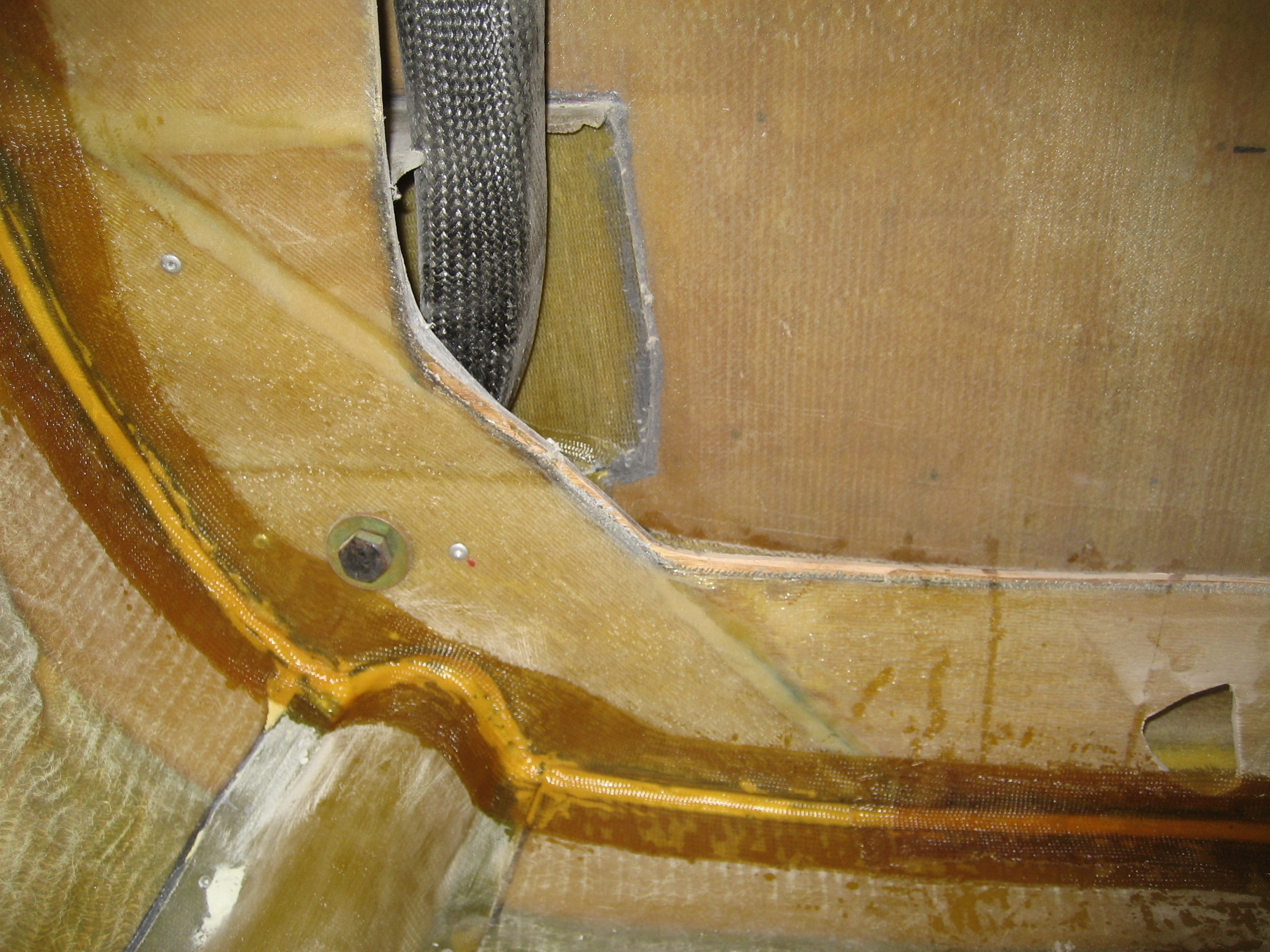
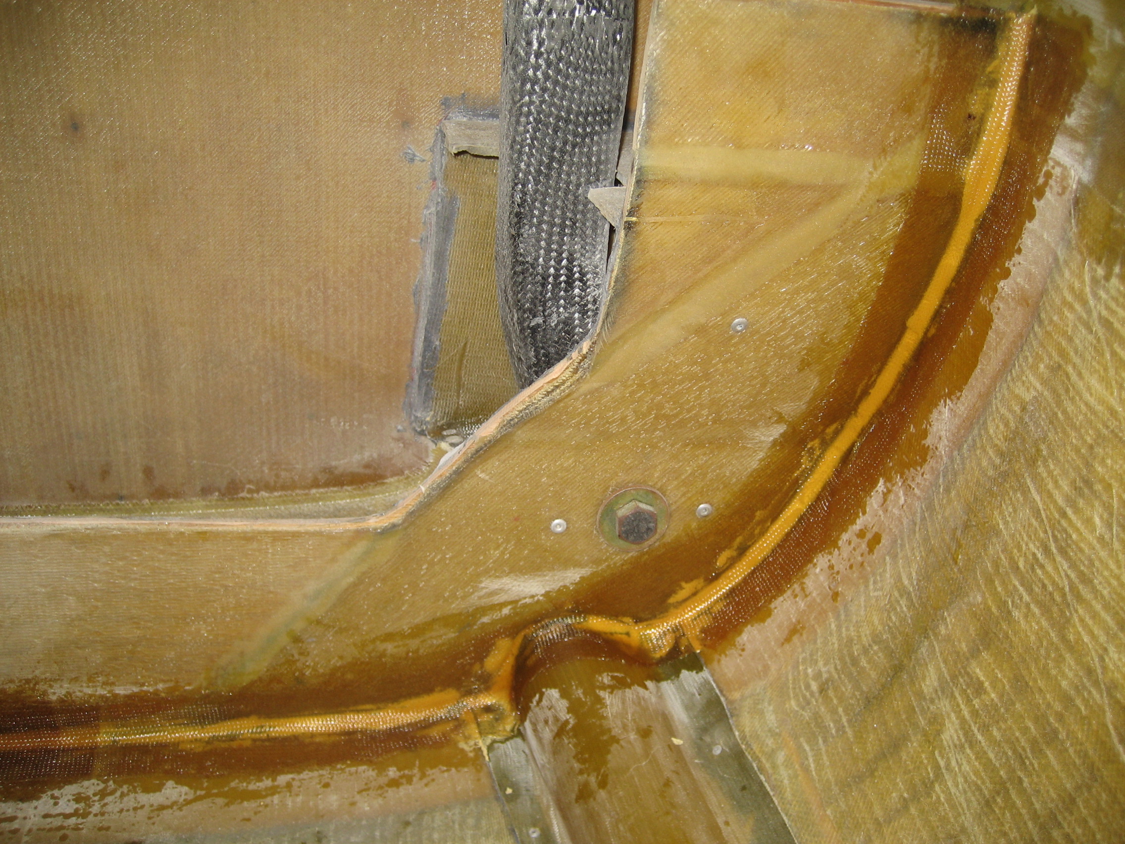
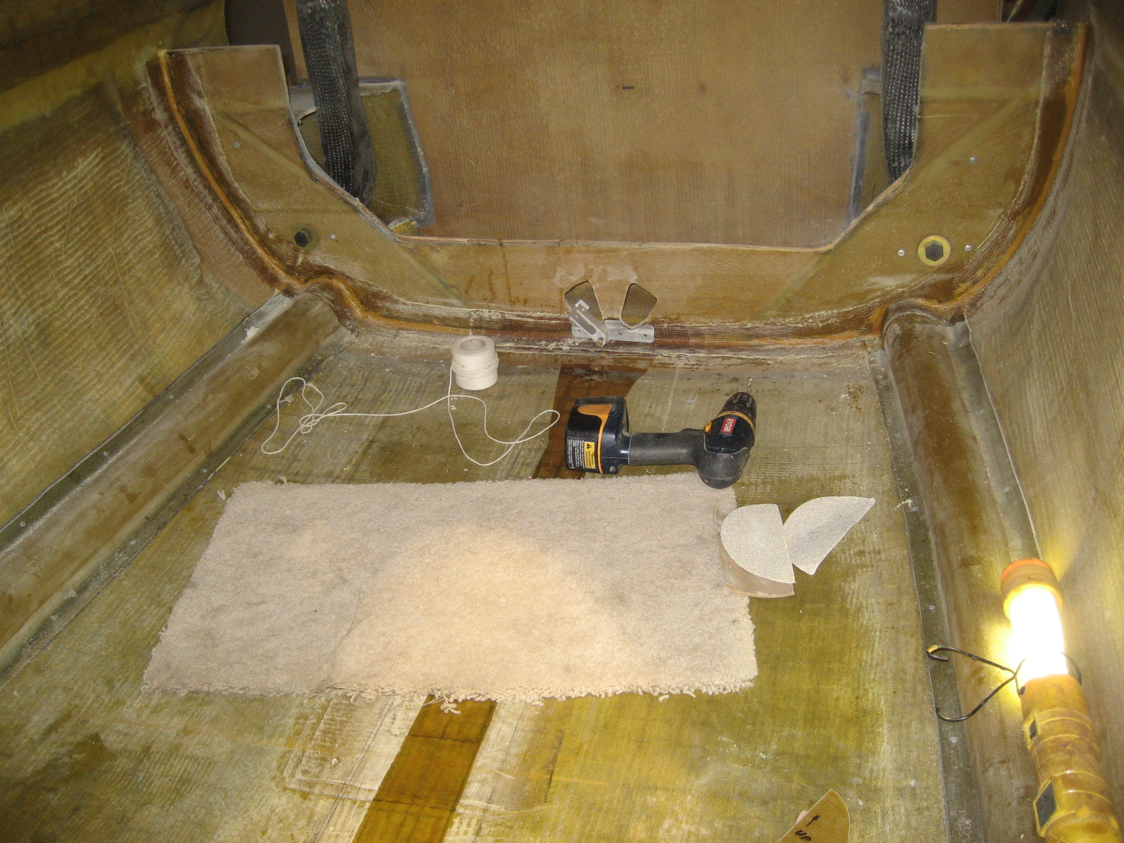
The last task for the day was to create a rectangular opening just forward of the firewall on each side of the fuselage for the main spar. The spar is the primary mounting point for the main wings.
Category Archives: 2008
11.1.5 Premolded NACA Duct Installation
7.6.3 / 7.8.1 Install Landing Gear Hydraulic Cylinders
The hydraulic cylinders which actuate the nose and main landing gear are attached to the floor of the fuselage in positions called out in the manual. The holes for the mounts run through the floor and countersunk, flathead screws are used from the outside.
I also fabricated the two hydraulic lines that run between the hydraulic cylinders.
Nose gear cylinder
Main gear cylinder
3.4.6 Elevator Hinge Arm Installation
Now it’s time to mount the hinge arm to the canard.
First, the location of the L-shaped hinge arms are identified and slots are cut into the fiberglass at the rear of the canard. Then the foam is removed to create a pocket for the hinge arm.
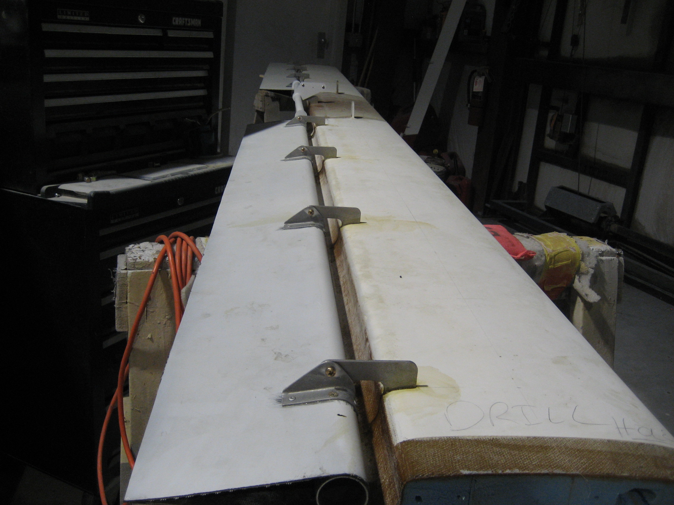
Next the position of the elevator (relative to the canard) has to be established. This is done by laying the canard on its back and using straight beams to establish the bottom of the canard. Then the elevators are put into position and clamped in place with the hinge arms in their pockets. To insure alignment of the two elevators, the elevator torque tube is temporarily installed which connects the two elevators.
Here’s the canard (it’s upside down so you’re looking at the bottom) with the two elevators in position. The elevators are held in the approximate position with aluminum I-beams, weights and clamps while we tweak the alignment. Lots of straight edges and string is used to make certain everything is aligned.
Once we’re happy that everything is just right, an epoxy/cabo mix is injected into the pockets where the hinge arm are.
7.1 Nose Gear Door Installation
The Nose Gear Doors are provided as a single assembly. They will eventually be cut into two separate doors.
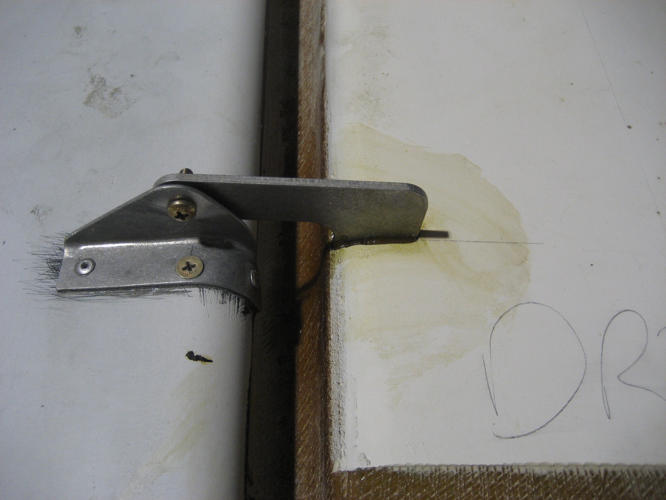
Earlier, I laminated many pieces of fiberglass to create the stock that the hinges would be made from. These hinges are basically a “J-hinge” which are similar to the hinge arms used in doors and trunks of cars. They allow a form-fitting piece to swing away from the body without rubbing against it.
To install the doors, first they are bonded to the opening with auto-body filler (Bondo) to temporarily but firmly hold them in position while the hinges are positioned and permanently bonded into place.
Nose gear doors held in place with Bondo.
Next, the hinges are aligned with lengths of all-thread and then the hinges are bonded to the gear door with an epoxy/cabo mix.
Once the epoxy cures, the all thread is removed that then eight tabs (two for each hinge arm) that I cut out of fiberglass layups are used to create the fuselage side of the hinges are bonded to the fuselage. These tabs are custom fitted to the fuselage. I numbered them to keep track of where they go and put a dot on the forward faces side. Once these cure, then the nose gear door can be removed and cut into two pieces, and the hinge arms and tabs can receive fiberglass layups to make them permanent.
Nose gear door (still one piece) with the tabs glued in position.
Close up of the rear portion of the door, hinge arms and tabs.
7.1 Nose Gear Door Installation
Once the door hinge tabs had set up, I cut the nose gear door in half. A rather difficult task considering that I was doing it in a somewhat upside down position. But once they were in half, they can be removed and then reinforcement layups are put over the hinge arms and over the hinge tabs to the fuselage.
This the inside of the nose area with the doors removed and the layups on the outside of the hinge tabs.
Closeup of the rear tabs. I have to drill through the layups that cover the holes in the tabs.
The (now two) nose gear doors with the layups over the hinge arms.
4.2.3 Main Gear Bulkhead
The main gear bulkhead is a structural component which the main landing gear attaches to. This bulkhead gets reinforced with two layers of BID.
Inside of the cabin looking aft. Just in front of the main landing gear is the Main Gear Bulkhead. The gray that goes halfway around the bottom is structural epoxy that holds the bulkhead in place for now. At the bottom on either side are two chases (or channels) that will be used to run electrical cables to the engine compartment. The two cutouts in the center of the bulkhead are where the cables that retract the landing gear go through the bulkhead.

Close up of the left, center and right of the bulkhead.


The first task is to create a fillet with a “micro-slurry” (epoxy with microscopic bubbles called “micro-balloons” that thicken the epoxy). This rounds over the intersection where the bulkhead meets the fuselage. Then the two layers of BID are applied.
View of bulkhead after the micro-slurry fillet and BID layup. You’ll notice that instead of gray, the joint at the bulkhead is now yellowish. That’s the micro-slurry.

6.3.7 Keel Installation (prep)
6A.3.1 Rudder Pedal Assembly
7.6.1 Main Gear Pulley Installation
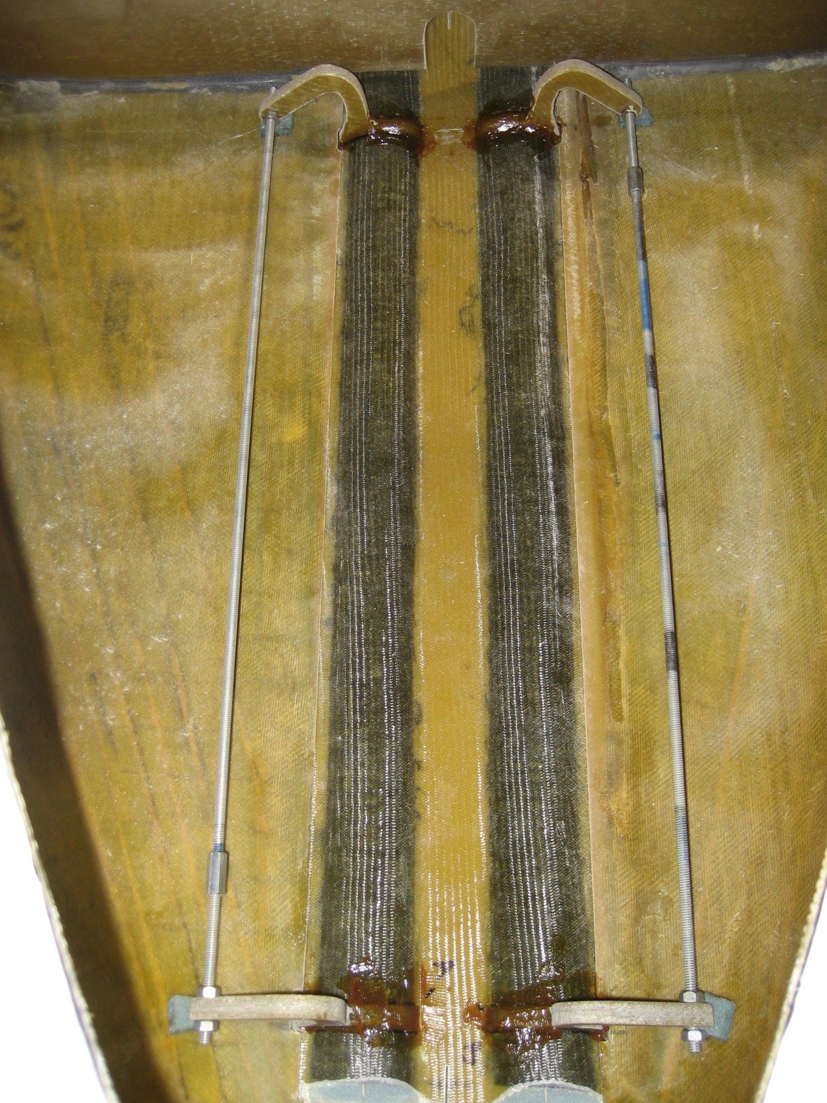
The main landing gear is retracted by the hydraulic cylinder pulling cables that attach to the top of the landing gear. This cable has to pass through a pair of pulleys at the center of the main gear bulkhead.
The mounting hardware is temporarily held in place and string is used to insure the path of the cables does not rub or bind between where the cylinder is and the top of the gear leg. Once the location has been determined, holes are drilled through the bulkhead.
In this picture, the pulley has been removed.
The carpet really helps when you are kneeling.