7.8.4 – Landing Gear Electrical

This entry is part 12 of 39 in the series 07 - Landing Gear

I needed an easy task, so I decided to install the nose gear down switch.

The switch gets attached to the overcenter stop. I put some blue tape to make it easier to see the location I marked for the holes.

Then I removed the stop, drilled and taped the holes for 4-40 screws.

Reinstalled the stop and mounted the switch.

The up switch is going to require some creativity.

13.6 Electrical supply lines

This entry is part 31 of 67 in the series 13 - Electrical / Instruments

The way most Velocities are setup is with the master contactor (solenoid) and stater contactor located up front next to the battery. With the starter in the back, this means a fairly large gauge wire running back to the starter. It also means two slightly smaller gauge wires running from the alternators to the front.

Now because I’m running a 24v electrical system, I get to run smaller gauge wires than the 12v guys. So my starter wires will only be 4 AWG instead of 2 or 0 AWG.  This is nice because smaller is lighter, takes up less space and is easier to bend.

Copper wire is used throughout the aircraft. Aluminum is lighter, but there have been numerous documented problems with aluminum wire. One to my “go to” guys for supplies is Eric Jones at Perihelion Design. He’s supplied me with servo controllers, LED dimmers and switch guards. He also has this very interesting cable called CCA (Copper Clad Aluminum). It’s an aluminum cable that is covered in copper. So this wire is light weight (aluminum) and doesn’t have the problem associated with aluminum because it is covered in copper. It’s the best of both worlds. 🙂

Since I’m still in recovery mode, I decided to install one of the terminals on the cable just to see how it went. Normally, wire terminals are crimped on, but a good pair of crimpers for wire this big costs a lot of money and I only have about 6 to install. So it’s done in a McGyver fashion.

First I made a tool to hold the terminal and cable with a hole for a punch. Next I had to make a 5/16″ punch (an old screwdriver fit the bill nicely) Then with the cable and terminal held in position, I used the punch to “dimple” the terminal to “crimp” the cable. Then using a propane torch, I soldered the cable to the terminal. This will create a strong, permanent connection between the cable and the terminal.

Here you can see the dimple and how the solder has completely filled the end of the cable.

Finally, shrink tubing is used to cover the work.

I was able to find some yellow shrink tubing instead of the standard black.

12.4 EGT Probe Installation

This entry is part 35 of 50 in the series 12 - Engine / Propeller

Installing the EGT (Exhaust Gas Temperature) probes is pretty straightforward. Simply measure down 2″ – 8″ from the cylinder, drill an 1/8″ hole, insert the probe and tighten the clamp.

Well, except for the center cylinder. That exhaust tube has a slip joint. And because the entire exhaust system is relatively low-profile, the probe on that cylinder was going to be where the two pieces overlapped.

So first I marked and drilled the holes (I measured down 2″). Then I removed the exhaust assembly from both sides. On the center exhaust tube, I removed the inner part and drilled that hole out to 1/4″. Then deburred all the holes, re-assembled and re-mounted the exhaust system.

Then installed the probes for each cylinder.

13.8.2 Annunicator Panel

This entry is part 30 of 67 in the series 13 - Electrical / Instruments

On the instrument panel, there is a need for a warning system. Kind of like the “idiot lights” on a car instrument panel. The Grand Rapids and Vertical Power can display warnings and alerts, but sometimes it’s a bit difficult to identify the actual failure or notification.

Most builders put some lights on the panel and put a label under it.


Here’s an example for a Low Voltage and Starter Engaged warning.

But I wanted something a little bit nicer.


This is the “Master Warning Panel” in a Cessna 441.  Sweet!

I found some really nice Hi-Intensity, wide angle LEDs. I then designed the circuit board that the LEDs would be mounted to.
an-sch

But the one thing I kept coming back to was how to make (what I call) the mask. The thing with the lettering. My initial plan was to run some clear transparency stock through the the laser printer. But the black wasn’t opaque enough. But if I did two layers it was. but getting the two layers to align was very difficult. But that’s the only choice I had.

Then a friend told me that the shops that made trophies had this black stock that they hit with a laser and could make clear lettering. So I started calling around and I found one that could get the material and had the laser. After some back and forth on the dimensions and lettering, I had a “version 1” of the Annunicator Panel mask.

While I was working on the circuit design, I breadboarded the circuit. Here’s what it will look like.

Now I just have to build the housing, get the circuit board etched, solder all the components, and figure out how to mount the whole thing to the instrument panel. 🙂

12.4 Oil breather line

This entry is part 37 of 50 in the series 12 - Engine / Propeller

One of the benefits of a custom exhaust is the addition of a oil breather tube port. Normally, the breather tube is plumbed to the bottom of the fuselage. The downside to this is an oily belly and another (this time a big one) tube poking out the bottom of the fuselage.

The other alternative is an air/oil separator which dumps the oil back into the engine. The engine guys I’ve talked to HATE this. They say that oil tends to be acidic not that it’s not a good idea to plumb it back into the engine.

This solution will dump the oil into the exhaust where it will be burnt (supposedly) leaving only a trace film that will just wipe away.   We’ll see about that.

One of the challenges is how to connect the breather tube to the exhaust.

At Oshkosh I ran across some “High-Temp silicon hose”. I picked up a piece not knowing if it would even fit. To my surprise, not only is it the correct length, but it’s also the correct diameter.

Even though it’s “high-temp”, I decided to create a shield. The tube itself shouldn’t get too hot for this hose, but I decided to go belt and suspenders. So I got some of the leftover titanium and built a little shield.

2013-08-04 IMG_20130804_111539_825b

It might not even be necessary, but it can’t hurt.

13.8.2 Annunicator Panel

This entry is part 29 of 67 in the series 13 - Electrical / Instruments

Now that I’ve got the mask, it’s time to start making the frame. When I first started thinking about this idea, I wasn’t sure how I would make the frame that the mask and PCB attaches to. But as usual, Malcolm had the solution… Styrene. He uses it in a lot of his models.

In case you forgot. Malcolm’s tank.

I always think of Malcolm when I watch Flight of the Phoenix (the real one, not the remake).  The only difference is James Stewart would have been flying one fast plane out of that desert if Malcolm had built it.  🙂

So I picked up a 12″x”6″x .06″ sheet of styrene and cement. I cut three 1″ wide strips. Two of the strips I cut down to the same length as the mask. These would become the top and bottom of the frame. The remaining strip I cut into nine half-inch long pieces.

I marked the position of the spacers on one of the long pieces and then glued the end spacer on.

To insure proper spacing and to keep the spacers at 90 degrees to the bottom, I used a scrap of 1×1 aluminum with a shim to get the spacing just right.

Now all the spacers are attached to the bottom.

I flipped the assembly on its back and then cemented the top on.

Finished product… kind of. I still have to create a flange for the PCB mount and the instrument panel mount. And I have to paint it black. But I’m getting there.

13.8.2 Annunicator Panel

This entry is part 28 of 67 in the series 13 - Electrical / Instruments

Once the basic frame was done, I had to add a flange to hold the mask. I used some 3/16″ styrene angle stock and created a recess to hold the mask.

Which fits in just about perfectly!

Then I reinforced the flange with a plate of .60″ sheet.

Next I created the mounting pads for the printed circuit board.

I was going to simply glue in the mask and leave it at that. But I wasn’t sure how the gap between the mask and flange was going to look. And there would be no easy way to replace the mask. So I decided to make a faceplate to cover it.

Here’s the frame with the mask and faceplate installed.

And with the PCB attached.


Then I painted the frame and faceplate flat black.

Now it’s time to start assembling the components onto the PCB.

Here are the HiFlux, 90 degree LEDs installed.

The connectors, resistors, diodes and transistors.

Finished Annunicator Panel (AKA, Master Warning Panel).

With the Fuel Pump (Amber), Pilot Door Unsafe and Parking Brake (Red) indicators illuminated.


12.2.4 Oil Pressure Sensor (remediation)

This entry is part 36 of 50 in the series 12 - Engine / Propeller

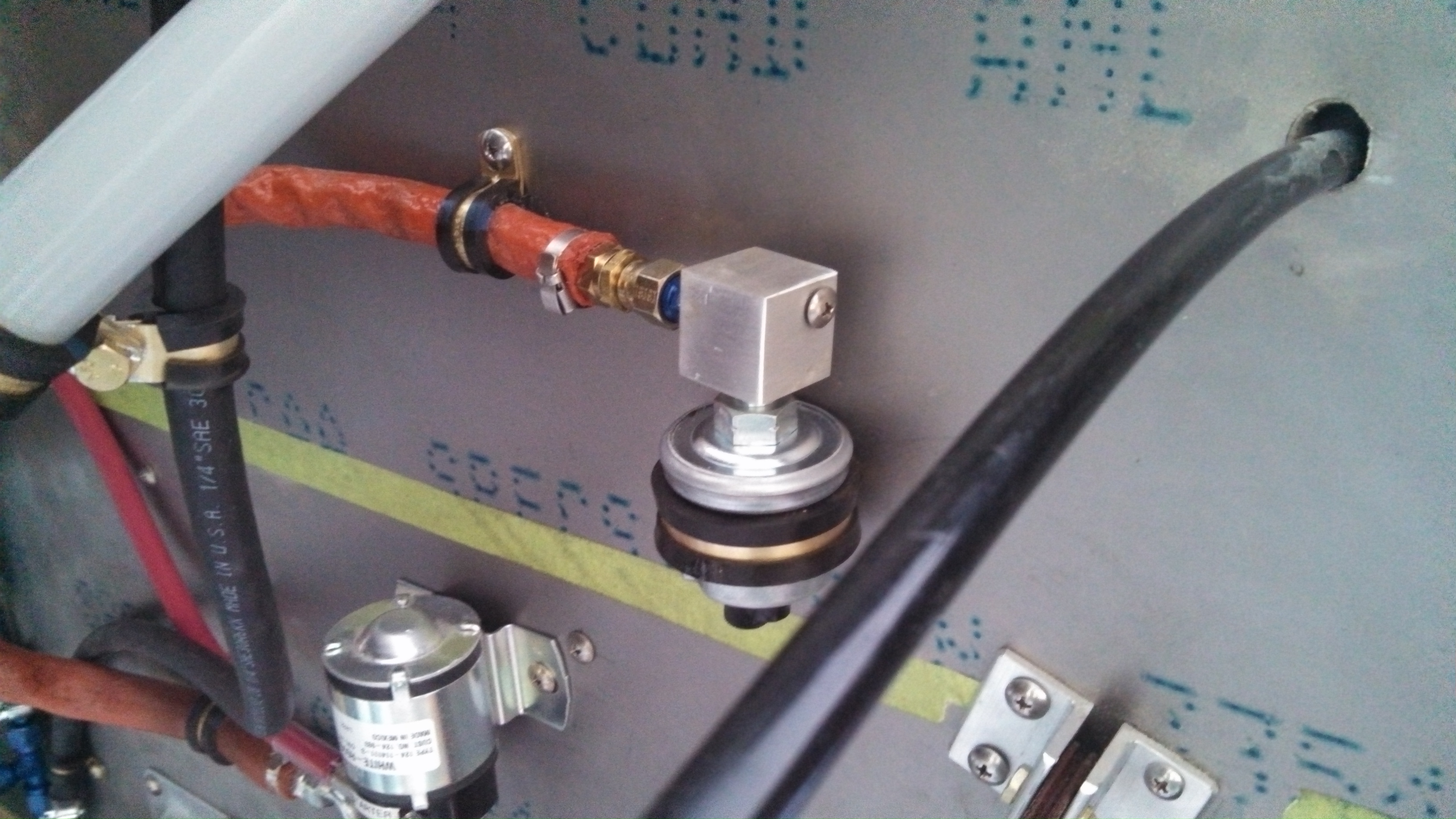
Many builders create a manifold that the various pressure sensors mount to. I created one of these but abandoned it due to space considerations. One of the things the manifold does provide is a convenient ground connection.

My attempt at accommodating this was to attach an aluminum tab to the sensor. But I just don’t like it.

So I got a piece of 1″ stock, drilled and tapped it for the NPT fittings and an 8-32 screw for a ground connection.

13.6 Ground blocks

This entry is part 27 of 67 in the series 13 - Electrical / Instruments

There are a few places that need ground connections. Engine side of the firewall, cabin side of the firewall and cabin side of the canard bulkhead (front of the cabin behind the instrument panel). One traditional metal aircraft, the frame can be used. But on a composite aircraft, that’s not an option.

There are a number of pre-made ground blocks available from places like B&C, SteinAir and Aircraft Spruce. But these can be pretty pricey and most use Faston connectors. I prefer ring terminals. So I decided to make my own.

I picked up a 12″x1″x.25″ block of copper from McMaster-Carr. Drilled out a 5/16″, 3/8″ and 11 holes for 8-23 screws.Next, I countersunk the holes for the 8-32 screws and tapped them out. Then cut them into three 8″ blocks.

Then I simply screwed in the 8-32 screws.


Installed.

I’m a little worried about corrosion though. John Tvedte plated his with a tin solution. So the next time I put in an order at Mouser, I’ll probably pick up some.