12.4.2 Exhaust Fairing

This entry is part 39 of 50 in the series 12 - Engine / Propeller

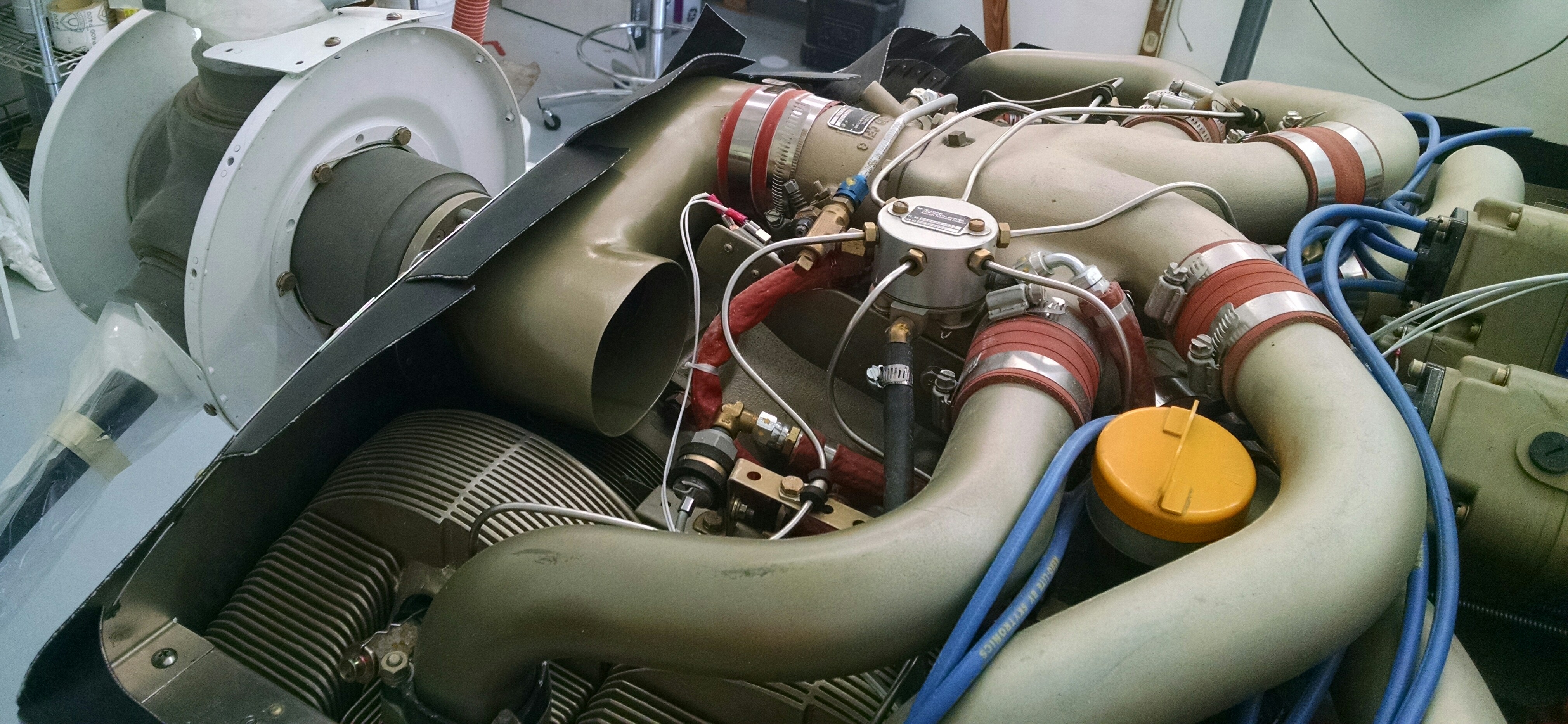
A while back I installed the custom 3 to 1 exhaust and made the cowling cutouts.

2013-06-06 IMG_20130606_151451_456

The manual says a 1/4″ clearance but Malcolm says that close and the glass starts showing signs of charring. He recommends 1/2″.

2013-06-08 IMG_20130608_101139_670

It’s a minor thing, but I think it will look and function better with some fairings forward of the exhaust. Not only will it be more aerodynamic, but it should be another path for air to exit the lower cowling.

My initial plan was to make the fairing out of blue foam and simply cover it with some BID. But Malcolm advised against that. He said that method would result in unneeded weight (doesn’t sound like much, but I guess every little bit counts), be a pain to cover and wouldn’t be as effective in being an efficient exit for air. He suggested in making a form, covering it on the outside, cutting away the cowling from the inside, removing the form and then adding fiberglass layups on the inside.

My first attempt at the forms was to use a mailing tube of the same diameter at the exhaust pipe.

2014-01-04 IMG_20140104_163352_990

But that didn’t work very well so I used some blue foam, formed it to the correct shape and used 5-minute epoxy to attach it to the bottom of the cowling.

2014-01-16 IMG_20140116_110719_374

Then to aid in making a consistent radius, I whipped up some sacrificial micro. I call it “sacrificial” because it will be removed from the inside once I cut away the cowling on the inside.

2014-01-17 IMG_20140117_105204_296

Then I covered the forms and radius with duct tape.

2014-01-17 IMG_20140117_110138_167

I applied 2xBID over the forms. That’s really not enough for a rigid structure but it’s only to get the shape defined.

2014-01-17 IMG_20140117_150229_588a

Once the layups cured, I removed the cowling and then began working from the inside to carefully cut away the cowling under (above?) the foam. This took a while because I didn’t want to cut through the fairings. So what I did was to make very shallow cuts well inside of the fairings and removed the cowling which exposed the blue foam.

Then it was time for another Hangar 18 trick… Acetone. Pour a small amount on the blue foam and it dissolves. Then just work and the remaining cowling with carbide burrs and some 24 grit on the grinder.

2014-01-18 IMG_20140118_113508_532

Now it’s time for the reinforcement. One layer of Triax and two more BID gets applied to the inside. The result is a fairing that’s roughly the same thickness and strength as the cowling itself.

Here’s the cowling back on with some rough cuts for the opening.

2014-01-19 IMG_20140119_112123_048

I fussed about what the final cut should look like. If I made it to have a consistent 1/2″ clearance to the pipe, it would have a funny shape. If I cut it to have a nice, symmetrical, pleasing shape, it would be too close in some places and too far in others. I spent about two days worrying that issue.

2014-01-19 IMG_20140119_151820_442

In the end, I split the difference. If the places that it’s too close start to show charring, I’ll trim it back.

Once I made the cuts, I started filling process.

2014-01-20 IMG_20140120_113121_706

All filled, sanded and ready for primer.

2014-01-24 IMG_20140124_154645_7042014-01-24 IMG_20140124_154713_8532014-01-24 IMG_20140124_154725_523


A comparison (Before & After)

2013-06-08 IMG_20130608_101139_670 2014-01-24 IMG_20140124_154645_704


12.3.6 Cabin Heat Damper Control

This entry is part 40 of 50 in the series 12 - Engine / Propeller

Like the Oil Cooler inlet damper, I was going to control the damper (or diverter) for the outlet to allow the heated air to dump overboard or into the cabin.  I had the servo and servo controller all set. But I couldn’t get a good mount for the servo and the damper.

I tried different size gears but the location and orientation of the damper prevented me from finding the correct position for the servo.

In the end, I had to fall back to the old standby of using a cable from the cabin.

I took the arm that I had originally made and put a cable stop on it.

2014-05-11 _20140511_172206

The I ran the cable from the copilot side of the keel just under the instrument panel, through the canard bulkhead, up, over and down to the outlet damper.

2014-05-12 IMG_20140512_194908842 (Large)

I oriented the cable so that when the control is pushed in, it will direct the heated air overboard. When you pull it, the air will be directed into the cabin.

Here’s the control end of the cable.

2014-05-28 IMG_20140528_084725635 (Large)

Now that I’m looking at this, I think that I’ll remove and paint it with the interior paint that I’ve been using.


12.99 Induction Air

This entry is part 41 of 50 in the series 12 - Engine / Propeller

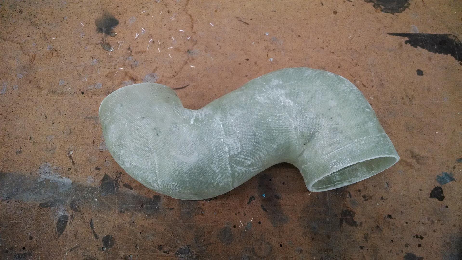
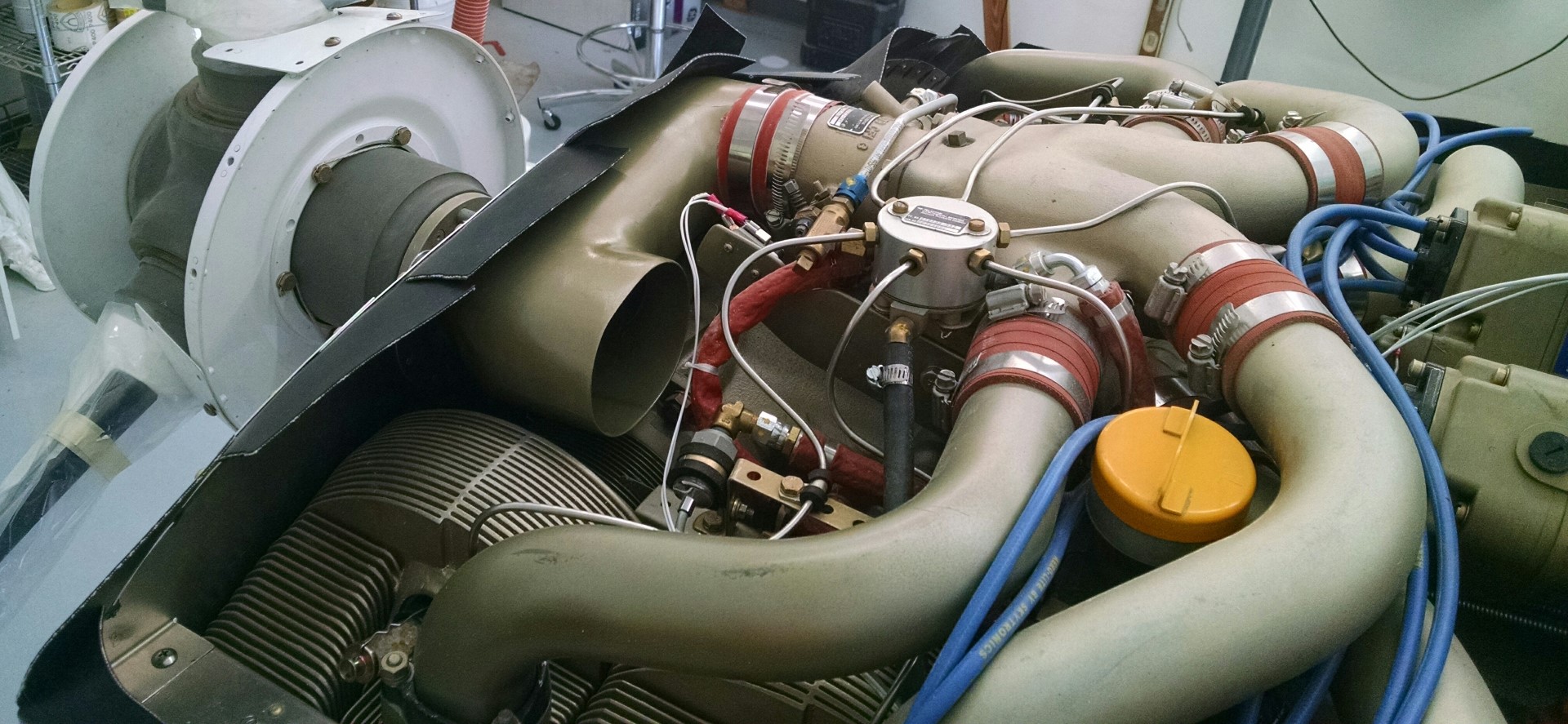
In a standard Continental IO550N installation, the way the engine gets air is through a “U” shaped duct that takes the rearward facing fuel injection servo and points the intake forward (remember the engine is in backwards).  Since I’m going a different type of plenum, that part won’t work for me.

An added issue is that the air is pulled directly from the upper area (which is supposed to cool the engine as it is pulled down) and there’s NO AIR FILTER!

So I had this idea that I would make a NACA duct on the bottom, put an air filter down there and somehow create some ducting to get that clean air up to the top of the engine.

I started with the part that I thought would be hardest. Making the ducts to get the engine intake extended to the lower cowling.

So I used a trick that I learned from Malcolm for fast prototyping. Using some leftover blue foam, I made a slightly smaller version of the duct. Malcolm’s next door neighbor builds funny cars and has a lot of experience moving air to 1,000+      horsepower engines. He said that squaring off the outside radius of the turns improves the airflow. So I squared off the outside part of the turns.

_20140709_162434 (Large)

The next step is to cover the foam with duct tape. But with the curves on this part, that didn’t work too well. So I used electrical tape instead. Because it’s softer, it was able to make the turns better. Then I smeared vasilene over the part and covered it with 4 layers of BID.

Once the epoxy cured, I poured acetone through the part which dissolves the foam. Then you just remove the tape and you’ve got your part.

IMG_20140724_064107520 (Large)

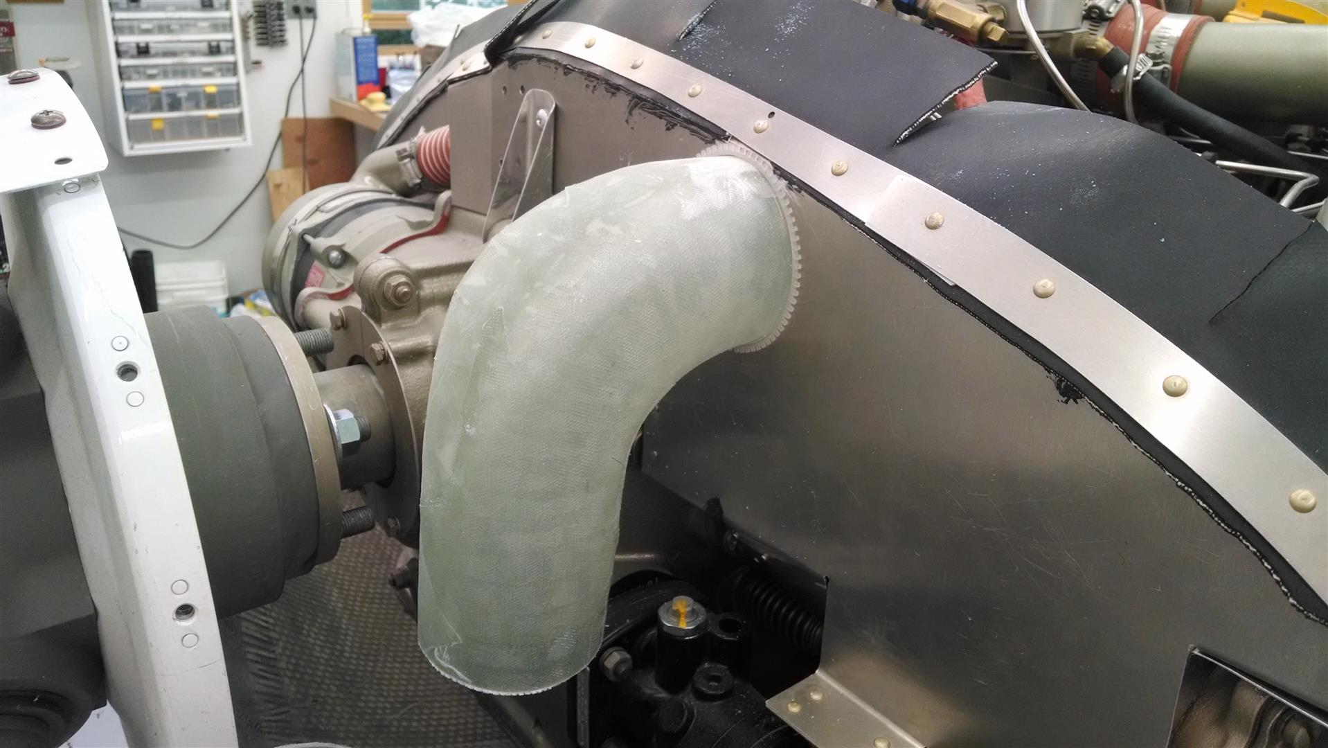
The next part is the elbow to turn towards the lower cowling.  By comparison, this is an easy part to make. Once again, I squared off the outside radius.

Then I cut a hole in the aft baffle and joined the two parts with a friction slip-joint. I added a tab to assure it would stay in place.

IMG_20140726_073803973 (Large)IMG_20140726_073756481 (Large)

All in all, I was feeling pretty good.

I picked up a 11″x6″ K&N generic air filter from the auto parts store, measured it and (this time) used plywood to make the mold for the filter box.

This would connect to the NACA on the lower cowl. Then I would make some ducting to get the air up to the elbow.

And that’s when I figured it out… There’s just no room! The amount of space between the engine (and engine mount) isn’t big enough to allow for a submerged NACA.  Let alone the almost 4 feet of ducting to get it up to the engine. I spent a lot of time researching various solutions but I just couldn’t figure out a way to make it work and not lose any performance.

So I had to drop back and punt. I made a U and I’ll pull air from the upper plenum without a filter. 🙁

IMG_20140809_181956766 (Large)IMG_20140810_172101357 (Large)

I went ahead and painted it so at least it looks pretty.

_20140818_162112 (Large)

12.99 Engine Woes

This entry is part 44 of 50 in the series 12 - Engine / Propeller

Since starting the engine for the first time, I’ve run into a bit of a problem.

It runs okay at higher idle speeds but it doesn’t want to run at speeds that the book says it should run at. When I first ran the engine, I couldn’t get it to run under about 1,200RPM. And I had to pull the mixture to about 1/2″ short of cutoff.

So I borrowed the fuel pressure gauges from the factory hooked them up.

2015-05-20 IMG_20150520_130951606

The engine manual says that at 600RPM the fuel pressure should be 8-10 PSI with the mixture full rich.  At 1,200RPM, I was seeing half that… and I had to have the mixture pulled out just to get that.

I increased the fuel pressure by a half turn and leaned the idle mixture by a half turn then ran the engine and checked the pressure. The pressure went up, the mixture didn’t have to be leaned as much and the engine could run at a little bit lower RPM.  Finally after FOUR turns on the pressure and and four turns on the idle mixture, I can run the engine at about 800RPM with the mixture full rich and a fuel pressure of about 11psi. If I go any further, the engine doesn’t run as well.

Since I was close, I decided to try a full power run.  The book shows full power being 2,700RPM.  But stationary on the ground I should only hit about 2,650RPM.  But when the throttle was pushed in all the way, 2,100RPM was as good as it got.

Clearly something is amiss.

I talked with Continental when I was at Sun-n-Fun and they suggested having a mechanic that’s familiar with Continental fuel systems look at it. But there isn’t one in Sebastian. The nearest one is in Sebring and he can’t make the two-hour drive over until the end of May.

I was talking with my A&P of many years and he said “Don’t pay anyone to look at the engine until you’ve had the fuel pump sent out and checked.”  And he was pretty adamant about it. I started looking for shops that do this work and the first one I hit basically said that since the engine has been sitting for four years the seals in the pump and manifold can dry out and get cracks which can cause some very strange behavior.

I pulled the fuel pump and fuel manifold (spider valve) and shipped them to Aircraft Accessories of Oklahoma.  Ken called me the day the parts arrived and said the fuel pump was “perfect”.  The only thing wrong was that the pressure was dialed up too high. I asked him if it was about four turns too high. He paused and said “uh… yeah. How did you know?” :-)) The manifold has a rubber diaphragm and it was “a little stiff” so it was replaced.

He said that I probably will never get a smooth idle at low RPMs because of the lightweight prop.  He also said the only other thing that could be wrong is the throttle body (fuel metering unit) and that if it didn’t run properly after reinstalling the parts that I should call him.

When the part arrived, I installed them and hoping for the best, fired up the engine… with the exact same results (low unmetered pressure, inability to idle at lower speeds and running very rich). I talked to a bunch of people and the consensus was that the metering unit was allowing too much fuel into the cylinders (making them run rich) which did not allow the pressure to build up (low pressure). So contrary to the official Continental Service Information Directive, I began adjusting the idle mixture by leaning it a half turn and running the engine.  The engine ran leaner, the pressure was higher and it was able to run at a slightly lower RPM.  Seems like the right track.

EIGHT TURNS later, the engine is idling at about 800RPM (a bit rough) with the mixture full rich and about 10.5psi unmetered pressure.  Well, I’ve been here before.

So then a full power run was done. The engine hit about 2,650RPM but then dropped to around 2,575.  Because the RPM dropped after peaking, it indicated the prop governor was now limiting the RPMs.  I backed out the prop governor and did another full power run and was able to maintain 2,650RPM.

That’s great… But the fuel pressure was very low for that power setting.

Now there’s an adjustment for this (high pressure adjustment).  But that adjustment will throw off the low pressure adjustment.

At this point, I’ve been fighting this since March.  I’ve spent about 18 days working on this and pretty much nothing else. It’s time to call in experts. Another builder had similar problems and called in Leading Edge Aviation from Tampa. I put a call into them and we made plans for Jonathan to meet at the plane.

When he came in to work on the other builder’s engine, he arrived at 9am and spent the day here.  But he told me that he’d arrive around 5pm!  I asked why and he said that it wouldn’t take very long (the other builder had a twin turbo-charged version of the engine). I was still surprised… and skeptical so I made sure that I had plenty of lights available.

So the day came but he was delayed a bit and ended up landing at around 6:15. He bought his own gauges and (small) handful of tools.  So we pulled out the plane and started it up. While he did get a pressure reading at 600 RPM, it was pretty ugly. He was working the throttle to keep the engine from stalling and he RPM was bouncing around so much that he would have to yell “NOW” whenever the engine touched 600RPM so his co-worker could read the pressure. Which needed tweaking along with the idle mixture. But not much.  At least I got that right.

Once that was set, we ran the engine up to full power and then the metered pressure needed adjustment… Which required quite a bit of adjusting. But that required going bach and adjusting the unmetered pressure and idle mixture adjustment. After only about an hour, it was finished!

Bob (another builder who’s building a twin) was on hand to observe pointed out “I told you that you should have called them two months ago.” And he did… And I should have. So I bought him dinner. Next time I’ll listen to Bob.

Time to begin taxi testing.

Fouled injectors

This entry is part 46 of 50 in the series 12 - Engine / Propeller

After the first few flights, I had Malcolm open up the fuel filter and clean it out. I cleaned out the tanks as best I could before and after they were sealed, but you can never get all the debris out. So cleaning out the fuel filter after a few hours is called for.

Malcolm reported the usual amount of crud that he sees in the filter at this stage.

At about the 15 hour mark on my Phase I flight testing, I had a cylinder come up cold during the runup. Now I’ve seen this more times than I count.  It’s always a fouled plug that is usually from idling full rich for too long.  The standard approach is to run up the engine and aggressively lean engine.  And has so many times in the past, it cleared the fouled plug.

But then about two flights later, I had two cylinders come up cold on the run up pad. Now that’s one I haven’t had before. I leaned out the engine at run up power to no avail. After a few more attempts the cylinders were all firing properly again. I made a mental note to make sure and lean the engine for ground operations like I have been with the Cessna.

Two flights later, it happened again. But this time I was only able to clear one of the cylinders. So I checked the mags and discovered that the cylinder was dead for both mags.  When it’s a fouled plug, it’s usually the bottom plug so I should have seen power on the top plug. Which meant that it must be a fouled (clogged) injector. Oh well.  Back to the hanger.

I pulled the cowling and removed the injector for the offending cylinder and sure enough, it was clogged. I could not see light when looking through it. I got a paper towel and blew through the injector but it wouldn’t clear. I tried a few more times and still couldn’t clear it. While I was walking over the service center, I tried a couple times and it finally cleared. But since I didn’t have the paper towel over the end, I wasn’t able to identify what the material was.

I reinstalled the injector and cranked up the engine and all six cylinders were firing away so I made another flight.

The next morning when I started up, I had two more cylinders that were not firing. A mag check showed that it wasn’t the plugs which meant that I had two more fouled injectors.  So I called Malcolm to come out and give me a hand. While I was pulling the five remaining injectors he was removing the fuel filter.

I cleared out the injectors and then I heard Malcolm say “Check this out”. I looked at the fuel filter in his hand and it was about half full of crud. He cleaned it and this is what came out of the filter.

2015-09-24 IMG_20150924_101057284

He said that was two to three times what he found the first time he cleaned the filter. Our guess is that there was a pocket of fiberglass dust that was stuck behind one of the baffles and that after about 10 hours of flying it got flushed out.

When the filter was reinstalled, we disconnected the fuel line at the servo and directed it into a container. Then I ran the fuel pump for a few seconds. We got a small amount of crud. Emptied the container and did it again. Clear fuel this time.

Hooked the fuel line back up and the engine ran fine.

So I’m going to be checking the fuel filter about every 5 hours for the immediate future until it shows clear.


Engine Dehydrator

This entry is part 45 of 50 in the series 12 - Engine / Propeller

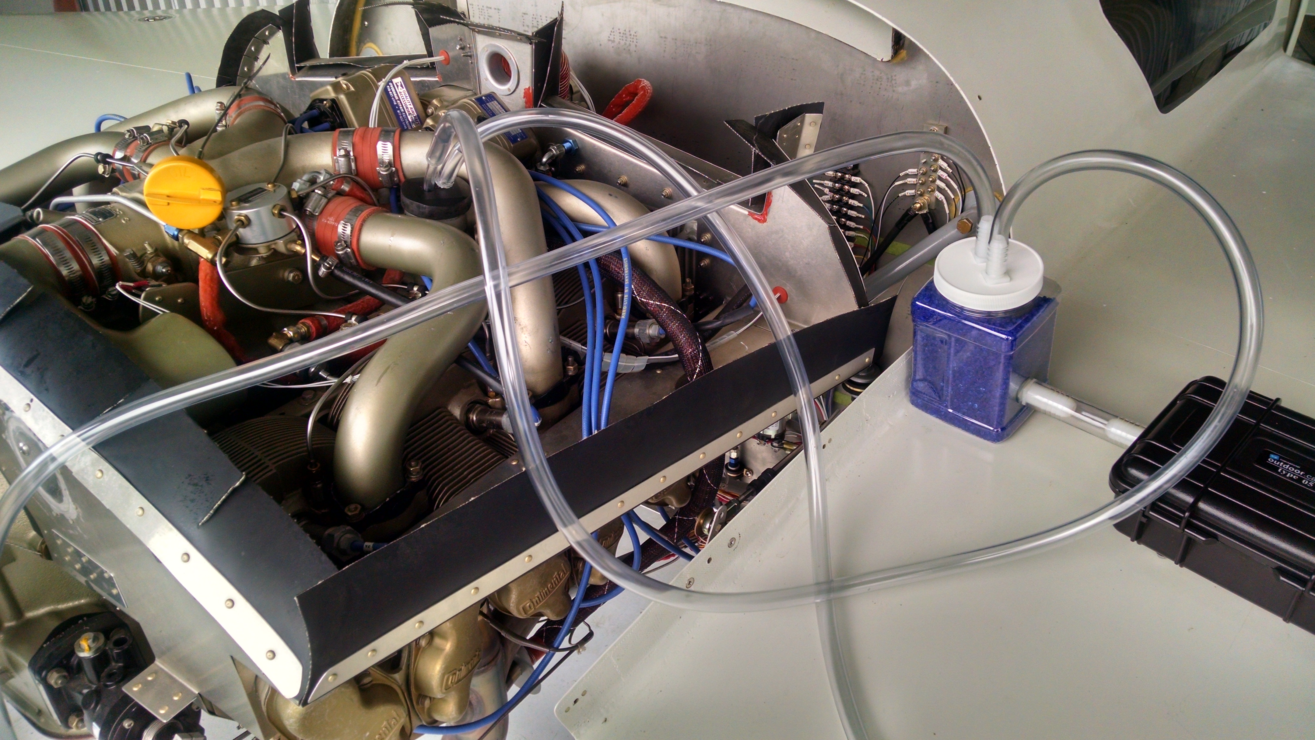
One of the things that is bad for engines is moisture (that’s why all the aircraft boneyards are in the desert). A fellow member of the CPS (Cessna Pilots Society) has built an engine dehydrator. That I’ve been using for a while now.

You connect the tubes to the oil filler port and exhaust pipes. Then when you switch on the box, a small air pump recirculates air into the engine after passing it through a bottle of desiccant. The pump runs until the humidity gets to 5%.  Once the humidity rises to 10%, the pump turns on again so that in air inside the engine is always between 5-10% humidity.

2015-07-04 IMG_20150704_173935480_HDR 2015-07-04 IMG_20150704_173940633_HDR

I’ve seen some of these homebuilt systems that run either continuously or on a preset timer. I like this one because it actively monitors the moisture level.

Not sure if it’ll make any difference but it’s a lot more humid here in FL than it was in IL.

If you’re interested, contact Jerry Olson at jolsonpt38@sbcglobal.net. He will need to know what type of engine and if you made any modifications that he needs to accommodate (like my breather tube into the exhaust).

12.99 – Oil temperature and heat challenges

This entry is part 47 of 50 in the series 12 - Engine / Propeller

I’ve been having an ongoing issue with oil temperature from day one. But unlike most builders, my problem is the oil temps are too low.  Around 150 is about as high as it gets during flight.  For a long time I didn’t notice it because I was only keyed in on if it got too hot.  So it didn’t register that it was running too cold. The Continental operations manual says between 160 and 180 is normal in cruise oil temp.

Another problem is my idea of using a servo to control the damper to block the outside air from the nose oil cooler and recirculate cabin air through the oil cooler failed miserably. The problem is that the NACA duct for the nose oil cooler is useless.  Because the surface of the fuselage at the nose is angled in, the oncoming air goes directly into the oil cooler.  The NACA duct does not reduce the pressure or speed of the air.  As a result, the servo can not overcome the force of the air and remains retracted. So on our recent trip from Chicago, the “heater” was putting out about 40F air into the cabin.

I could try a stronger servo, but because of how the damper attaches to the pivot, I’m worried that it will break the damper off the pivot.

These two problems are somewhat related.

I thought that maybe the vernatherm (thermostat which controls whether oil goes to the cooler) for the nose oil cooler was stuck and was always allowing oil to go through the oil cooler. To test this I blocked the air inlet for the nose oil cooler. That helped some. But it only went up about 10 degrees. But it also allowed the damper to move which permitted cabin air to run through the nose oil cooler.

So I decided that the easy fix was to build a winterizing kit. This would be an easily installed (or removed) cover for the nose oil cooler. Since the nose oil cooler is only for cabin heat and the engine mounted oil cooler is more than capable of keeping the oil cool, closing off the nose NACA duct isn’t a problem.

Here’s the Mark 1, Johnston Velocity Winterizing Kit.

2016-12-02-img_20161202_160846 2016-12-02-img_20161202_160832

If needed, I can close off the holes in the baffle to further reduce outside air.

Installed (I’ve started prepping it for paint so there’s some filler on it).

img_20161215_161355 img_20161215_161400

When I did a test flight with the Mark 1 JVWK, this was temperature of the air coming out of the heat duct.

2016-12-03-img_20161203_150501

That takes care of the cabin heat issue.

For the low oil temps, I should replace the vernatherm that controls the oil to the nose oil cooler, but I can’t see a part number on it and replacing it requires removing the oil filter, oil filter adapter plate and maybe disconnecting the oil lines. At some point, I’ll get the part number and swap that out, but for now I’ll start with the engine oil cooler vernatherm.

I picked up a new vernatherm (used, actually) and tested it.  This is done by putting it in oil on the cooktop, heating it while verifying that it opens at correct temperature. The vernatherm in the engine is stamped “77C” which converts to 170F.  It tested correctly.

Getting to it is not the easiest thing in the world.  It’s located almost directly above the engine mount.  But an hour later, the replacement was in and I was doing an engine run-up leak check. Inspection of the area showed no leaks. So I replaced the cowling and cranked up the engine for a test flight.

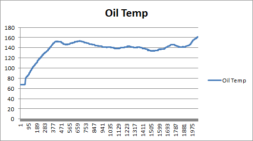
This graph is from a flight about on month ago.  The OAT was 60F, altitude of the flight was 4,500′ and the engine was running at 25″ MAP and 2,500RPM.

flight-1

Max oil temp was around 150 at the beginning of the flight and it drops down to 140 in cruise.

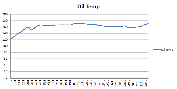
This flight is after the new vernatherm was installed. The only difference was this flight was at 3,500′ instead of 4,500′.

flight-2

Max temp in cruise was 171.  Yay!  RIght in the middle of the allowable range. I’ll test the old vernatherm soon and see how it behaves.

12.99 Cabin Heat

This entry is part 48 of 50 in the series 12 - Engine / Propeller

Update at the bottom of the post.

Even after the recent modifications, I’ve still got issues getting cabin heat. Here’s what (I think) is happening:

While I am getting hot air from the system, I’m not getting enough volume. On our recent flight to Atlanta, Ann was getting cold so I turned on the heat.  After a while, it didn’t seem like it was getting any warmer. I asked her to put her foot down where the air outlet was to see if any hot air was coming out. She said that she wasn’t feeling any but she wasn’t sure if she was checking in the right place. It’s down on the very bottom of the canard bulkhead between the rudder pedals but you can’t really see where it is.

On the trip back, while we were taxiing out, I turned on the heat and asked her to check if she could feel any hot air coming out. She said there was a definite blast of hot air. Once in the air, I had her check again. Nothing!

Hmmm.

Here’s what I think is happening:

On the ground, the damper which blocks the hot air from going out the bottom of the fuselage and diverts it into the cabin works fine. But once in the air, the shape of the outlet at the bottom of the fuselage creates a vacuum.  Because the damper doesn’t create an airtight seal in the duct, I think that vacuum is literally sucking the hot air out the bottom.

My solution is to create a lip or flange that the damper can seal against to block the air from being sucked out.

So while the nose gear doors were out, I disassembled the nose oil cooler ducts to access the damper. I sanded the duct area around the damper and then applied a liberal amount of release agent (AKA, Vaseline) to the damper.  Then I mixed up some epoxy, cabo and some flox and applied it to the duct around the bottom of the damper. Once it cured, I broke the damper loose and cleaned up the excess.

Because of the tight working area, I had to repeat this a few times to get the required coverage.

2017-02-14 IMG_20170214_1313582017-02-14 IMG_20170214_131445

Now I just need to test it out.  I’ll attach an extension duct to the co-pilot side outlet. That way I’ll be able to tell if this fix worked.

Update:

I connected a 6′ shop vacuum hose to the copilot side heater duct. The OAT was about 50f. With the outside NACA blocked and the diverter closed to allow heated air into the cabin and the fan on max, I was feeling hot air coming out at a noticeable flow.  It definitely needs more flow though.  I’ve got a pair of 1.5″ centrifugal fans that should increase that flow.  But that will be for a later day.

For now, I think that I’ve got enough hot air for anything above 30F.

Electronic Ignition

This entry is part 49 of 50 in the series 12 - Engine / Propeller

One of the things I was planning on when I started building was to install electronic ignition.

If you understand aircraft engines, please skip ahead “RESUME HERE” mark. 😉

The spark on aircraft piston engines is provided by a magneto. This is similar to the distributor on an (older) car engine.  The difference is that a magneto is effectively self powered. It generates the spark without any outside power required. That’s why an airplane engine can run even if the master power switch is turned off.

There are two magnetos which are connected to two spark plugs for each cylinder. There are two reasons for this: 1) redundancy and 2) two sparks burn the fuel mixture better than one.

There is also a big drawback to magnetos.  They don’t advance as the engine turns faster. Even car distributors did this. As a result, the timing on a magneto is a bit of a compromise. It’s set so provide adequate spark across the RPM range of the engine.

Electronic ignitions require power to generate the spark.  But they can create multiple sparks when they fire which burns the fuel even more completely.  And they will advance the timing as the engine turn faster.

RESUME HERE

G3i

At the time I started building, electronic ignitions were complicated affairs with multiple boxes and wires and required external power.  I didn’t like that so I was going to go with standard magnetos.  Then I heard about G3i.  This was a really interesting concept.  It used an external box and controlled the spark.  But it used the existing magneto.  Which means, if the box lost power or failed outright, then the magneto would continue operating in legacy mode. The only problem was it was only available in a 12v version. So I made provisions for one in my electrical system design, but waited to see if they would come out with a 24v version.

At the 2016 Sun-N-Fun I stopped at the E-Mag booth.  They had an electronic ignition which was literally a drop in replacement for the magneto. No external boxes!  And… It did not require external power.  It had an integrated generator.  Well sign me up! The owner of the company said that they were currently working on certification. I said I have an experimental aircraft. He said that he could get me one real soon and would appreciate feedback.  I said “no problem”. He said that should be able to get one of his “Non-certified” units in a couple of months.  “Great” I thought.

About a month later, I sent him an email and was told they are focusing on getting certification.  I said I didn’t need a certified unit and he said that they didn’t have anymore non-certified units but that I’m on the list and it should be just another month.  Over the next two years, I would check in and be told “couple months”.

To date, they still aren’t shipping a unit for a 6-cylinder Continental.

At Oshkosh that same year I stopped by the SureFly booth and talked to the owner, Jason Hutchison.  Basically the only difference between his ignition and E-Mag was that he didn’t have a generator integrated in his.  It required a 10amp circuit.  Okay, I can live with that. And it was about the same price as the E-Mag. But I wouldn’t be able to use my existing wiring harness.  He said they would be shipping in… wait for it… a couple months. He gave me his card with his personal cell phone number on the back.

I told him that whoever called me first would get my business. Over the next 14 months whenever I called he said that he was running behind because of whatever.  But he always told me what was holding him up.  And he was very forthcoming.

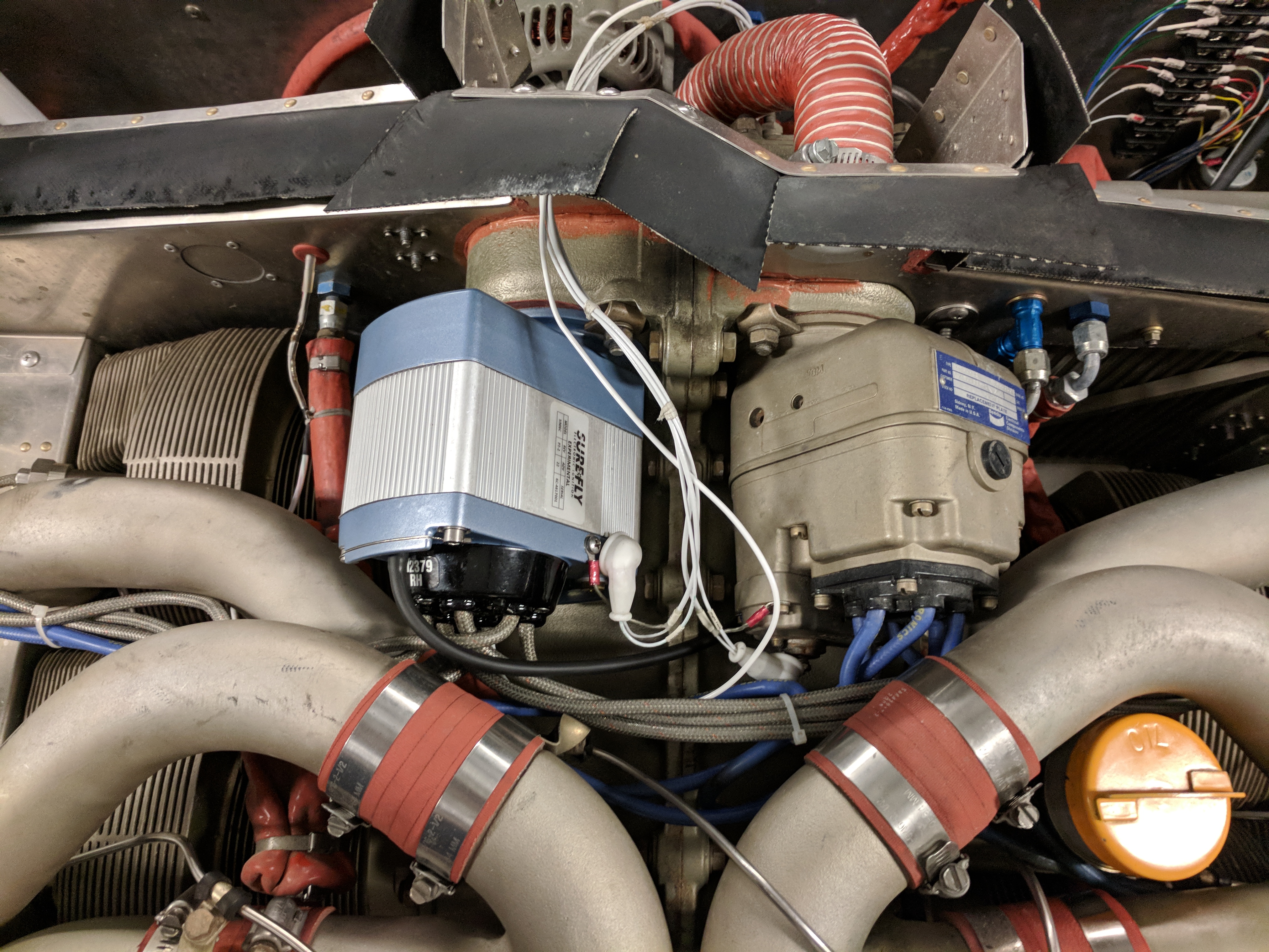
In December of this year, I received my SureFly SIM6C.

Then I had to get an ignition harness. I had no idea how much one would cost.  I figured a couple hundred.  Turned out to be closer to six hundred. 🙁

But that was for a complete harness (both magnetos).  So if anyone want a right magneto Slick ignition harness for a Continental 6-cylinder, let me know, it’s yours for $300 with free shipping!

I built the airplane but I purchased the engine. Whenever I do anything serious on the engine, I like to have someone that knows engines to work with.  My old A&P/IA from up in Chicago has semi-retired and now spends his time raising cattle and working on airplanes in Tennessee. I told him what I was planning on doing and asked if he would help and he said “Come on up!”.  And up I went.

Pictures of the Bendix magnetos:

2012-09-07 IMG_20120907_152840a

2012-09-15 IMG_20120915_164400

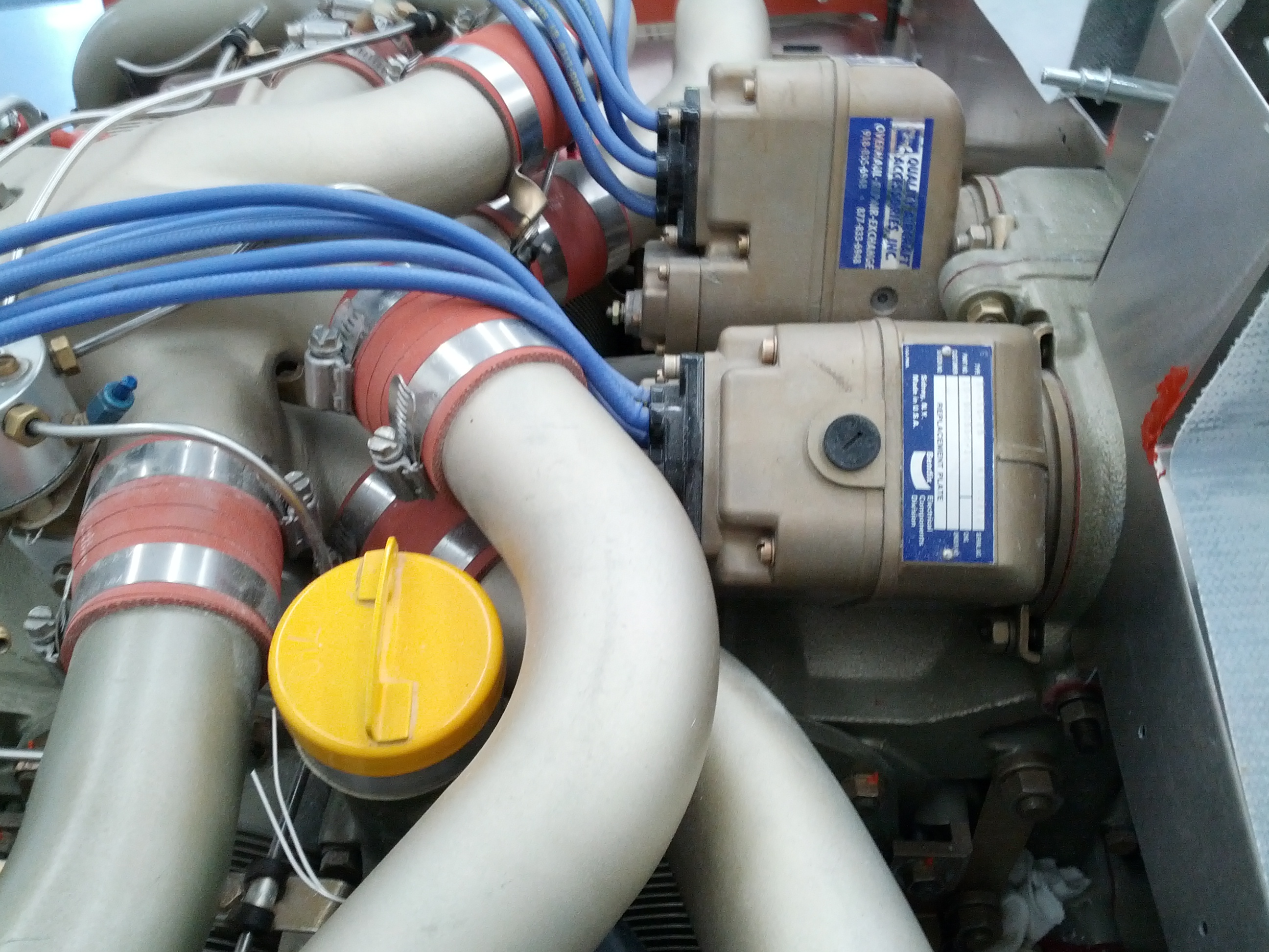
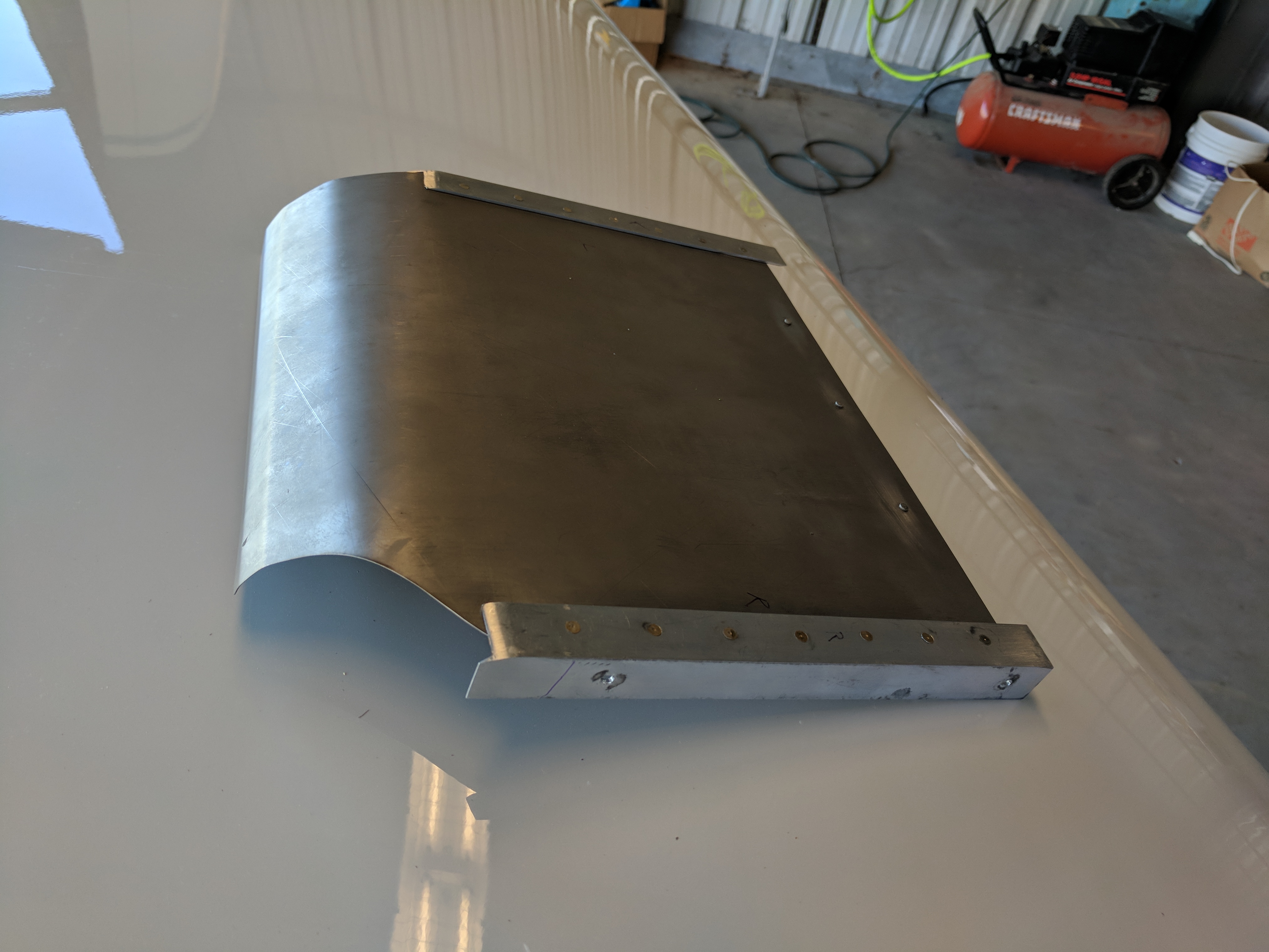
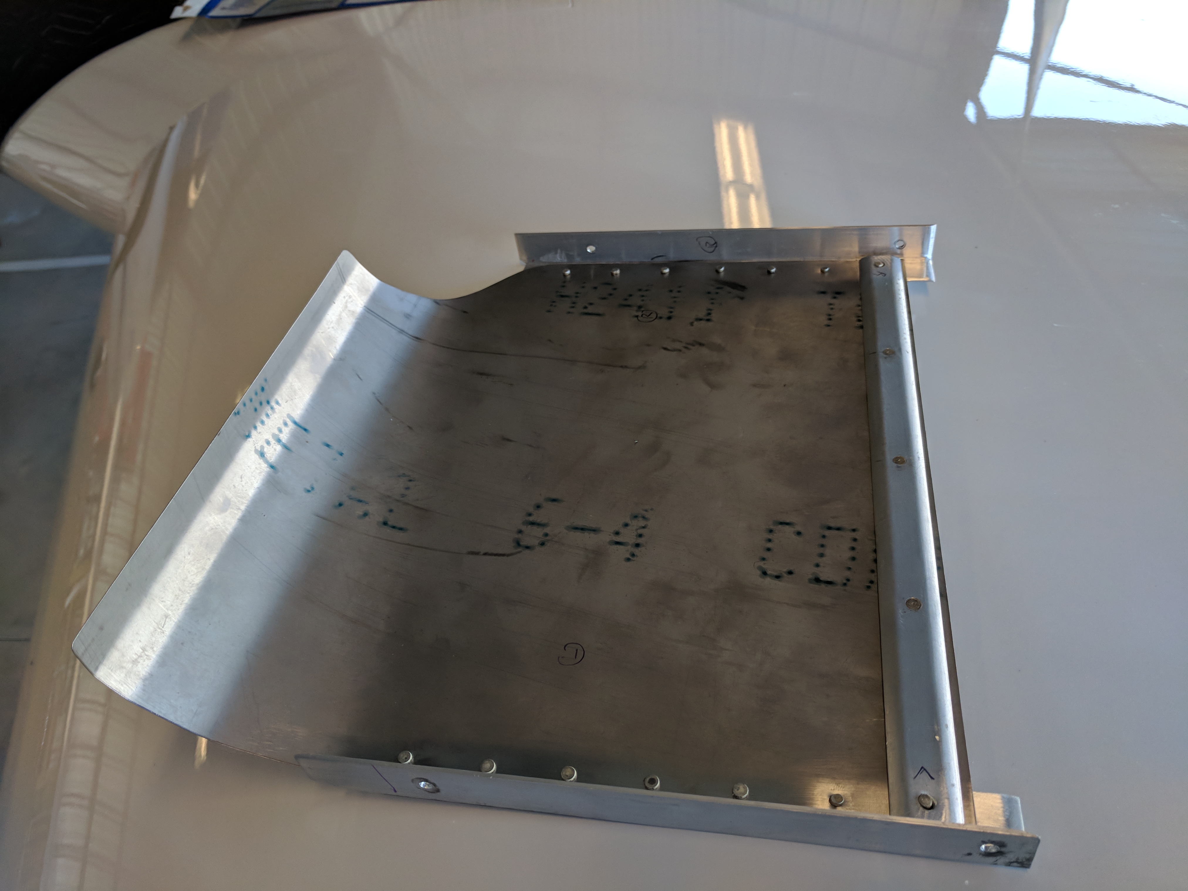
I flew up on Friday morning and at 8:30am we started pulling the old left mag (technically it’s the right mag because the engine is on backwards).  That’s when we started finding pieces of aluminum sheet.  It took me a minute before the light bulb went off in my noggin’ and I looked at the intake ducts on the upper cowling.  To kept the cylinder head temps even, I built a “diverter” to direct the incoming air down onto the cylinders.

2018-03-03 IMG_20180303_115720 It seems the vibration caused it to crack and come apart. So I removed what was left and then we installed the new electronic mag. When it was time to set the timing, Lynn said “we need to find the correct engine position”.  I said, “no problem, I’ve got it marked on the prop flange.” But the new mag wouldn’t fit in that orientation. So we had to re-clock the gear about 20 degrees so it would fit.

New electronic ignition installed:

2018-03-12 IMG_20180312_133249 2018-03-12 IMG_20180312_133257

The company that did my fuel system adjustments last spring had it all screwed up. So Lynn broke out his gauges and we set the fuel injection system pressures as well.

Once that was done, he hopped in the co-pilot seat and said “Let’s go!”.  You gotta love an A&P who’s not afraid to ride in a plane he just worked on.  🙂

We took off and started climbing. At about 1,000′ the CHT alarms started going off.  It’s amazing how much that diverter helped. I was having a hell of time keeping a couple of the CHT’s below 410. It was very bumpy so we returned to the airport. Once on the ground he asked if I wanted to go to lunch.  I said that I wasn’t comfortable with the CHT’s and that it was probably best if I took off now just in case I had to return.

So off I went.  I made it about 7 miles when I decided to turn around. I had one cylinder that had gone over 420 degrees! When I landed, Lynn asked what I wanted to do.  I said that I had been flying over two years without the diverter so I knew that I could keep the CHT’s under 400 (barely) without it. So that’s not the problem.  My fuel pressures and flow had been too low before he adjusted them, so that’s not it.  Which means it has to be this electronic ignition. So I said that we’re going to have to put the old mag back in.  He agreed.

So off comes the cowling.  I get started on disconnecting the ignition harness while he starts removing the mag.  He mentions that we’re going to have set the timing on the old mag.  I once again say that shouldn’t be a problem since I’ve already got the mark on the prop flange. He comes to a dead stop…  “What?” I ask.

He said “I thought you said that mark was for the new mag?”  I said “Yeah. It’s for setting the timing of the mag.” And then I get “the look”. You know the look.  When you think you know what you’re talking about but you really don’t?  THAT look.

He said “Don, the timing of you Bendix mags is at 22 degree BTC. You told me this new mag is supposed to be timed at top dead center.”  He continued:  “That would explain why the CHT’s were so high. And why we had to reclock the timing gear 20 degrees.”

To say I felt like a idiot would be an understatement.  But that right there is why I like to have someone who knows what they’re doing when I do engine work.

We re-clocked the mag gear, re-installed and re-timed the new mag.  Started up the engine and it ran fine (but it ran okay before so that’s not conclusive). Put the cowlings back on, loaded up and took off again.

This time the CHT’s for the hottest cylinders only sneaked over 410 and I easily got them back down under 400.

On the trip home at 7,500′ (500′ lower than the trip up) with the same OAT, I was indicating about the exact same airspeed (I was hoping for a little improvement) but my fuel burn was .5 GPH lower. I’ve only made one other trip so I’m still gathering data on performance.  After a couple more trips I should be to determine what improvements to expect.

One thing I’m surprised at is the mag check. On other airplanes I’ve flown with electronic ignition, when you do the mag check, the difference between the legacy mag and the electronic mag is HUGE.  The reason (as explained to me) is that when you shut off the legacy mag, you barely notice it because the electronic mag is generating so much spark that you don’t really notice the loss of the legacy mag.  But when you shut off the electronic mag, the old mag is the only thing generating the spark so the engine feels very rough.  I don’t see that with this mag.

When I got back home, I thought about how to make a diverter that wouldn’t crack again. I still have some titanium left over so I decided to try that.  It took a quite a bit of work to get the roll in the back but eventually made it. Hopefully, this one will last a little bit longer.

2018-03-03 IMG_20180303_153854

2018-03-03 IMG_20180303_153903

12.99 Engine induction air

This entry is part 50 of 50 in the series 12 - Engine / Propeller

My CHT’s (Cylinder Head Temperature) run hot.  This is not an unknown issue with a Velocity.  Keeping CHT’s in a manageable is an ongoing challenge with many piston engine aircraft.  Since the engines are air cooled, getting air to flow around the cylinders is key.

So here’s the Velocity engine setup for a Continental IO550 engine.

IO550 Right side view cowl 3

Air enters the upper plenum through the two roof NACA Ducts (upper right of diagram).  This air then moves down around the six cylinders cooling them (and also passes through the oil cooler) on its way to the lower plenum. The lower plenum air is the exhausted through the openings at the rear of the cowling in front of the propeller.

My configuration has one difference.  The engine exhaust is routed aft out the bottom of the lower cowling with fairings around each of the two exhaust pipes.  This is another exit point for the hot, lower plenum air. This should provide better cooling than the standard setup where the exhaust sticks straight down out the lower cowling.

IO550 Right side view cowl 4

One of the first things airplane owners do when faced with high CHT’s is to find and plug any holes in the baffling separating the upper and lower plenum. Those openings will allow cooling air to escape into the lower plenum.  I checked and plugged any holes and made sure there were no large gaps between the baffles and the cylinders.

Now what?

Normally, people look at trying to get more air into the upper plenum.  On a Velocity this can be a challenge that traditional tractor style aircraft don’t have to worry about. On your typical Cessna, Piper or Beechcraft, the upper plenum entrance is at the front of the airplane and it’s wide open. Not so on the Velocity.  Some builders have installed vortex generators on the roof to keep the air attached to the top of the fuselage making it easier to get into the NACA Ducts on the roof.  Some of these VG’s are so big they look like shark fins.

One of the things my good friend Malcolm Collier taught me was to think of cooling air like a length of rope; It’s a lot easier to pull rope out of a space than it is to push it into a space.  If you pull enough air out of the lower plenum, then more cooling air will have to be drawn into the upper plenum (assuming the openings are large enough and there’s no blockage).  To that end, some builders have installed vents on the bottom to provide additional exits for the hot air. But I already had that with my exhaust. I could add these louvers, but I don’t think that’s the solution.

Clearly there’s something else.

The Continental IO550 engine installation in a Velocity is somewhat unique. The induction air intake is unfiltered. While building, I started building a pipe to connect the intake to the lower plenum which would connect to a filter box that was then connected to an intake scoop or duct.  But the space was just too tight and by this point the modifications had piled up and I needed to finish the build and get in the air.  So I elected to stick with the plans.  I did build a small U-turn so the air was being pulled from the front instead of the back.

2014-08-18 _20140818_162112

Then one day during a short, local flight I noticed that I wasn’t fighting to keep my CHT’s down in the climb.  And in cruise they were much lower than usual. Once back on the ground, I discovered that the oil door was open.  I’m guessing that it wasn’t pressed all the way down and it popped open once the engine started. But why would that result in lower CHT’s?

Here’s my theory.  The oil door is located forward of the engine air intake.  I think that the open oil door provided a second air source which went mostly into the engine intake.  With the oil door opening providing induction air, that left more NACA air available for cooling.

IO550 Right side view cowl 6

A quick, back of the napkin calculation showed that the engine consumes about 6.5 cu/ft of air every second.  Which means that 6.5 cu/ft per second of cooling air coming in the roof NACA ducts is being consumed by the engine.  Now I don’t know how to calculate the volume of air coming through the two roof NACA’s.  But every cu/ft would matter.

Now the question is how to fix it.

I’m already in paint. So I would really like to not mess with the cowling.  But I’ve got to create an opening for the engine air.  I thought about making an oil door with a small scoop that fed a square duct on the underside of the upper cowling that then connected to the intake.  But the fuel distribution lines are about an inch from the inside of the cowling. The other problem with that is a scoop sticking up into the air just in front of the prop would disturb the air even more than is already is.

So it would have to be a small NACA duct that terminates just above the intake.  My old “U-turn” intake would have to be replaced with a box-type of intake that would accept the air from the NACA duct.

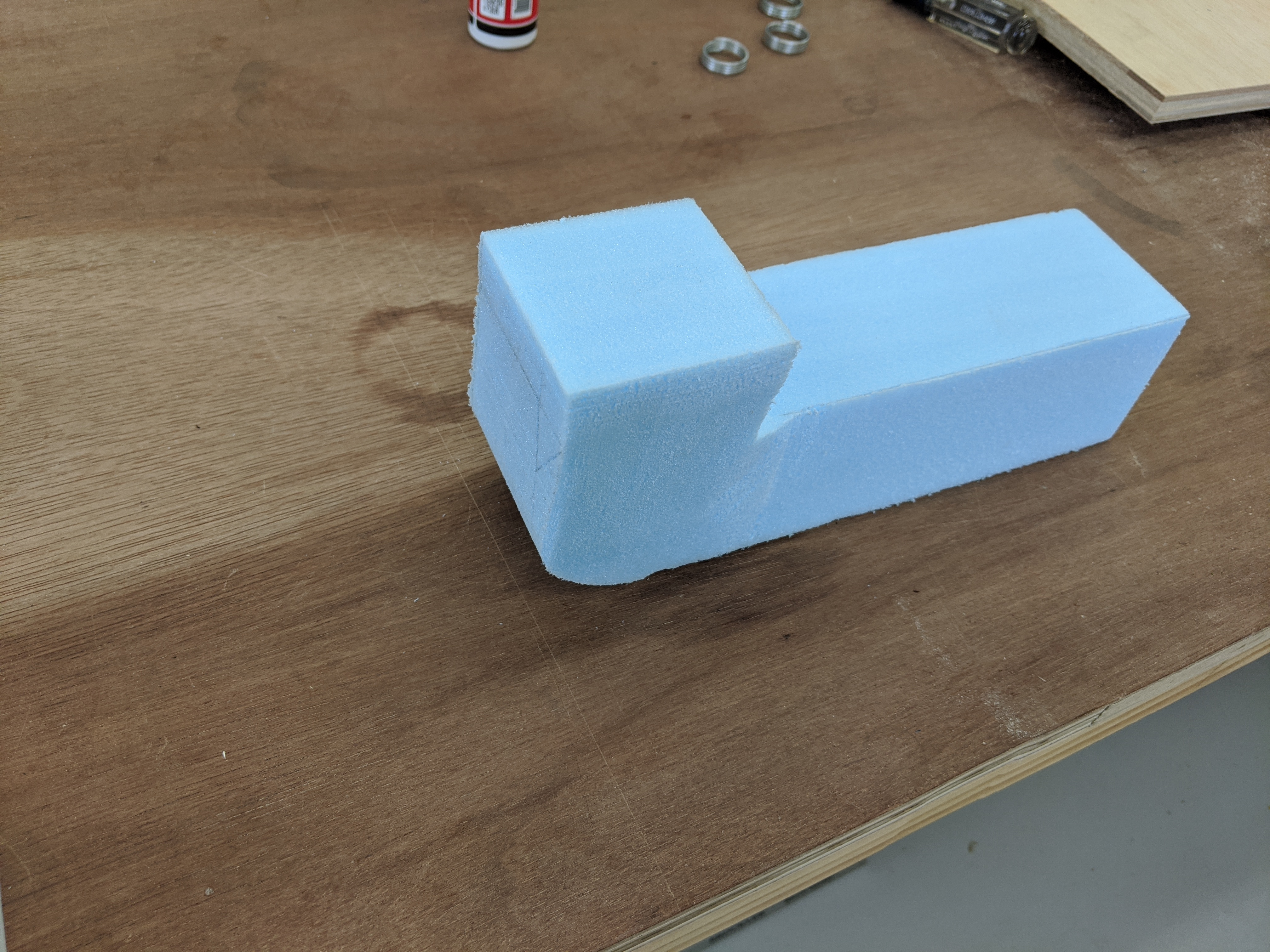
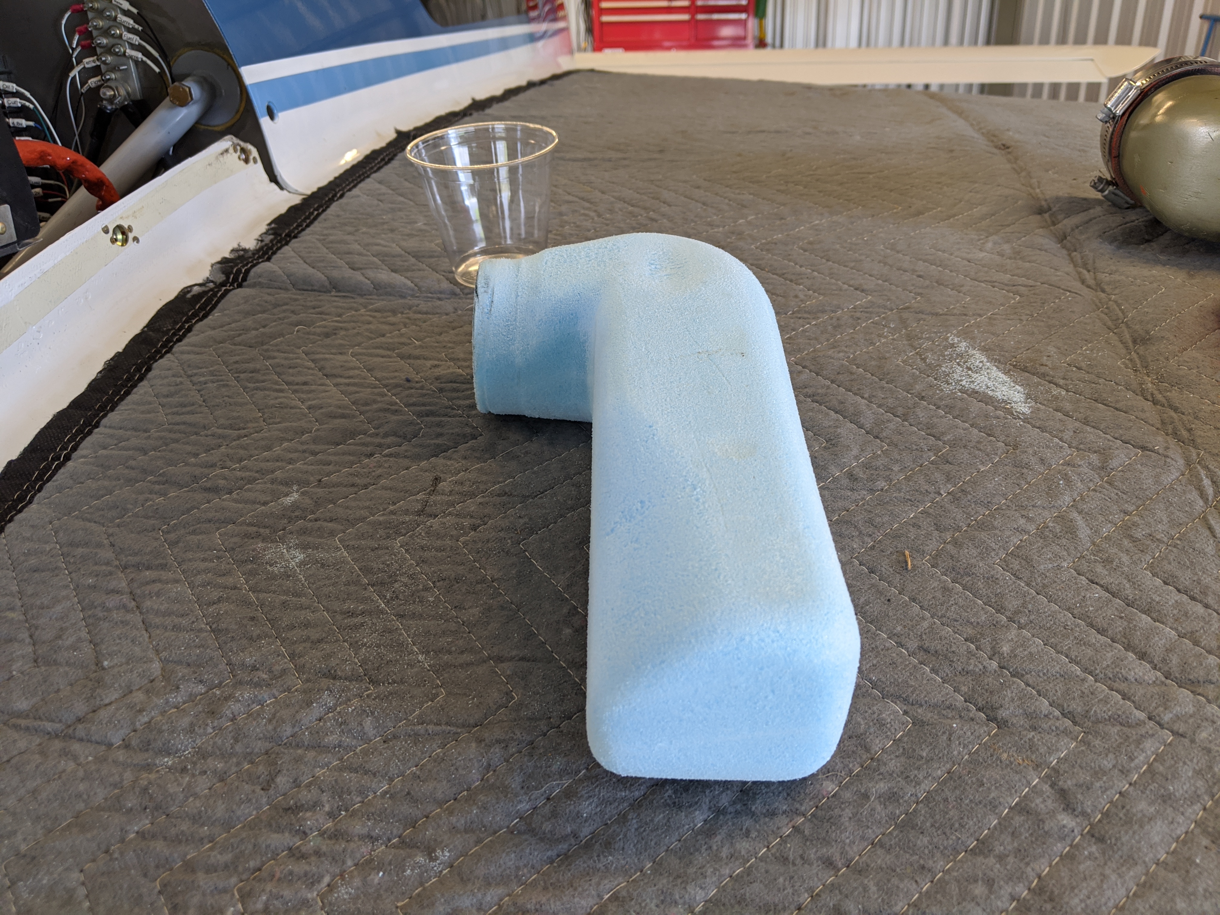
First order of business is to build the new airbox.  Just like the original U-turn intake, I started with blue foam.  Cut the basic shape on the bandsaw and then using Permagrit files I got it down to the shape I wanted.

IMG_20200407_143418    IMG_20200407_143443IMG_20200408_091254IMG_20200408_091248IMG_20200408_091243

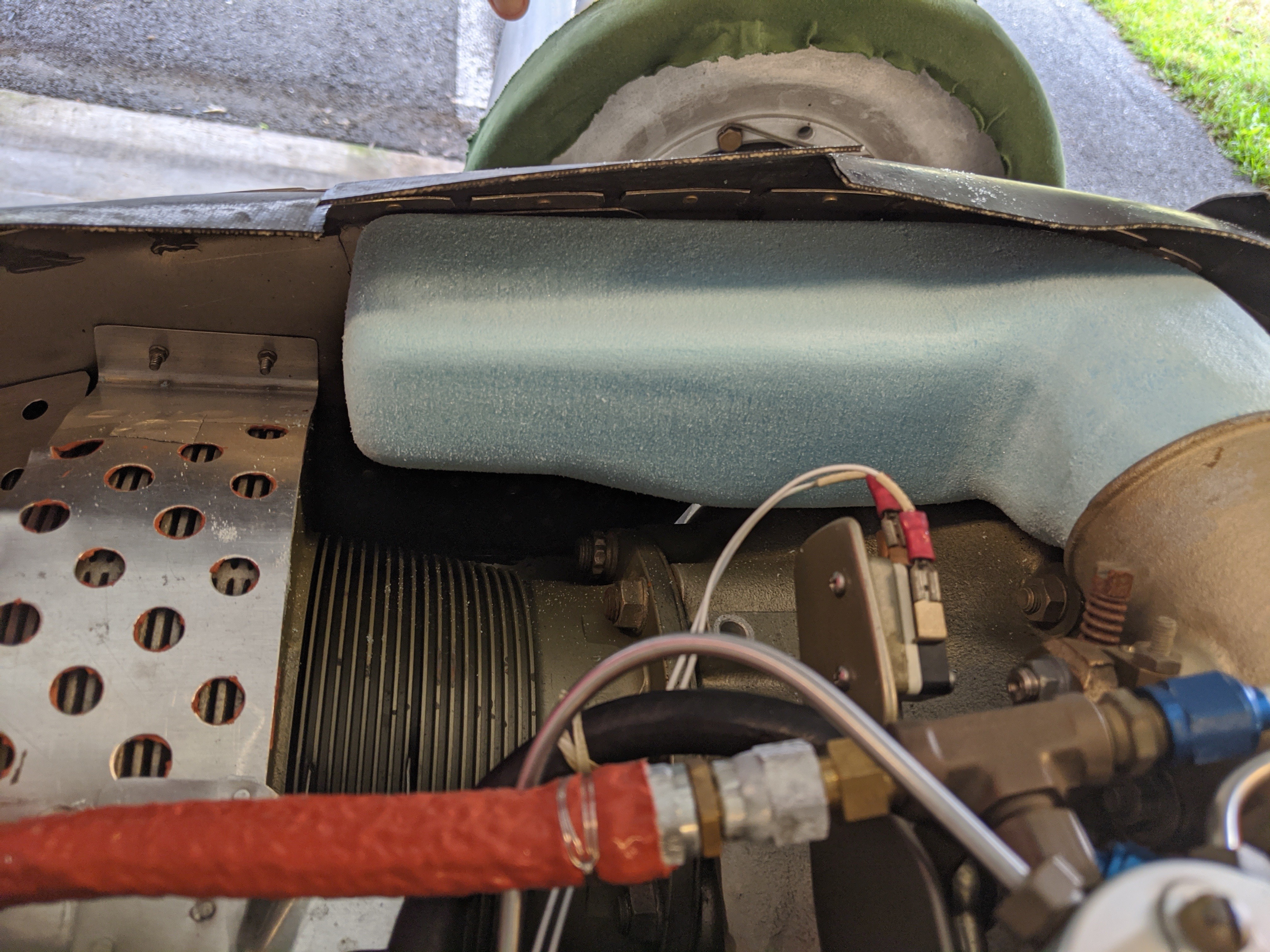
After a test fit, I had to create a couple of… divots to clear engine case bolts and screws from the aluminum baffle at the rear of the engine.

IMG_20200408_091232

Then the whole thing gets wrapped in duct tape and a few layers of BID to create the final product. Once the epoxy has cured, I poured lacquer thinner down the opening to dissolve the blue foam. Then I just pulled out the duct tape.  The first test fit of the new airbox revealed a problem that I ALWAYS discover: I make the foam blank the size I want the finished piece!  Which means it a little too big.  So rather than remake the whole part, I just ground out the divots and made them a little deeper.

IMG_20200414_095128

Then I began sanding and filling to make it pretty.  Because that’s how I roll.

Now that the airbox is done, it’s time to start on the duct. Because the engine intake is 2.75″ in diameter, that’s a little less than 6 square inches in area.  So I will want the NACA duct to have at least that large of an opening.  I decided on 4-1/2″ x 1-3/8″.  That gives me a little under 6.2 square inches of area.

Andy Millin’s Excel spreadsheet was used to determine the shape of the duct.

I laid out three layers of BID on a waxed piece of glass. These would be the sides of the duct.  Then I determined where the end of the duct should be and applied masking tape to the cowling and drew out the duct.


IMG_20200423_095100

I cut the back and sides of the duct and left the front of the ramp attached.

IMG_20200423_101914

The side pieces of the duct where cut so that they would be too high.  I slid them into the cuts for the side of the duct (I used three layers of BID because it was the exact thickness of the saw blade I used to cut the duct). Stir sticks cut to 1-3/8″ long were used to hold the ramp at the correct angle while the epoxy holding the sides to the cowling and duct ramp cured.

IMG_20200424_082410IMG_20200424_082438

Once the epoxy cured, I trimmed the top and bottom of the side pieces.  I left them longer on the back to create the channel that would feed the airbox. I rounded the bottom side of the duct and applied a few layers of BID to reinforce the duct. On the topside, I used epoxy/cabo to create a small fillet at the bottom of the ramp. While all of that was setting up, I used some leftover fiberglass to create the front and back of the air channel.  Then that was wrapped with BID as well.

IMG_20200502_161549

After everything had cured, I began sanding, filling, sanding, filling sanding, priming, sanding, filling, sanding, priming… You get the idea. Eventually, it was time to paint. Before that, I did a test fit just to make sure the new duct didn’t interfere or hit anything on the engine.

I was going to paint it myself, but I figured that I would have the guy who painted the lower nose after the front gear sheared off take care of that task. Couple days later, the cowling was done.

Now it was time to figure out how to interface the duct channel with the airbox.  When I started all of this, to allow the duct channel to be able to move in and out of the airbox and also move left/right and front/back, I was thinking of using baffle material as a sleeve.   But the number of parts and complexity became too much.  Add to that, there would be very little left/right and front/rear motion because of where this interface is located. And that it didn’t need to be perfectly airtight.  So I decided to use flexible baffle material to make the interface as airtight and simple as possible.

I mounted the new airbox, installed the cowling (as far as it would go) and marked the airbox where the duct channel hit it. Then I cut a rectangular opening on the top of the airbox.  Put the cowling back on, see where it hits, enlarge the opening, repeat about a half dozen times that now the duct channel slips inside the airbox opening. To be honest, this is probably good enough.  I have about 1/4″ gap on the sides and 1/8″ on the front and rear.  For now, I’m going to fly with it like this.  Then once I’m certain there’s no contact between the NACA runner and the airbox, I’ll revisit the interface again.

One thing that was bothering me about this setup is water.  I remember Malcolm telling me about a guy who put an induction air scoop on the bottom of the cowl (Lycoming engine, as I recall).  One day he was trying to takeoff on a wet runway and the engine kept losing power during the takeoff roll. After a number of attempts, he gave up.  Turned out that water was being kicked up by the nosewheel was being ingested into engine significantly reducing power.  He ended up moving the intake duct off to the side didn’t have any further problems.

So I’m curious if I fly through some really heavy rain will I run into any problems. I asked a couple IA’s and they said if I flew through rain heavy enough to affect the engine performance that I had would be having other more significant issues before the engine became a problem.  Okay… but where to get a more expert opinion?

George Braly is an engine guy who really knows engines. He’s one of the three guys who started GAMI and Tornado Alley Turbo.  We had a chat unrelated to Velocity’s almost 20 years ago.  So I reached out and asked him.  He said that he had run some calculations at one point and that heavy rain shouldn’t be able to introduce enough water as to affect engine operations. He also wasn’t a fan of NACA ducts.  But that donkey was already out of the barn.  But his feeling about the water was good enough for me… Kinda.

I remember my old IA telling me how the intake on a Cessna Caravan works.  The air intake is actually at the back of the engine.  The air enters a duct just behind the prop.  Travels all the way to the back of the engine and then makes a 180 degree turn and enters the turbine inlet. If they are taking off from an unimproved runway or in situations where lots of… non-air material is entering the duct, they can open a door at the 180 turn so that heavy material will continue out the back while the (lighter) air makes the 180 degree turn into the engine.

So here’s what I’m thinking: The airbox slopes away from the engine intake.  I’ll drill some holes at the lowest point in the airbox.  Any excessive water will drain out the airbox while the lighter air will make the 180 degree turn into the engine intake. I’d really like a door that I can open, but that’s a long way to run that cable.  And I’ve already got three control levers besides the engine controls in the cabin (heated air damper, oil cooler damper and parking brake) so I don’t one more to have to find a place for.

Finished airbox painted the same color as the engine.

IMG_20200512_075412

Installed on the engine.

IMG_20200601_070630a

Cowling installed

IMG_20200506_125344 (3)IMG_20200506_125254 (2)

I was able to go up the other day.  Unfortunately, because of the Saharan dust cloud I couldn’t get over 2,500′ so I had to pull the power back and descend to 2,000′ with the power pulled back so I don’t have a good “apples to apples” comparison flight (normally when I takeoff the power stays all the way in until I hit cruising altitude).  But looking at a past flight with the OAT 15F cooler and the engine oil cooler damper closed (providing more cooling air for the cylinders and induction), my #2 CHT hit 412F on that flight. On my latest flight the OAT was 15F hotter, the oil cooler damper was open and my #2 CHT only hit 397F.  I’m think that with the damper closed that I would have dropped that temp at least 10 to 15 degrees.

So for now, I’m calling this a win.  Once this dust clears out I’ll be able to get some additional data.