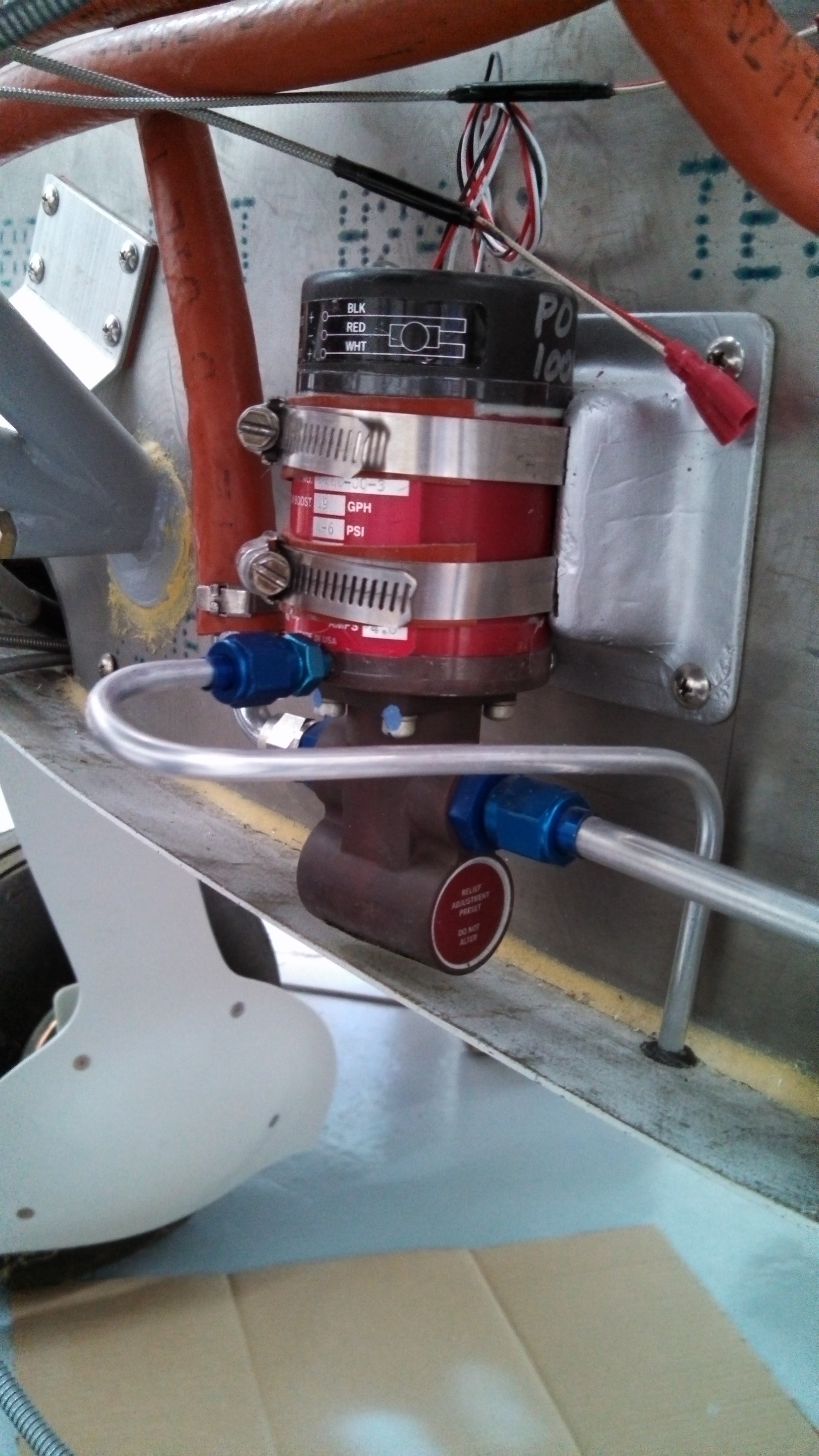
The electric fuel pump has a drain that must be routed overboard. The port is tiny. It’s a 1/16″ NPT. Since it’s a drain line with no pressure, there’s no need for high-pressure lines. I looked for a 1/16″ NPT to barb fitting but all I could find was an AN4 fitting. So I ended up with aluminum tubing. At least I won’t have to worry about dry-rot on the line. 🙂
Blog Archives
12.2.3 Mechanical Fuel Pump Drain
According to the manual, the next fuel drain line to tackle is the engine driven mechanical fuel pump. I looked and looked by couldn’t find the fitting though. I checked every book and manual I had but none showed exactly where it was. Because the fuel pump is located on the front of the engine, it’s between the engine and the firewall. I climbed all over the engine with flashlights and mirrors trying to get a better view but couldn’t find anything.
Then I took my phone and started shoving it anywhere it would fit (on the engine, thank you very much) and just kept taking pictures. That’s when I found it. On the bottom of the pump, right up against the engine and behind the fuel supply line fitting.
Now the problem is trying to get a line on the drain fitting. There was simply no way to get to fit. So I removed the supply line and I could almost get to it. Then I rotated the fuel supply fitting about an 1/8th of a turn and I was able to get the drain line on. But…
I had to rotate the supply fitting counter-clockwise. Loosening it. A definite no-no. Which means the fitting had to come out and get cleaned with a fresh layer of fuel fitting seal and then reinstalled.
So I started to unscrew the fitting. After 2 turns, it hit the oil pump housing.
The only way to remove the fitting is to remove the fuel pump. The infamous domino effect.
So off comes the fuel pump.
Here’s the pump on the bench. It’s upside down so this is looking at the bottom. Notice how the drain line is pointing directly at the supply line fitting.
And because the pump was removed, I have to replace the gasket so I had to order one of those from my A&P.
Once I got the new gasket, I reinstalled the supply fitting making sure it allowed a path for the drain line. Then reinstalled the pump and connected the supply line and feed line.
12.3.5 Propeller
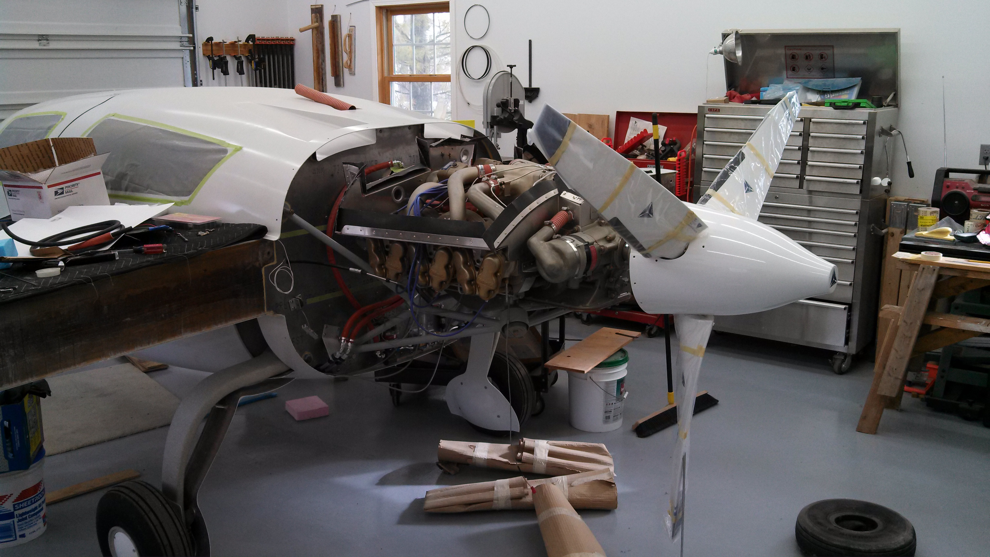
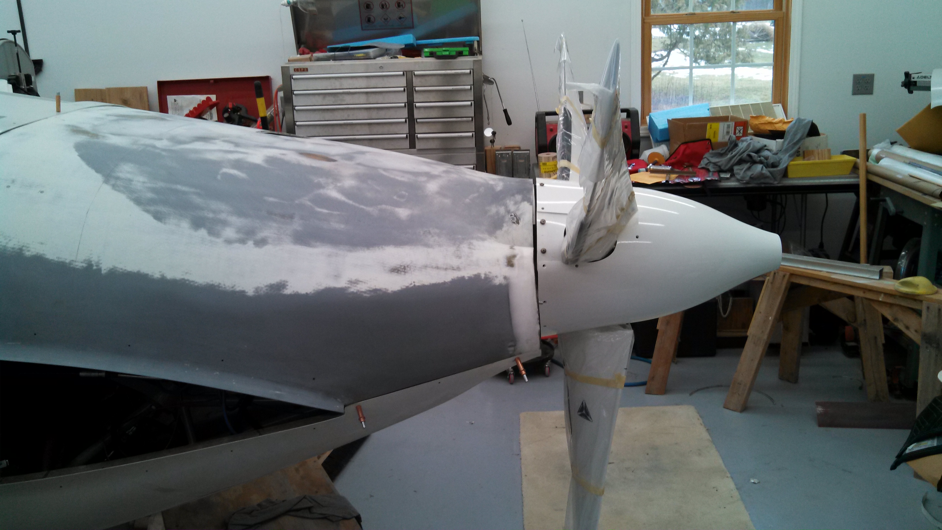
About 3 years ago, I ran across an ad for an MT Prop… at a real good price. From a distributor. The story was that the prop was ordered but due to a miscommunication, a four-blade prop was what the buyer wanted but a three-blade is what they got. Either way, the (new, never used) three-blade was up for sale. It was way too early for a prop, but I got it anyway. And for three years, it’s been sitting around, generally getting in the way. Now it’s on the engine… getting in the way.
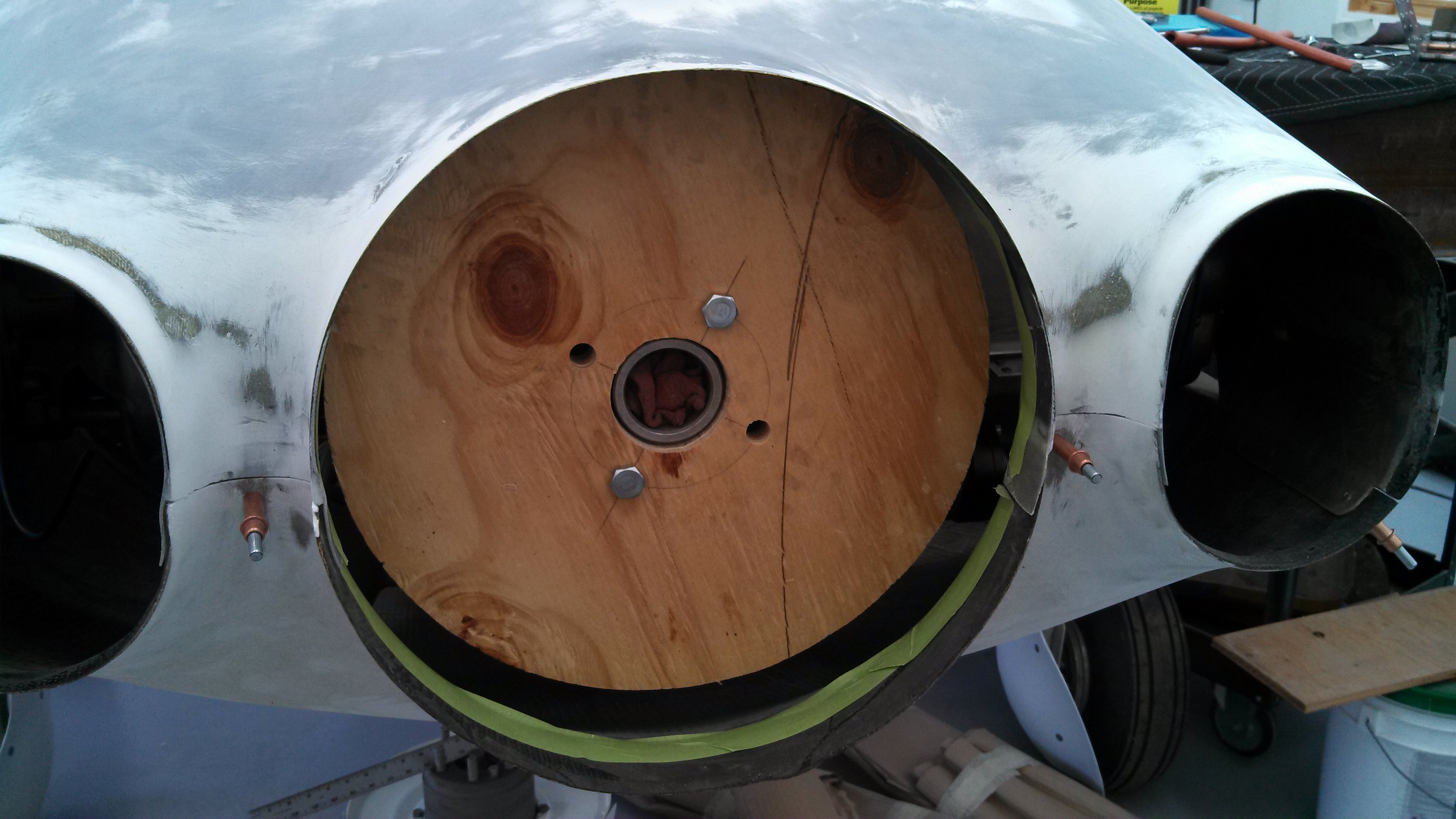
Getting the cowling on is now impossible though. The opening for the prop was never trimmed. That’s intentional so that it could be done once the prop was on and it could be trimmed as close to the prop spinner as possible. So, somehow, I have to figure out how much to cut off of the cowling without taking too much.
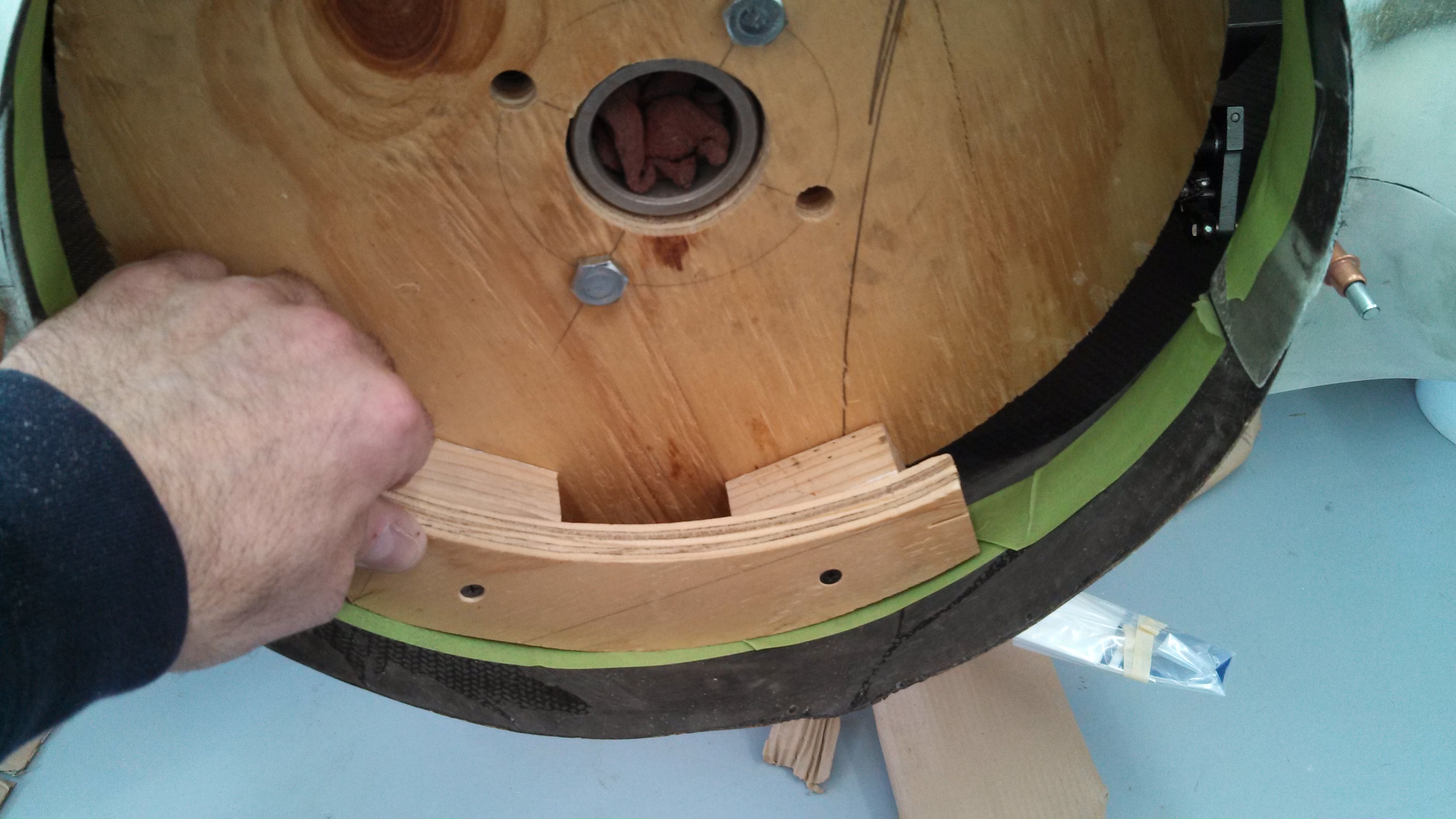
So I measured the distance from the prop flange (on the engine) to the front edge of the spinner. Then I removed the prop and bolted on a piece of plywood cut so that it just fit inside the cowling.
Then I made a spacer that would give me a dimension to where the cowling would have to be cut.
Now I just mark the cowling (black ink shows up better on green tape than black carbon fiber) where it needs to be cut.
Then cut the cowling and install.
The cowling is still very difficult to get on though as a result of the way I’m doing the cooling plenum and NACA extensions. and it’s almost impossible to assure that the NACA extensions are sealing properly on the baffles. I may have to come up with a two piece upper cowling to resolve that.
12.2.3 Fuel Pump Drain Lines
Once I got the drain on the mechanical pump I ran it over to the firewall and had it exit next to the electric fuel pump drain. The next day, I was talking to Malcolm and he mentioned that he likes to combine those two lines to avoid the “forest of drains poking out the bottom of the fuselage.”
That’s all I needed to hear. When Malcolm Collier of Hangar 18 expresses a preference about something related to building a Velocity, it’s pretty much always worth doing.
So I pulled the electric fuel pump drain line.
Spliced in a “tee” and routed the mechanical fuel pump drain line into it.
But now I’ve got a hole in the bottom of the fuselage… That I’ll use for the fuel distributor (spider) drain line.
12.2.3 Spider Drain Line
The final drain line is from the Fuel Distributor (AKA spider… you’ll see why in a minute) which sends fuel to each cylinder.
This one will be the trickiest since it will have to penetrate the plenum. First I looked through all my pictures of other IO-550N installations to see where those lines were routed.
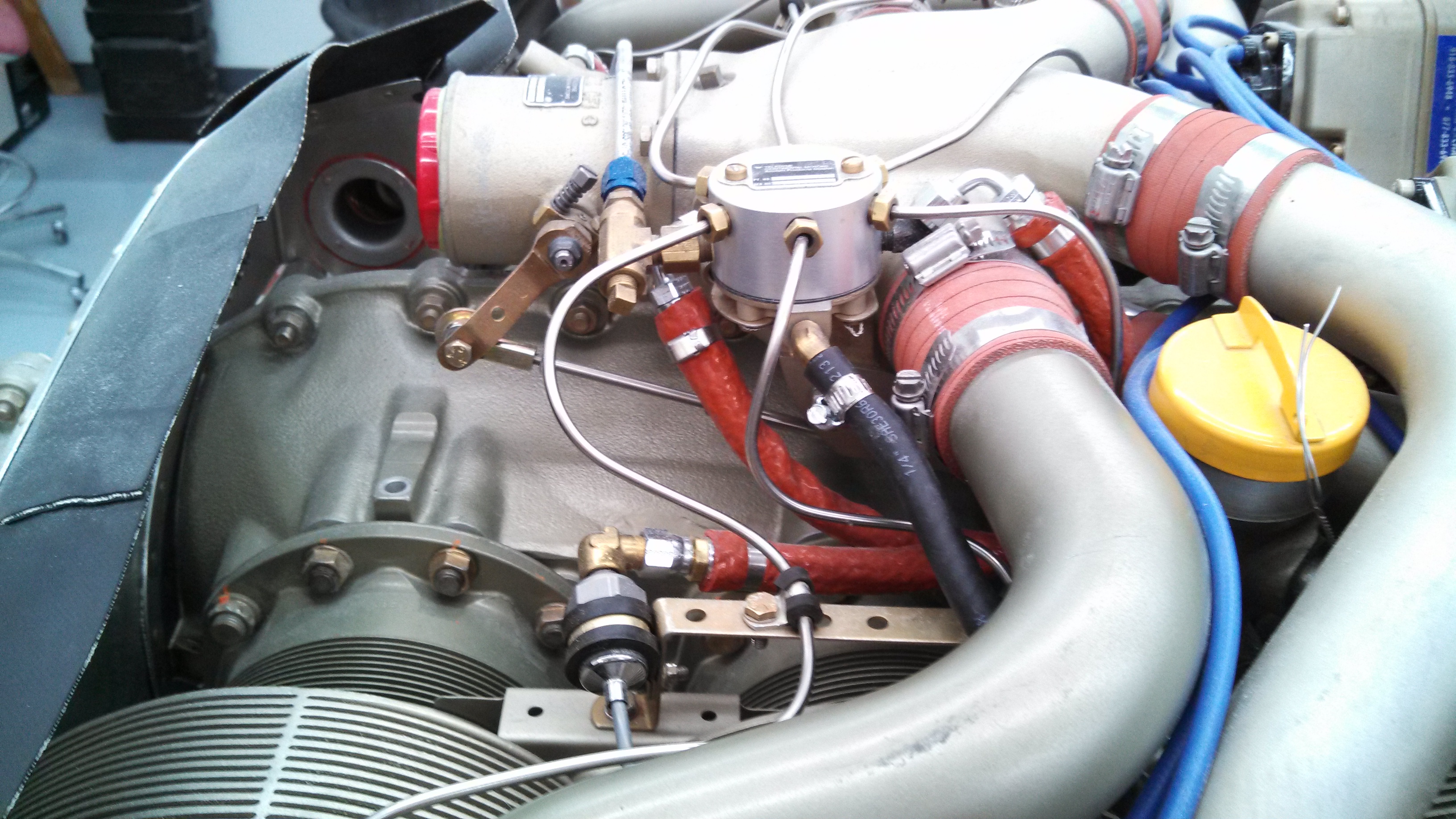
Here’s the engine as it sits now. The spider is the silver hockey puck with 6 small lines coming out (I guess it should be called an insect) which go to each cylinder. The drain fitting is on the bottom pointing towards the right.
Here’s the drain line connected.
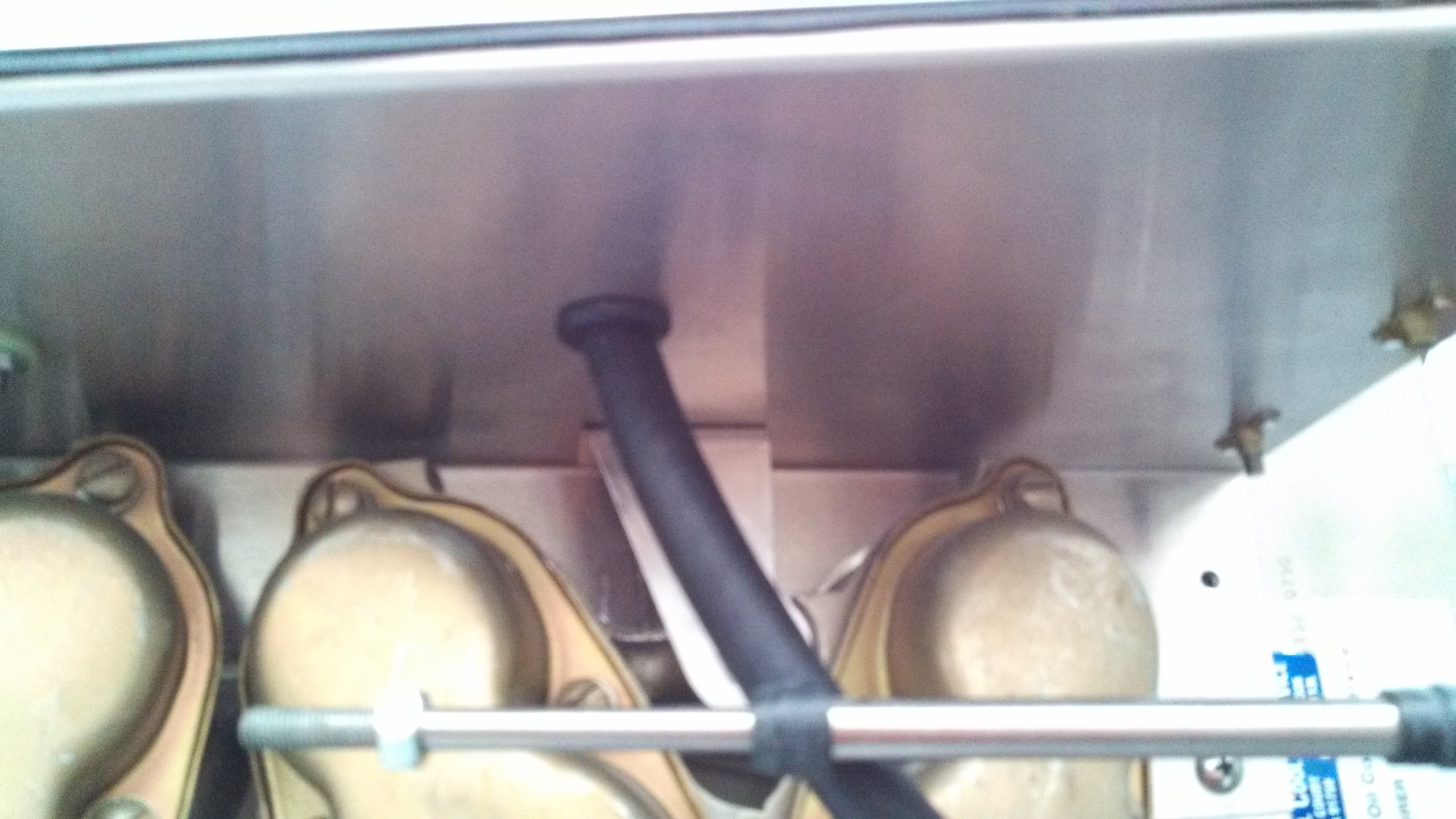
I drilled a hole in the right deck of the baffle and put a grommet in it and then ran the drain line through it.
And out the bottom.
The line is then clamped to the engine mount near the oil cooler.
Over to the firewall (I still have to put another clamp on the line at the firewall).
And out the bottom of the fuselage just to the right of the fuel pump drains.
Many builders put the flexible drain lines in firesleeve. I checked with my A&P and some references and determined that since the drain lines are non-pressurized and go overboard, it is not necessary to use firesleeve.
12.3.6 Nose Oil Cooler Control
I posted earlier about my idea to control the incoming air to the oil cooler by means of a door/flap/diverter.
My initial plan was to mount control arms to the pivots for the flappers and connect the control arms to control cables that would be accessed from the cabin. Once I started thinking about push/pull controls sticking out of the instrument panel, I changed my mind about that approach.
So I went to the local auto salvage yard and picked up a couple of heater control heads from old cars. Two levers (one for each flap) and a fan control. All I would need to do is modify it for my application.
Then I had an epiphany… While buying some switch guards from Perihelion Design (it’s where I got the dimmers for the LED cabin lighting I built), I noticed they had Servo Controllers. It occurred to me that I could control the flaps with servos. Which would mean two small knobs instead of a big honkin’ heater control box out of an old Buick. And it would be MUCH easier to route 6 small wires from the nose to the cabin rather than 2 huge, still control cables.
I swapped some emails with Eric Jones at Perihelion Design about the viability of the concept and purchased a servo controller for testing and a high-torque servo from Servo City. Initial results were very positive. Good control of the servo and decent torque.
My plan was to still attach an arm to the pivot shaft of the flaps and use linkage to connect the flap arm to the servo arm. But that quickly became cumbersome. It worked, but it wasn’t very… pretty.
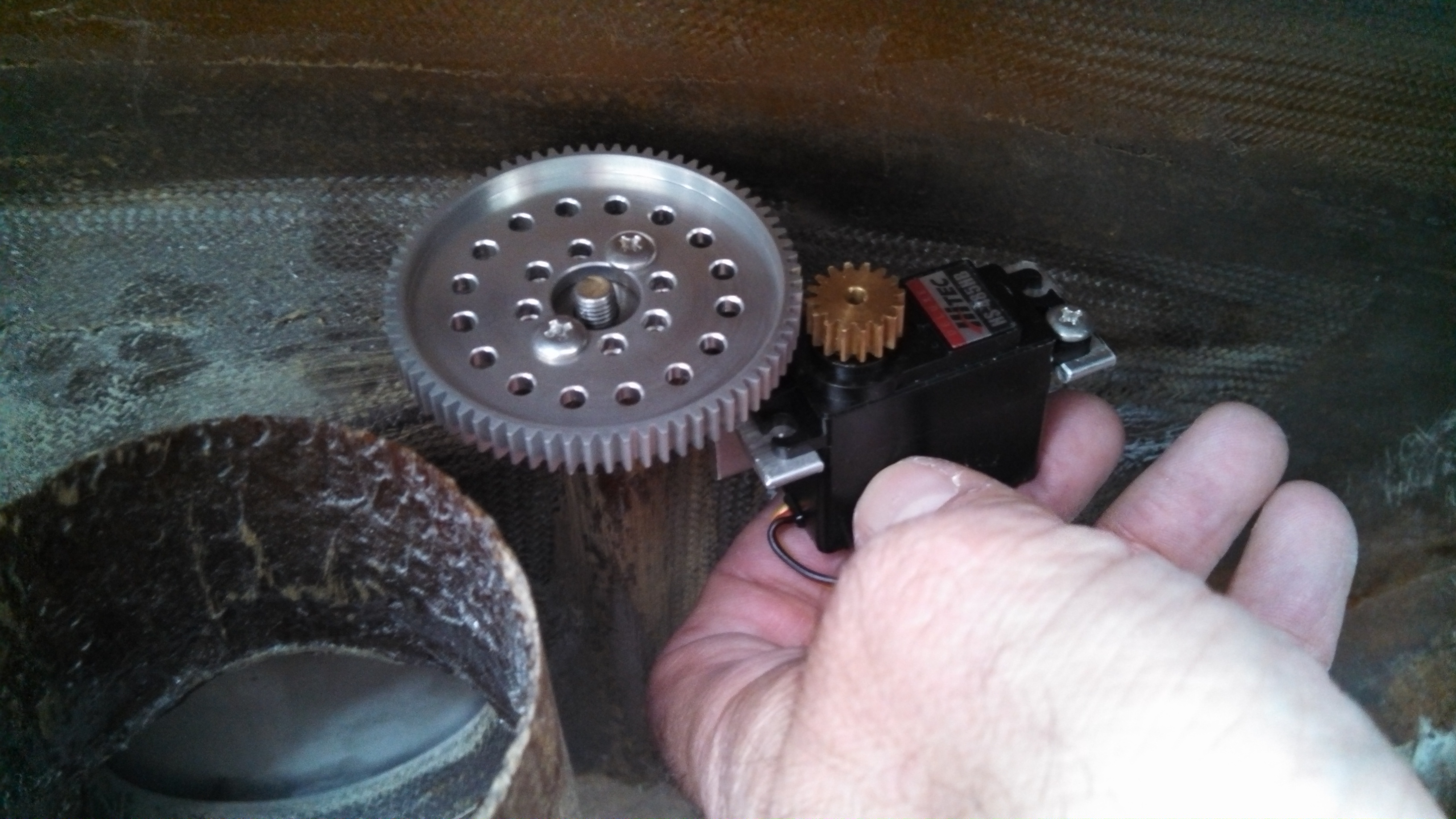
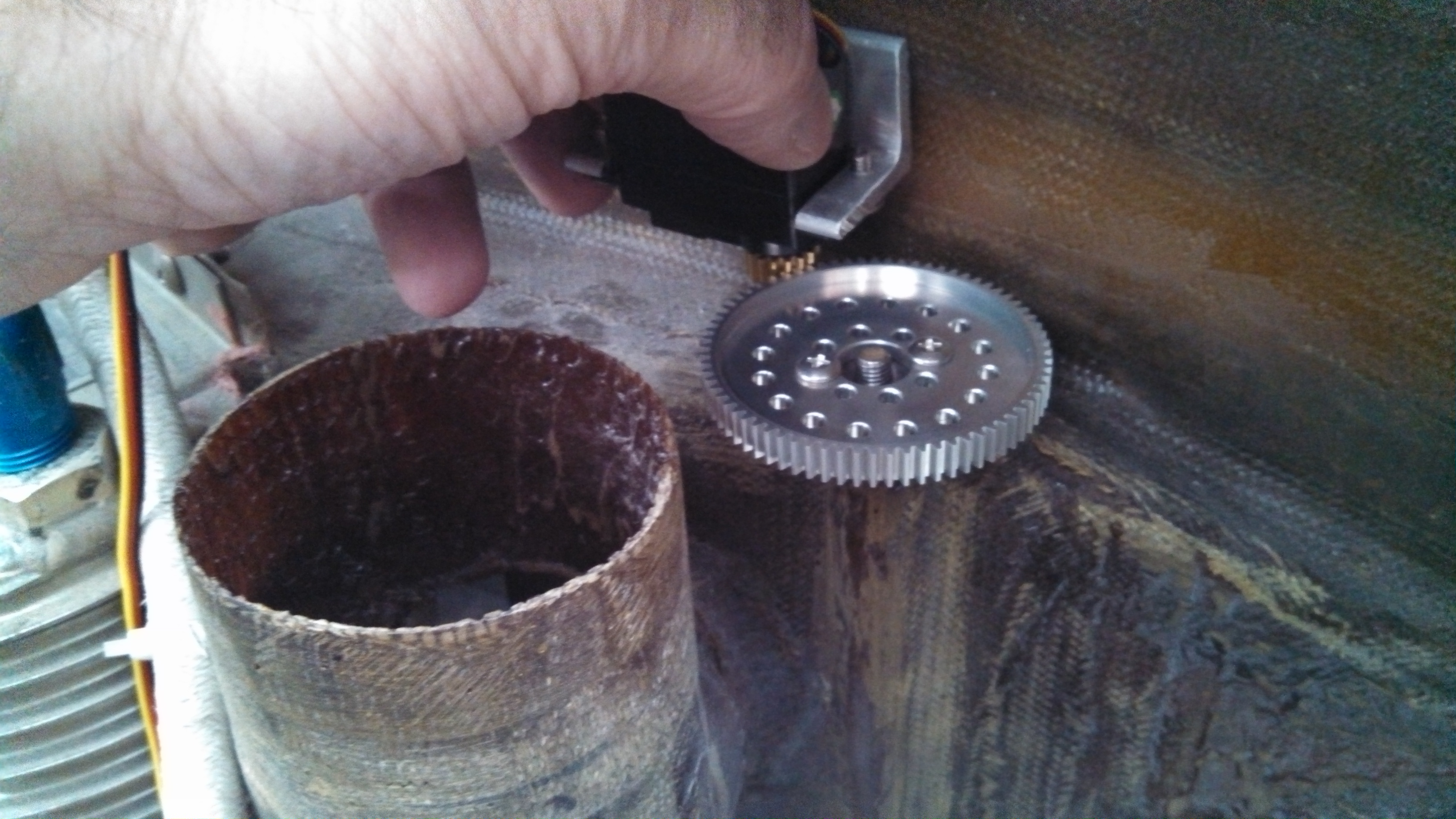
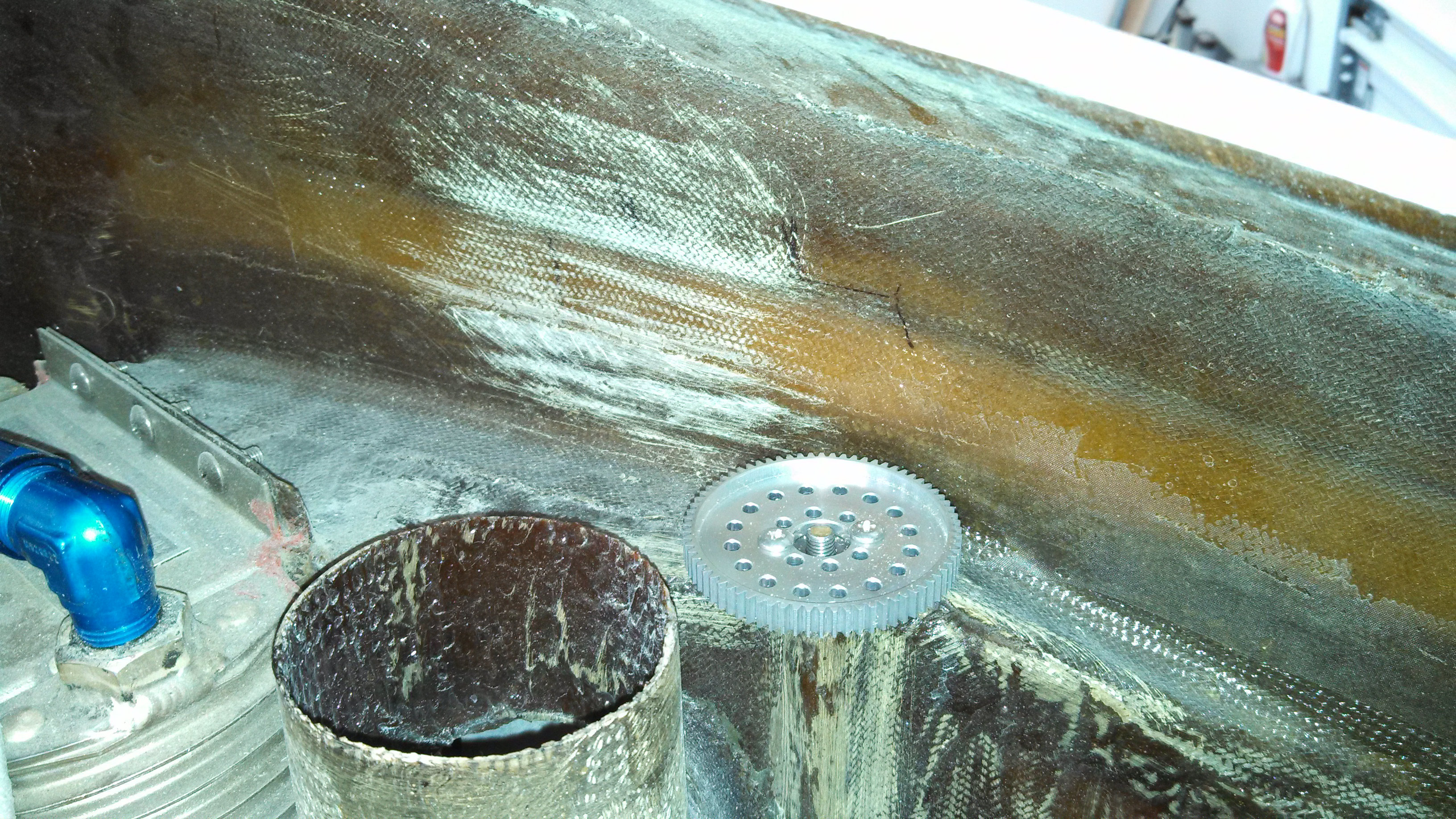
Then I decided to try geared drive. The hardest part was determining the correct gear ratio. Fortunately, my son Steve who is now working on a Physics/Electrical Engineering degree at Montana State helped out with the math on that. I picked up a large gear for the flap and a small one for the servo.
Here’s the flapper pivot with the large gear installed.
I tried a couple of different placements for the servo.
Next to the NACA duct.
But I settled on mounting it to the inside skin of the fuselage.
After determining and marking the proper location, I created and bonded a hardpoint to the inside of the fuselage.
Once that was done, it was time to install the servo and test.
There’s lots I don’t know about this endeavor. For example, I have no idea how much force will be applied to this mechanism by the incoming air in flight. I have a fairly high-torque servo (but not the highest available). One of the things I did do was with the door set to different positions, I directed air from the compressed air hose towards the NACA duct. The flap maintained position and the servo controller didn’t overheat. Now that’s not a conclusive test, but it’s the best I can do on the ground without a full scale wind tunnel.
My next task on this assembly is to do the same for the lower flap which diverts air into the cabin.
12.4 Exhaust Installation
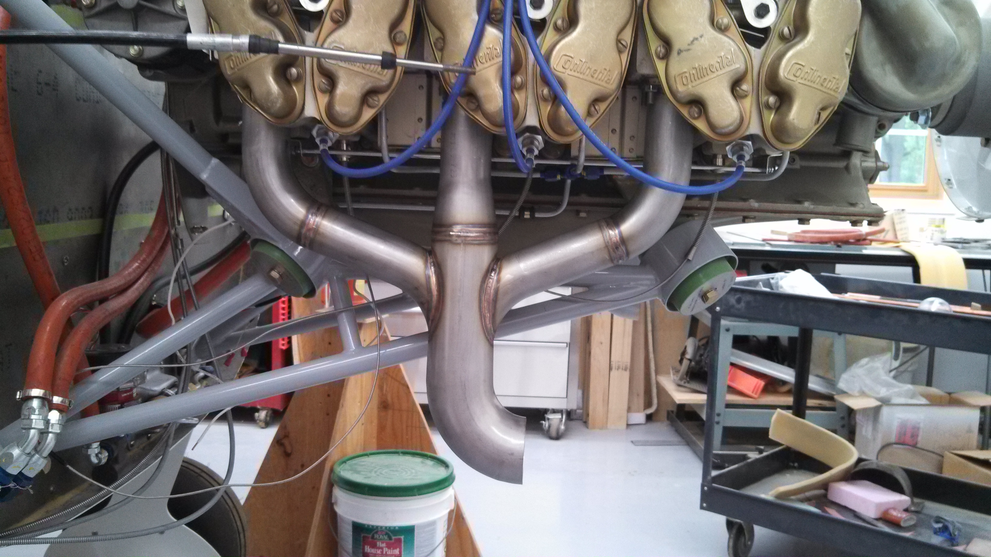
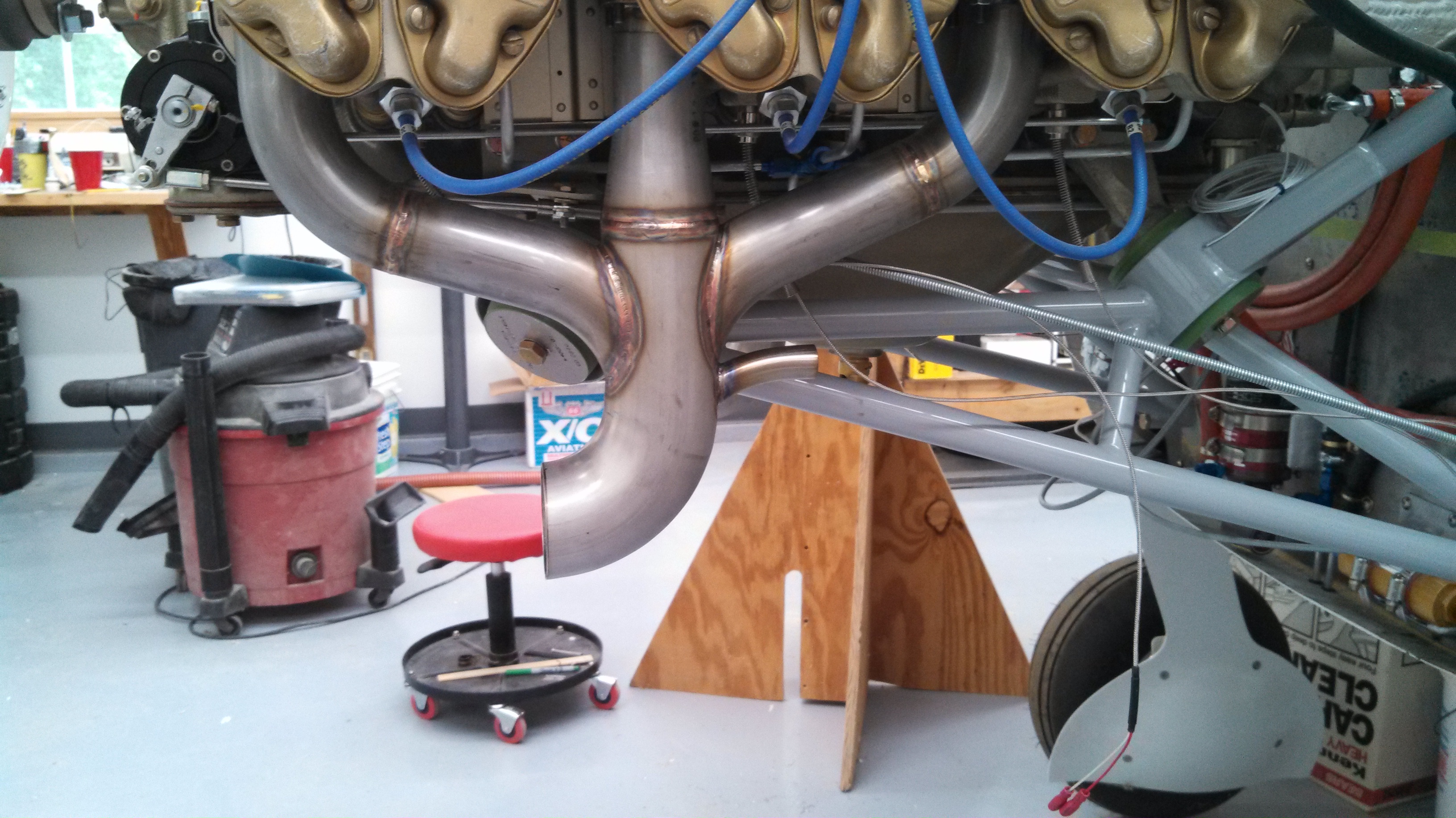
I’ve never liked the factory supplied exhaust. It amounts to 6 individual pipes (three on each side). The middle pipe on each side is straight. The forward and rear pipe on each side have a bend so that they each exit the bottom of the cowl directly adjacent the middle pipe. Not only does it result in a larger opening in the cowl, but recent flight tests by other builders have determined that the exhaust exiting perpendicular to the outside airflow generates drag which results in a loss of airspeed.
My original plan was to obtain a set a exhaust headers from an old Cirrus. Mooney or other IO550N aircraft.
I was thinking that I could reverse the direction and then they would exit the cowl pointing back. But A) I wouldn’t find any affordable headers and B) my rough calculations showed they wouldn’t inside the cowling. Having custom exhaust headers was WAY too expensive.
Then another builder (Scott Derrick) told me about Clinton Anderson at Custom Aircraft. I sent Clinton the dimensions that I wanted and he whipped up a pair of custom exhaust headers at about a quarter what I was looking at for used Cirrus headers (which would have still required significant modifications).
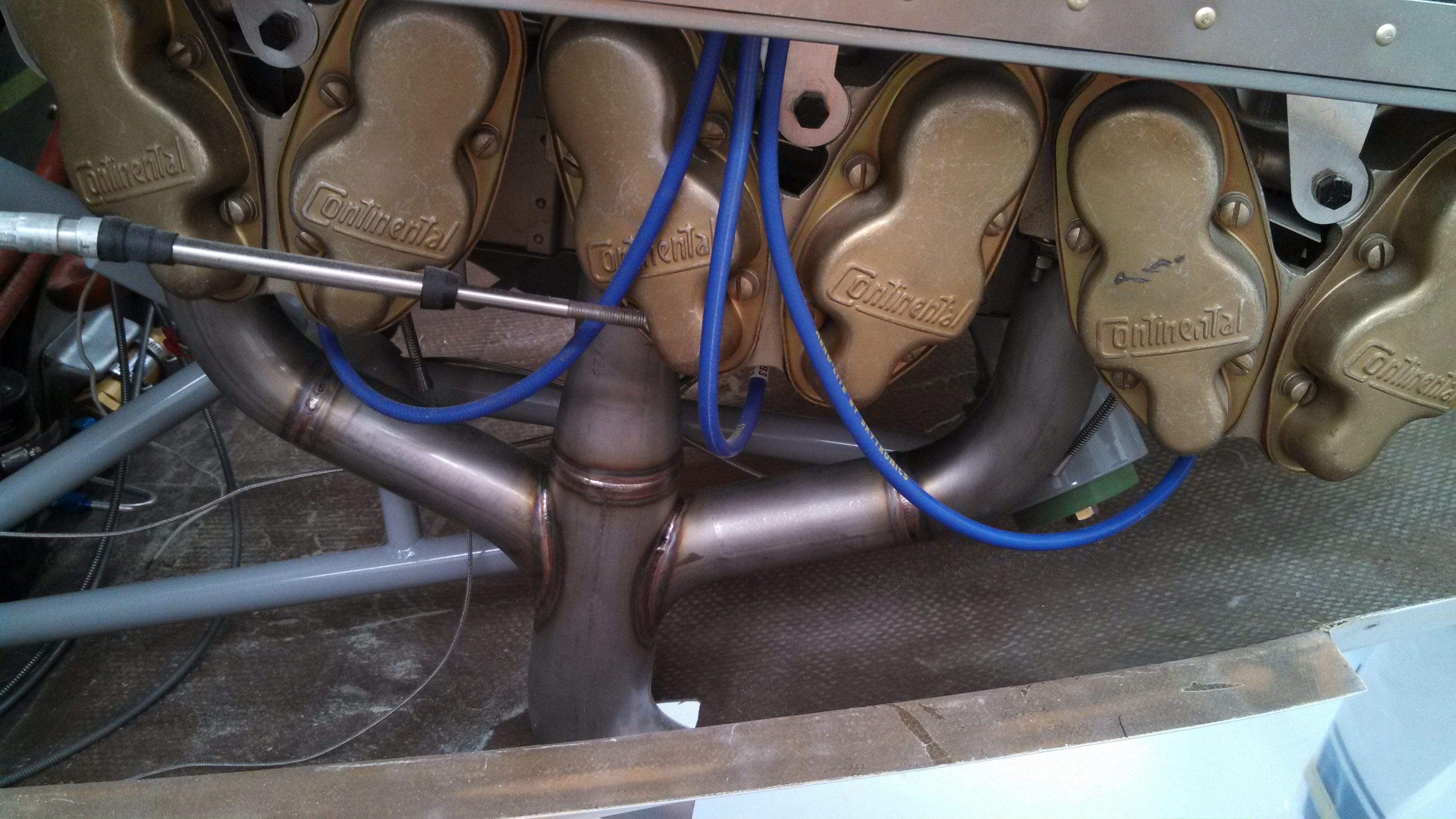
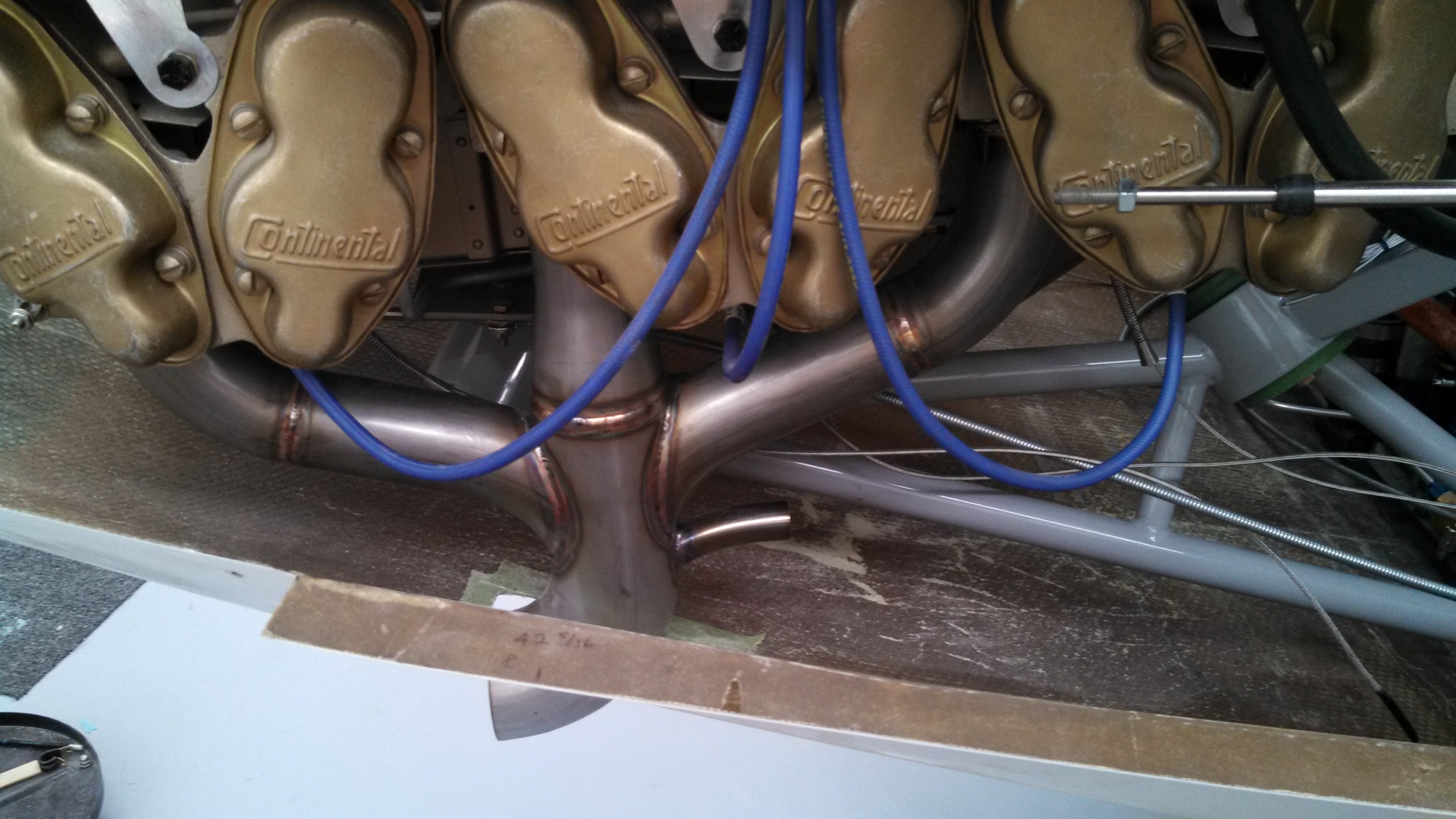
Within a week, I had my new headers (with an oil breather line plumbed too).
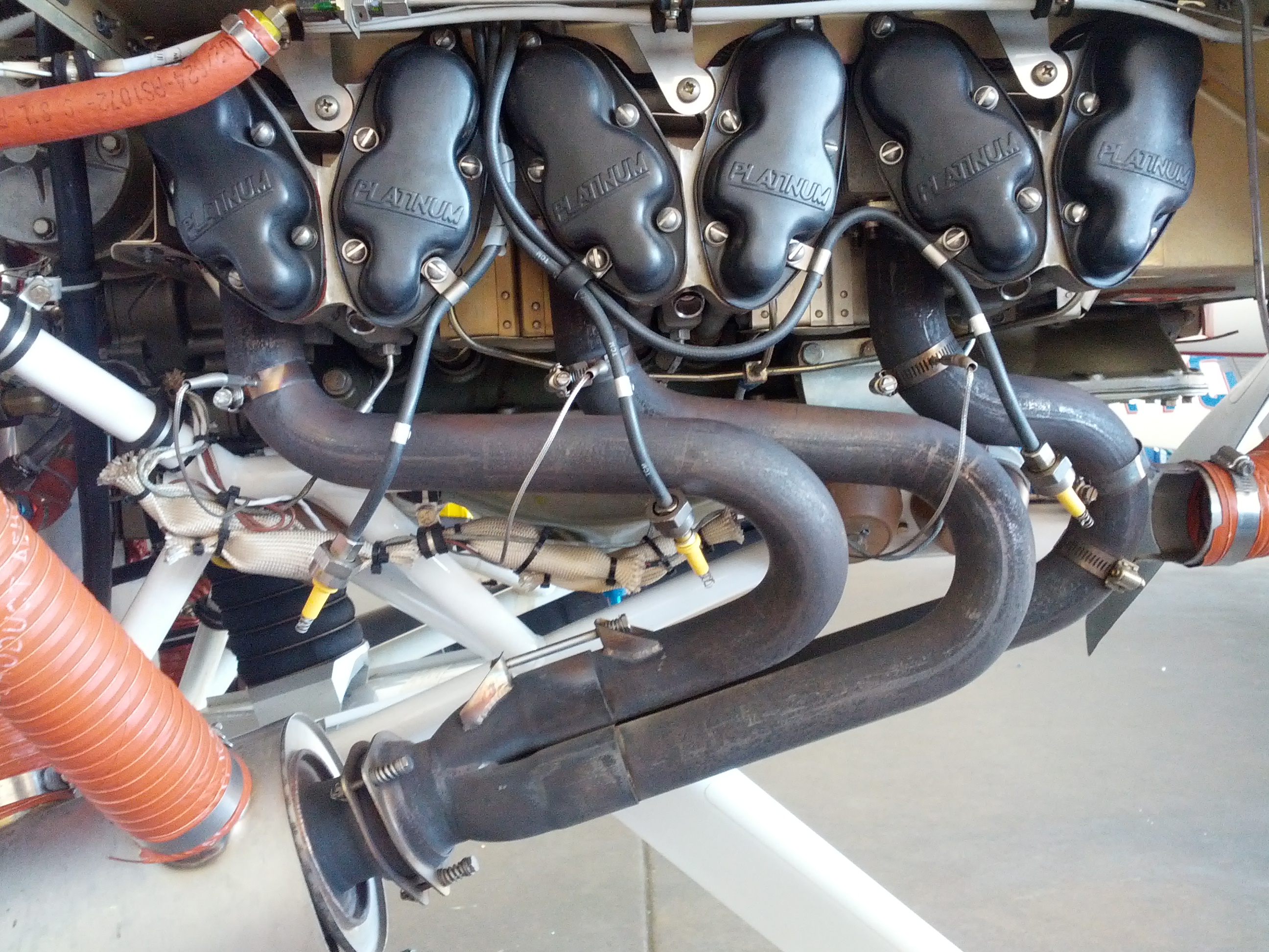
The left side header is a little longer since it sits forward of the right side. Because of the slope of the cowling, it has to be longer to exit the cowl.
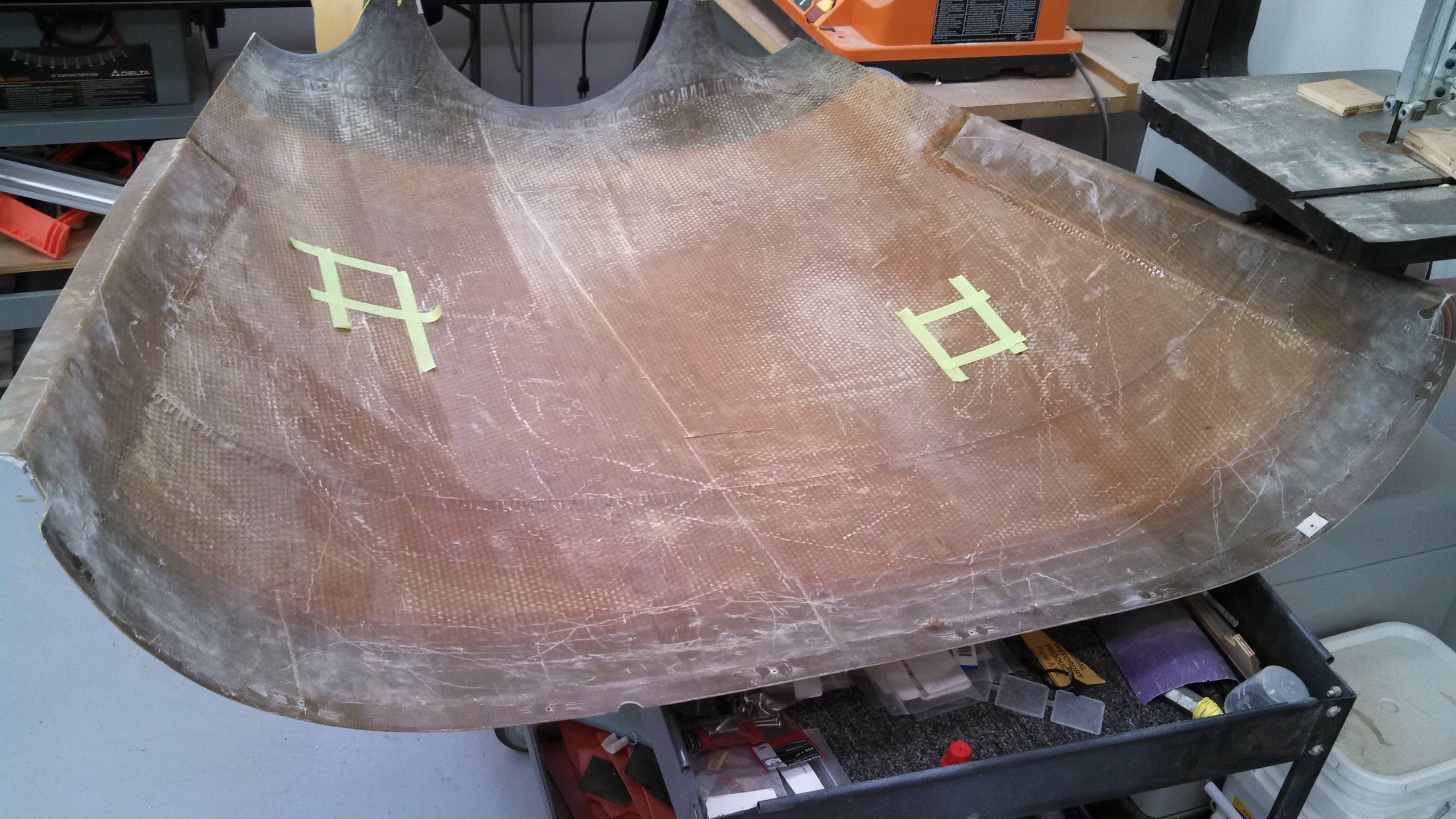
Then I installed the lower cowling and marked the location where the exhaust would be penetrating the lower cowl with green tape.
Then cut the initial holes for each side (a little smaller than necessary. After that, it was raise the cowl, see where it contacts the exhaust, trim away some of the cowling around the exhaust, raise the cowling, see where it contacts the exhaust, trim away some of the cowling around the exhaust, raise the cowling, etc., etc., etc.
Eventually, I was able to install the lower cowling with the exhaust outlet extending beyond the cowling.
Left Side
Right Side (on the inside view, you can see where the breather tube will dump into the exhaust)
My next task here will be to create a fairing in front of the exhaust to streamline the airflow around the exhaust outlet.
12.4 EGT Probe Installation
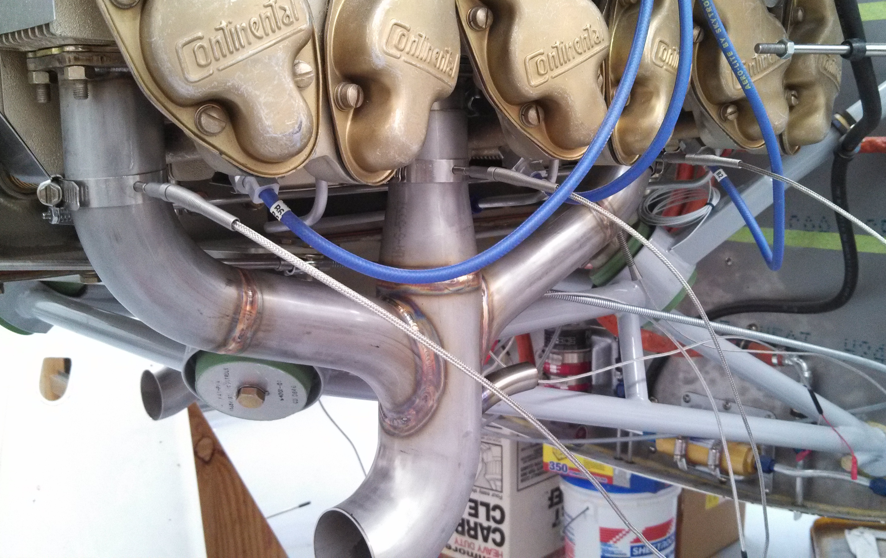
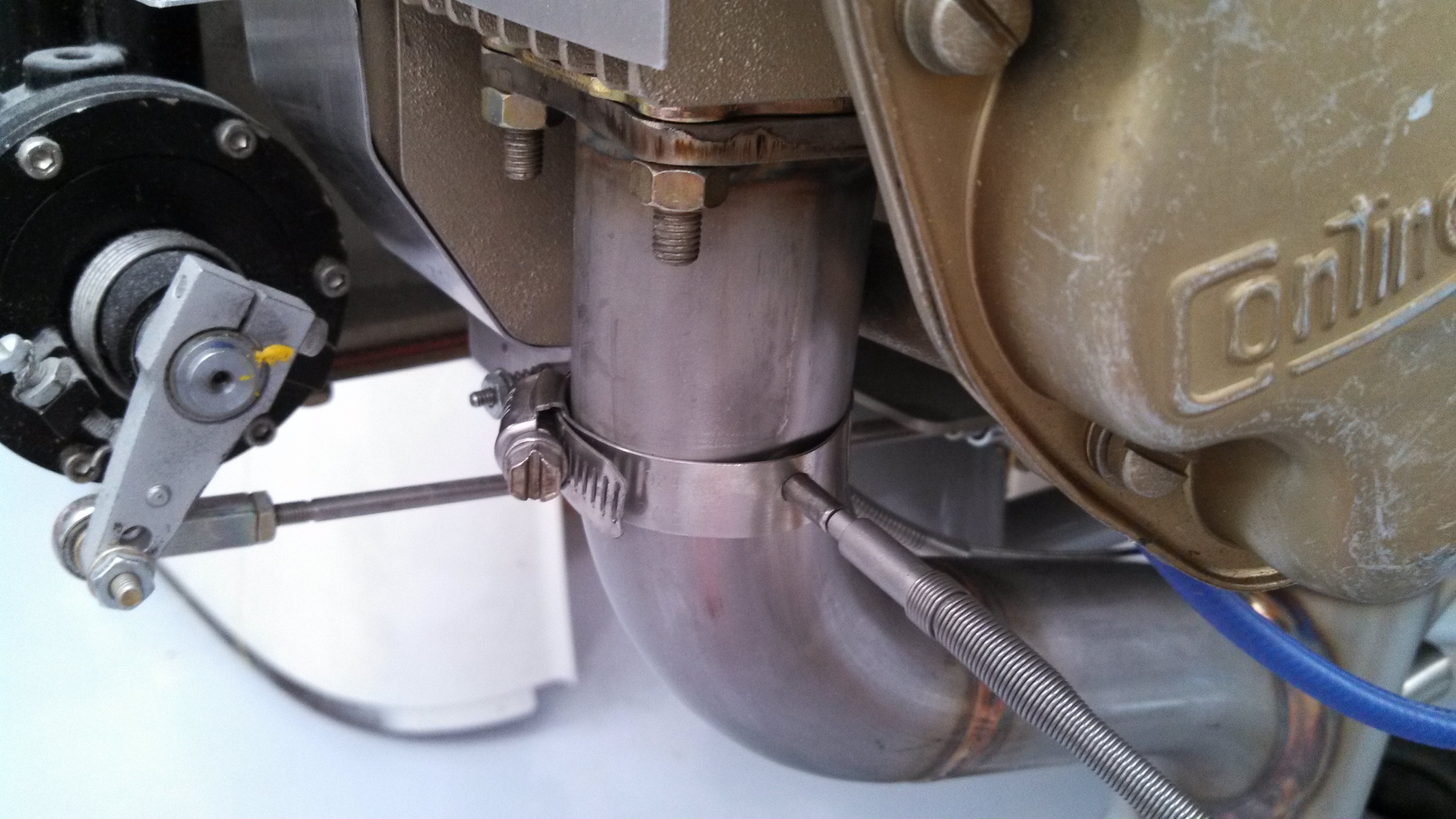
Installing the EGT (Exhaust Gas Temperature) probes is pretty straightforward. Simply measure down 2″ – 8″ from the cylinder, drill an 1/8″ hole, insert the probe and tighten the clamp.
Well, except for the center cylinder. That exhaust tube has a slip joint. And because the entire exhaust system is relatively low-profile, the probe on that cylinder was going to be where the two pieces overlapped.
So first I marked and drilled the holes (I measured down 2″). Then I removed the exhaust assembly from both sides. On the center exhaust tube, I removed the inner part and drilled that hole out to 1/4″. Then deburred all the holes, re-assembled and re-mounted the exhaust system.
Then installed the probes for each cylinder.
12.4 Oil breather line
One of the benefits of a custom exhaust is the addition of a oil breather tube port. Normally, the breather tube is plumbed to the bottom of the fuselage. The downside to this is an oily belly and another (this time a big one) tube poking out the bottom of the fuselage.
The other alternative is an air/oil separator which dumps the oil back into the engine. The engine guys I’ve talked to HATE this. They say that oil tends to be acidic not that it’s not a good idea to plumb it back into the engine.
This solution will dump the oil into the exhaust where it will be burnt (supposedly) leaving only a trace film that will just wipe away.  We’ll see about that.
One of the challenges is how to connect the breather tube to the exhaust.
At Oshkosh I ran across some “High-Temp silicon hose”. I picked up a piece not knowing if it would even fit. To my surprise, not only is it the correct length, but it’s also the correct diameter.
Even though it’s “high-temp”, I decided to create a shield. The tube itself shouldn’t get too hot for this hose, but I decided to go belt and suspenders. So I got some of the leftover titanium and built a little shield.
It might not even be necessary, but it can’t hurt.
12.2.4 Oil Pressure Sensor (remediation)
Many builders create a manifold that the various pressure sensors mount to. I created one of these but abandoned it due to space considerations. One of the things the manifold does provide is a convenient ground connection.
My attempt at accommodating this was to attach an aluminum tab to the sensor. But I just don’t like it.
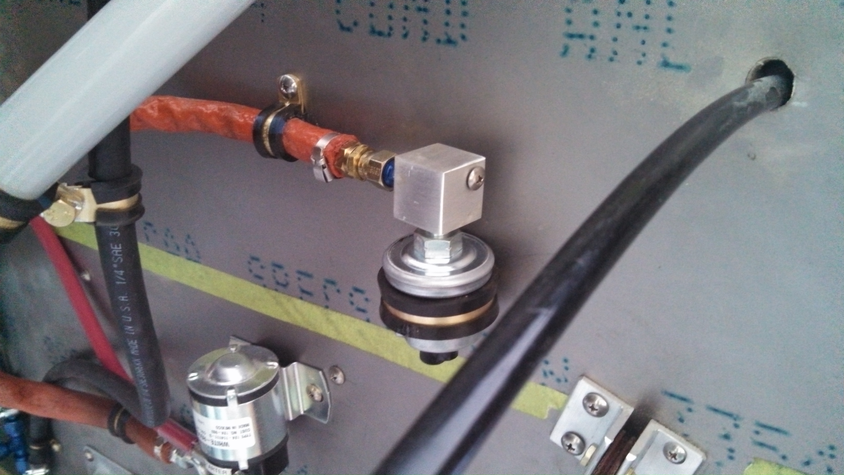
So I got a piece of 1″ stock, drilled and tapped it for the NPT fittings and an 8-32 screw for a ground connection.