
- 7.2 Nose Gear Installation (Door mechanism)
- 7.8.2 Landing Gear Plumbing – Dump Valve
- 7.8.2 Landing Gear Plumbing – Bulkhead fittings
- 7.8.2 Landing Gear Plumbing – Dump Valve
- 7.8.2 Landing Gear Plumbing.
- 7.8.2 Landing Gear Plumbing
- 7.8.4 Landing Gear Electrical
- 7.0 Landing Gear Retract Test
- 7.0 Landing Gear Retract Test II
- 7.7.3 Main Gear Doors
- 7.7.2 Parking Brake
- 7.8.4 – Landing Gear Electrical
- 7.8.4 Main gear microswitch wire routing
- 7.8.4 Main Gear Micro Switches
- 7.8.4 Nose Gear Up Microswitch mount
- 7.6.3 / 7.8.1 Install Landing Gear Hydraulic Cylinders
- 7.1 Nose Gear Door Installation
- 7.1 Nose Gear Door Installation
- 7.6.1 Main Gear Pulley Installation
- 7.6.1 Main Gear Pulley Installation
- 7.2.1 Nose Gear Installation
- 7.2.1 Nose Gear Installation
- 7.4.1 Gear Leg Cut Out
- 7.2.5 Nose Gear Guides
- 7.8.1 Hydraulic Power Pack Installation
- 7.4.3 Transverse Bulkhead Installation
- 7.5 Main Gear Bushings
- 7.4.3 Transverse Bulkhead Installation
- 7.6.2 Main Gear Sockets
- 7.7.1 Main Gear Leg UpStops
- 7.7.3 Main Gear Doors
- 7.7.3 Main Gear Doors
- 7.7.1 Main Gear Legs (Painting)
- 7.2 Nose Gear Door Mechanism
- 7.3 Nose Gear Door Mechanism
- 11.1.4 Lower Cowling to Wing Flanges
- Nose gear spring replacement
- 7.2 – Nose Gear Door Actuator Replacement
- 7-99 Sealing the Nose Landing Gear
The upper part of the gear legs (which are inside the fuselage) are supported fore and aft by sockets that they are held captive when the gear is extended. These sockets are made to be perfect fit to the upper gear leg by wrapping the area with duct tape and then applying 3 layers of triax.
Duct tape on the upper gear leg.

Three layer of triax.
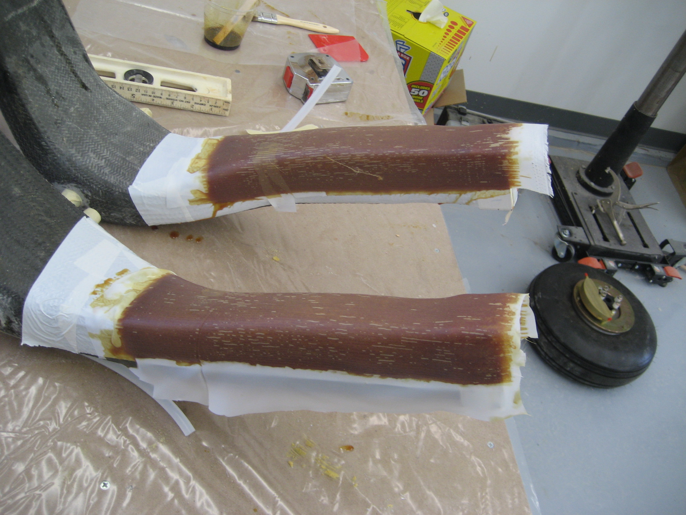
Once cured, they are removed and then trimmed to the rough dimensions.
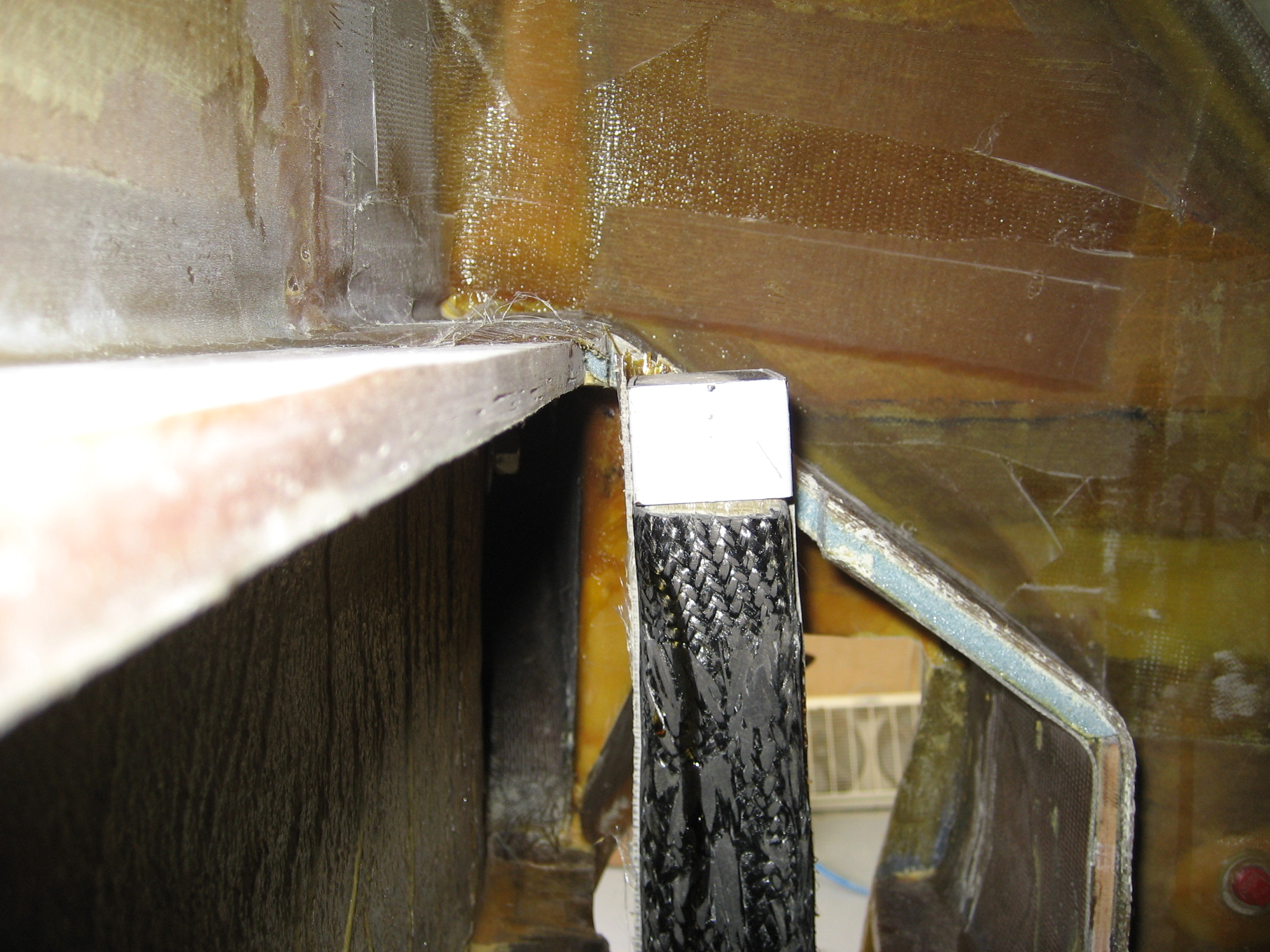
Currently, the only permanent aspects of the main landing gear are the pivot points which the gear legs pivot at and the over-center linkage which defines the distance between the tops of the two gear legs. So right now the over-center link can move left to right (which in turn lowers one leg while raising the other) about 1 inch. Once the sockets are in there will be no movement at all. So getting that position exact is critical.
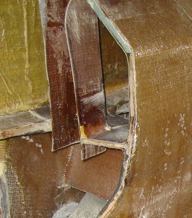
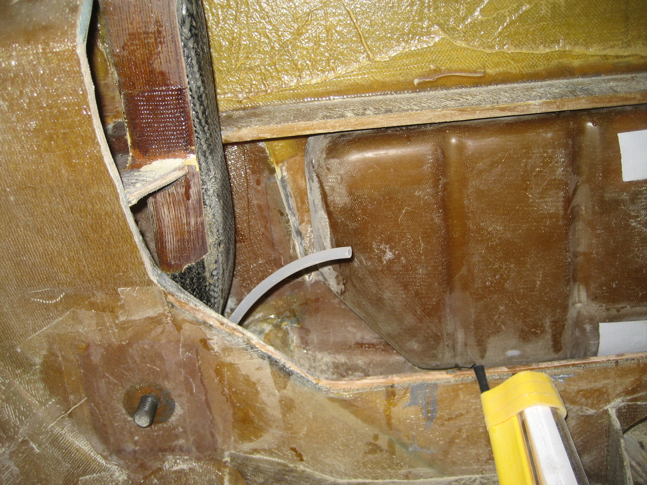
This is the left upper gear leg and socket where it intersects the slant bulkhead. I’ve already created a notch in the bulkhead to accept the gear leg and socket.

Now the task is getting the two legs perfectly level. So here’s how I did it.
I raised and leveled the airplane, removed the axles from each leg. Then I leveled my laser level and shot the beam through the lower/rear hole in the gear leg.
Laser is level.

Shooting from the outside at the right gear leg right through the center of the hole.
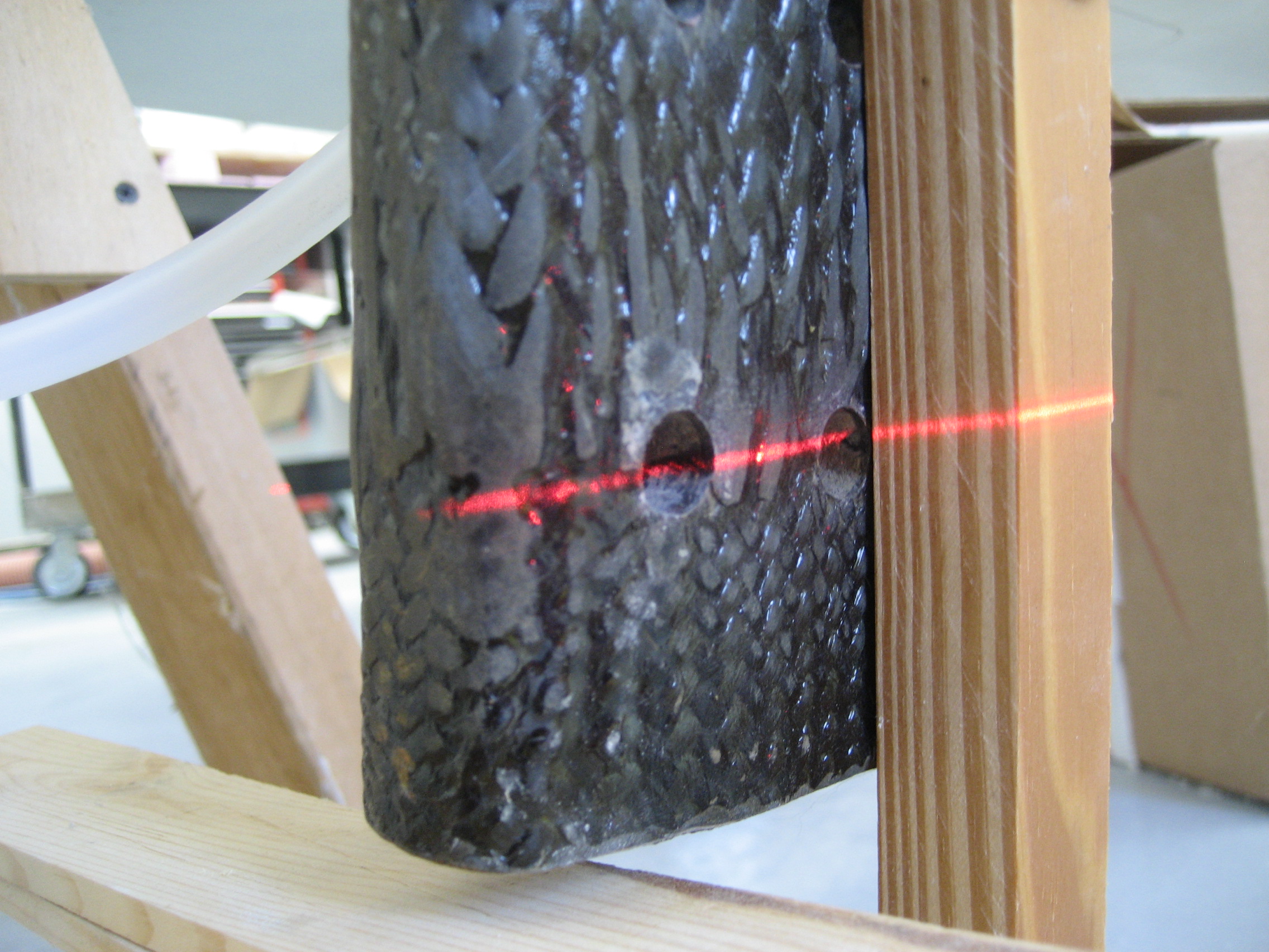
And it’s a little low on the left side.

Moving the gear legs a slight amount (lowering the right leg raises the left) and the beam is centered on both holes. Once I determined the method worked, I raised the gear and prepped the transverse and slant bulkheads for bonding in the sockets.

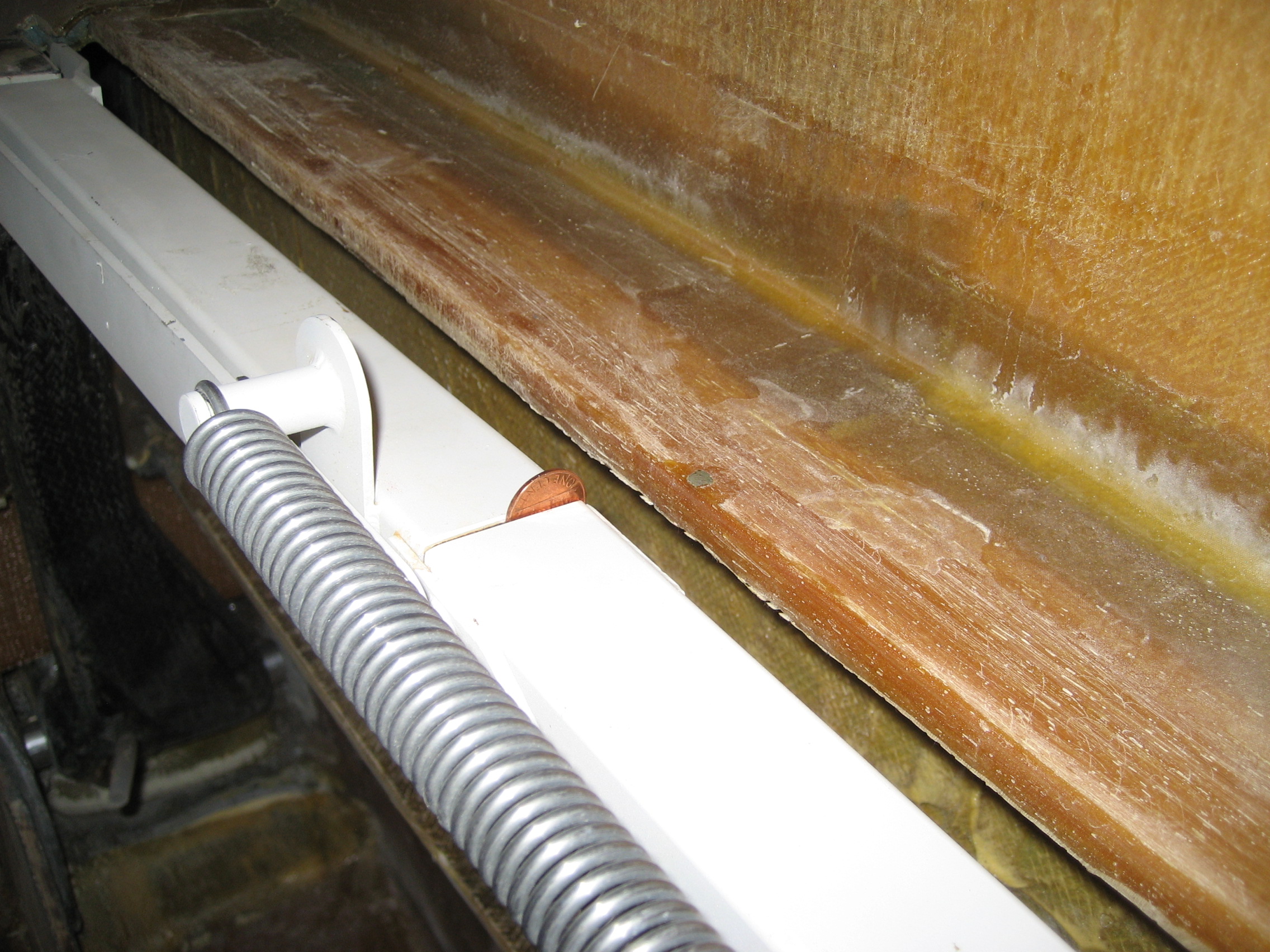
Then the gear sockets are fitted on the gear legs and lowered gear with a penny is inserted into the over-center link. This keeps the upper arms spread slightly beyond where they are when the gear is down. This will prevent the gear from binding in the sockets when it’s lowered.
Next I determined the correct position of the gear legs using the laser level and secured the position. Then I used structural adhesive/cabo to bond the sockets to the bulkheads. Once the adhesive has cured, the sockets to bulkhead is reinforced with a radius and BID on all sides.
I will do the layups on the bottom when I flip the plane over.