14.2.2 Priming

This entry is part 8 of 38 in the series 14 - Final Assembly / FInishing

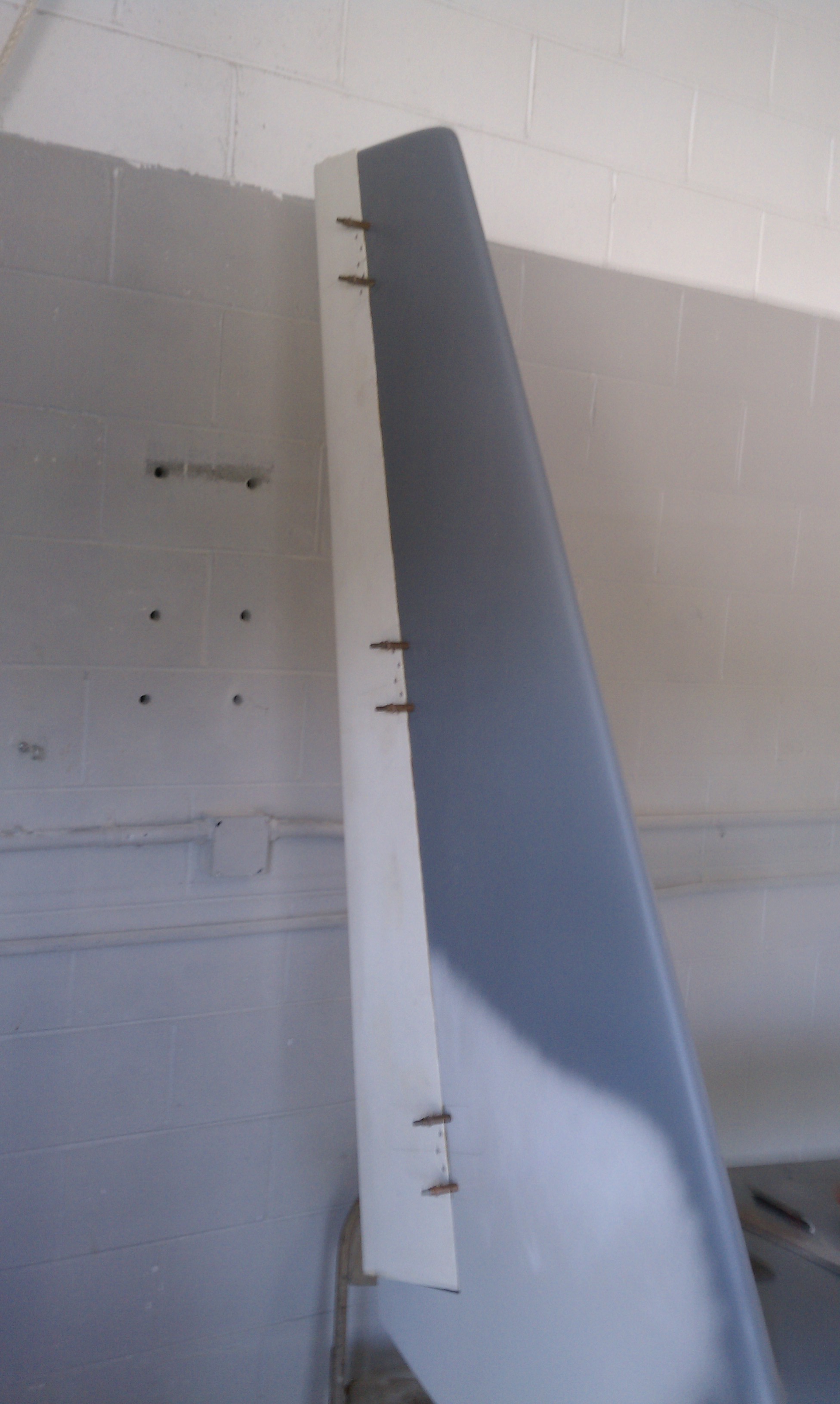
Now it’s time to get ready for the first coat of primer. Like on the bottom, we’ll start with the gray primer. There are a couple of places that we simply can’t figure out if we have a low spot or an area surrounded by some high spots. Once the gray primer is one, then we will (hopefully) be able to figure it all out.

Here’s the “before” shot with the (top) in full “spotted dog” mode.

Since Malcolm has only one respirator, he did just about all the spraying. I mixed when he ran low on primer.

Spraying primer.

Almost done

The “after” shot. (we put the canard on hatch covers on just because)

Malcolm suggested painting a mouth with teeth under the nose since it looks like a shark.

And here’s another reason to prime at this point. The plane is COVERED with pinholes. They’re almost impossible to see until the surface is in a single uniform color. Once it is, they are VERY easy to see.

99 Malcolm Collier, Tank Builder

This entry is part 3 of 10 in the series 99 - Non-Build Topic

Here’s an interesting tidbit. What does Malcolm do when he’s not building airplanes?

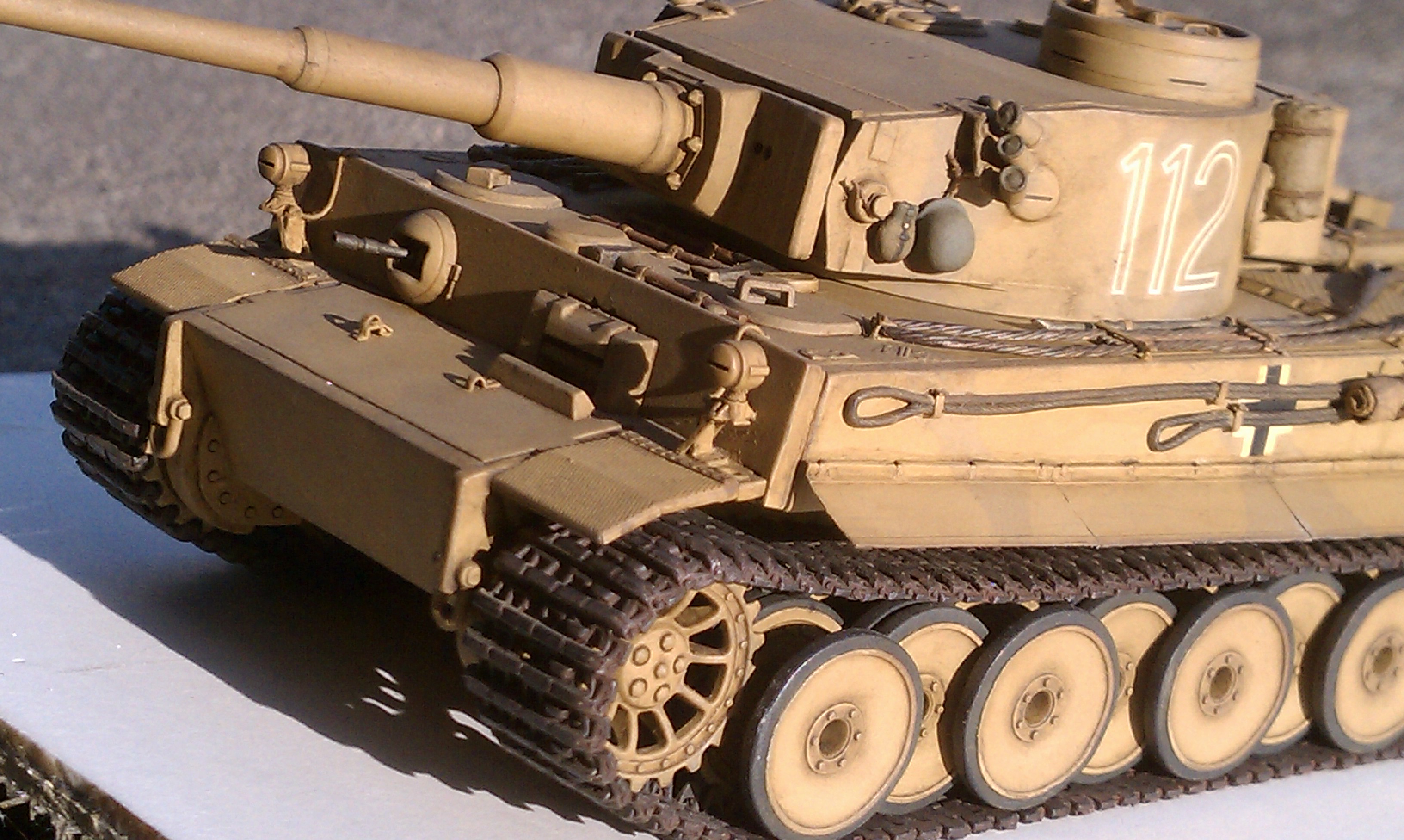
He builds scale WWII tanks (insert original Flight of the Phoenix movie reference here).

Here’s one of his masterpieces.


See the tow cables on the side of the tank? The little helmet on the side of the turret? Oh yeah… and the treads; they actually move.

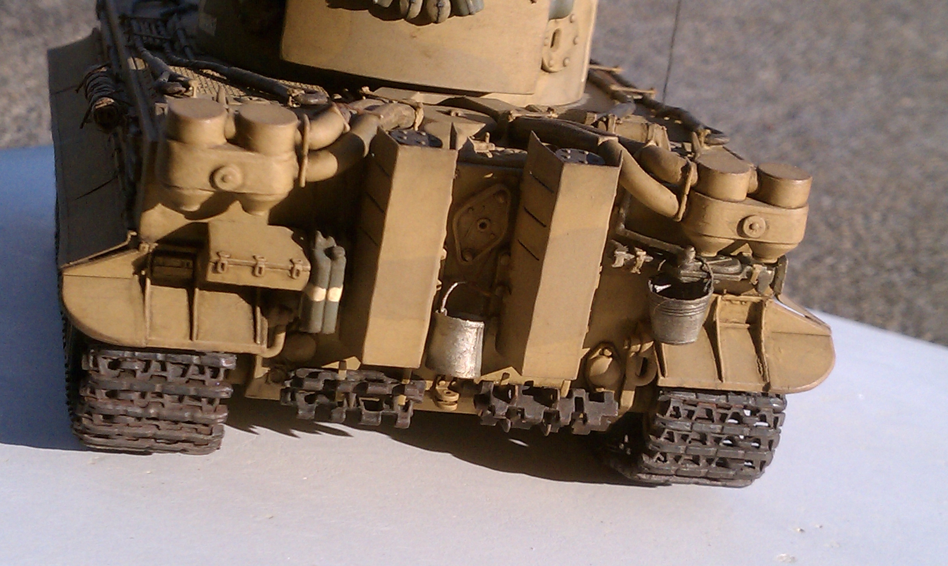
The back of the tank.

How about that little tiny bucket? It’s hand made… Out of metal. I’ll bet it actually holds water.

Back of the turret.

Check out those canteens. And this tank is about SIX INCHES LONG. Many of the parts on this tank are fabricated from scratch in Malcolm’s model building facility. He uses pictures of actual tanks, maintenance manuals, construction drawings (the original 70 year old documents), etc. when building these tanks. The detail is almost scary. Most of the times when he shows me what he’s working on, I can barely see it. He makes bolt heads that are only a couple thousands of an inch across.

2.8.3 Rudder Installation

This entry is part 4 of 8 in the series 02 - Wing / Winglets

The procedure for mounting the rudders is similar to the ailerons… Just backwards. First the bottom of the rudders are squared up and the fit is verified. Then the hinges are mounted to the rudders with structural epoxy and countersunk rivets.

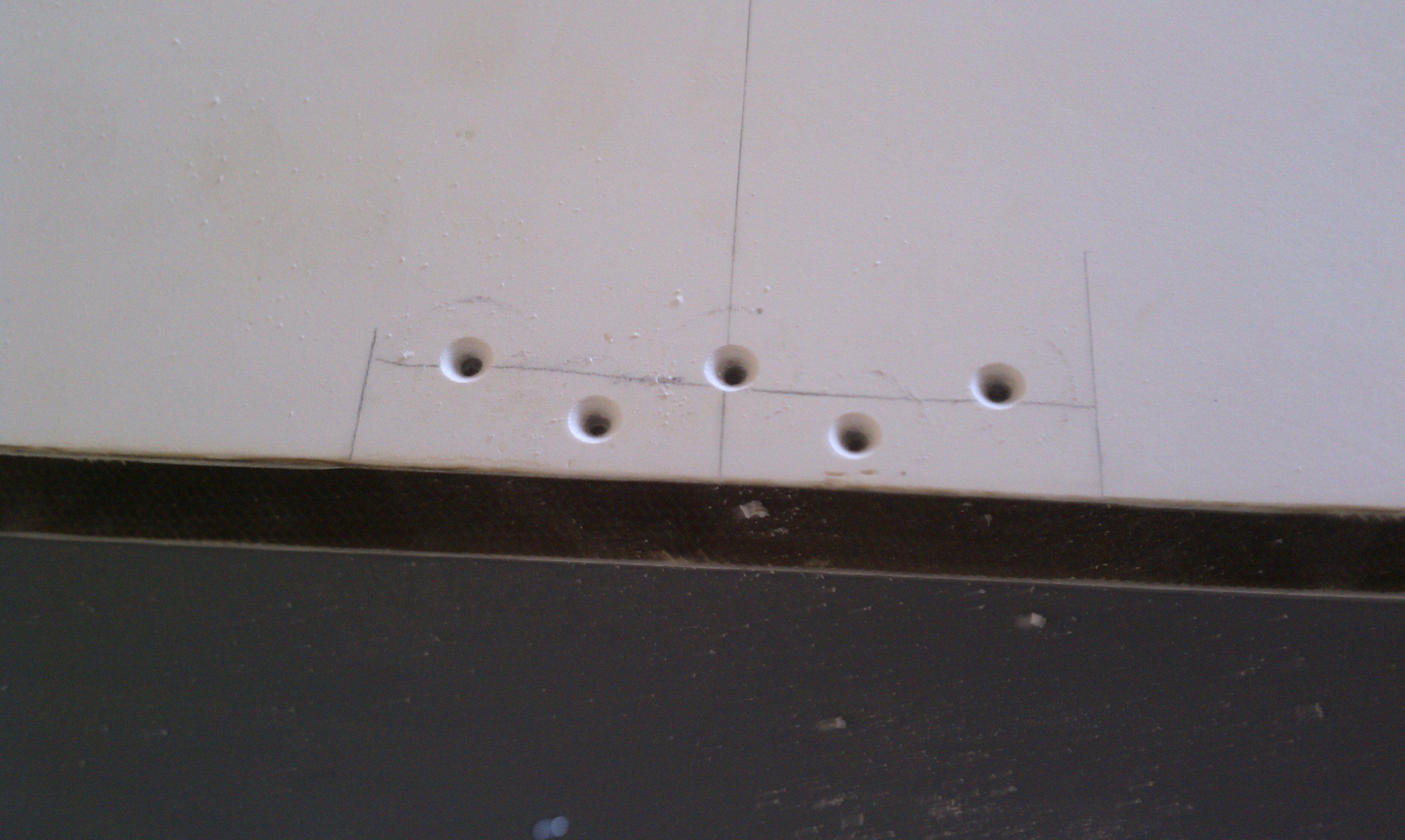
One of the hinge pads drilled and countersunk ready for the hinge.

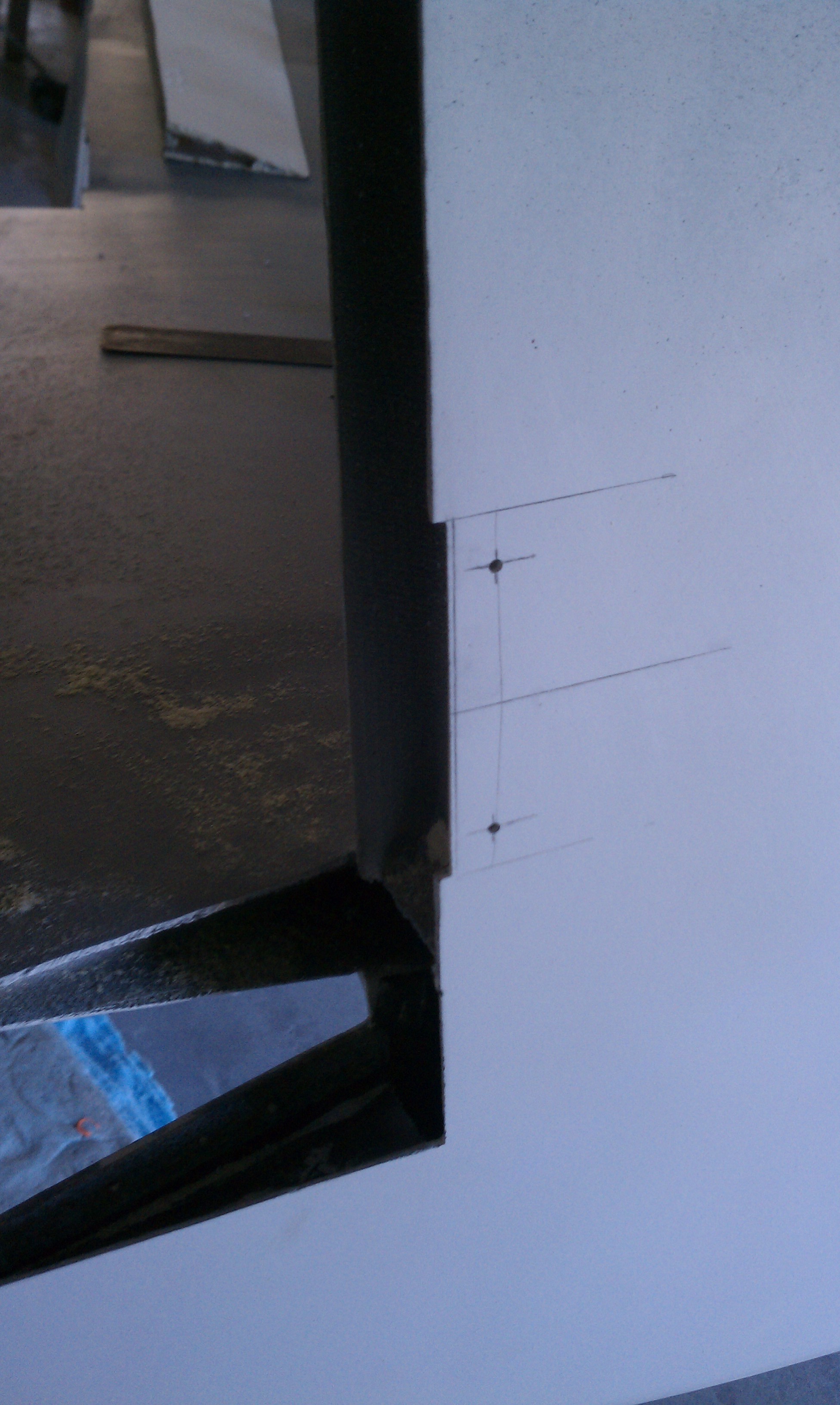
Next two holes are drilled in the winglet.

Then Malcolm held the hinge in place and with a thin piece of steel, pressed hinge against the inside of the winglet. While he was doing that, I drilled through the hole in the winglet into the hinge. Once the hole was drilled, a cleco held it in position and a the second hole was drilled.

All three hinges drilled with two holes each.

Close up.

A third hole is then drilled in each hinge.

99 MBA Kris

This entry is part 2 of 10 in the series 99 - Non-Build Topic

In the middle of all this I had to teach a Nexus 7000 class in New Jersey at the end of April. Ann was in New York at the same time. When she was done with her business on the 28th, so she caught a train to New Jersey. After the class was over on April 29 we drove down to Wilmington, DE to attend my neice’s graduation. She was receiving her MBA that she obtained in 18 months on her own while working two jobs. Beat that!!!

Kris.

Kris and her proud papa.

The following Saturday, I drove Ann to Philly to catch a flight home. Then I took Kris to lunch and then we went for a sightseeing flight over Delaware and New Jersey.

Kris at the controls.

She’s got a real good touch on the controls. Most people over-control but she seems to have a knack for it.

2.8.5 Rudder Return Spring

This entry is part 2 of 8 in the series 02 - Wing / Winglets

These rudders aren’t really rudders in the traditional sense. They’re actually vertically oriented ailerons that can only be deflected in one direction. End result is that to get them back in the neutral position, a spring is used. The spring is embedded in the winglet. A one inch diameter hole is drilled into the back of the winglet five inches deep. To keep the hole from damaging the navigation antenna, it’s important to keep the drill laterally aligned. It’s also important to keep the drill aligned vertically so that it’s perpendicular to the leading edge of the rudder.

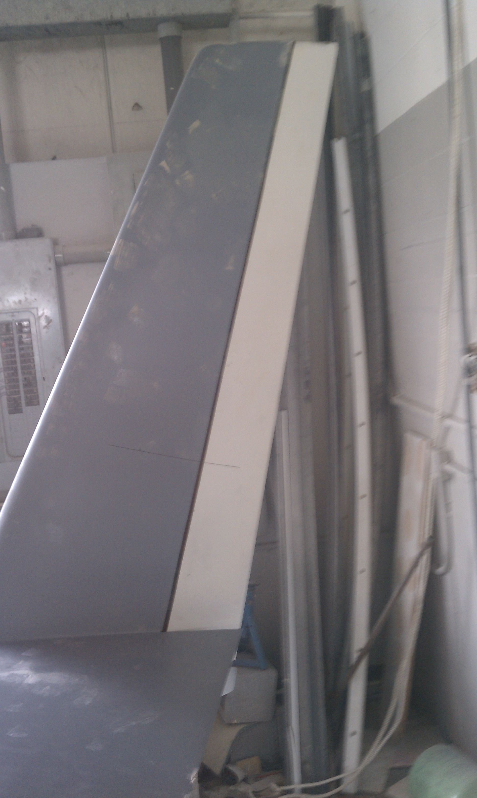
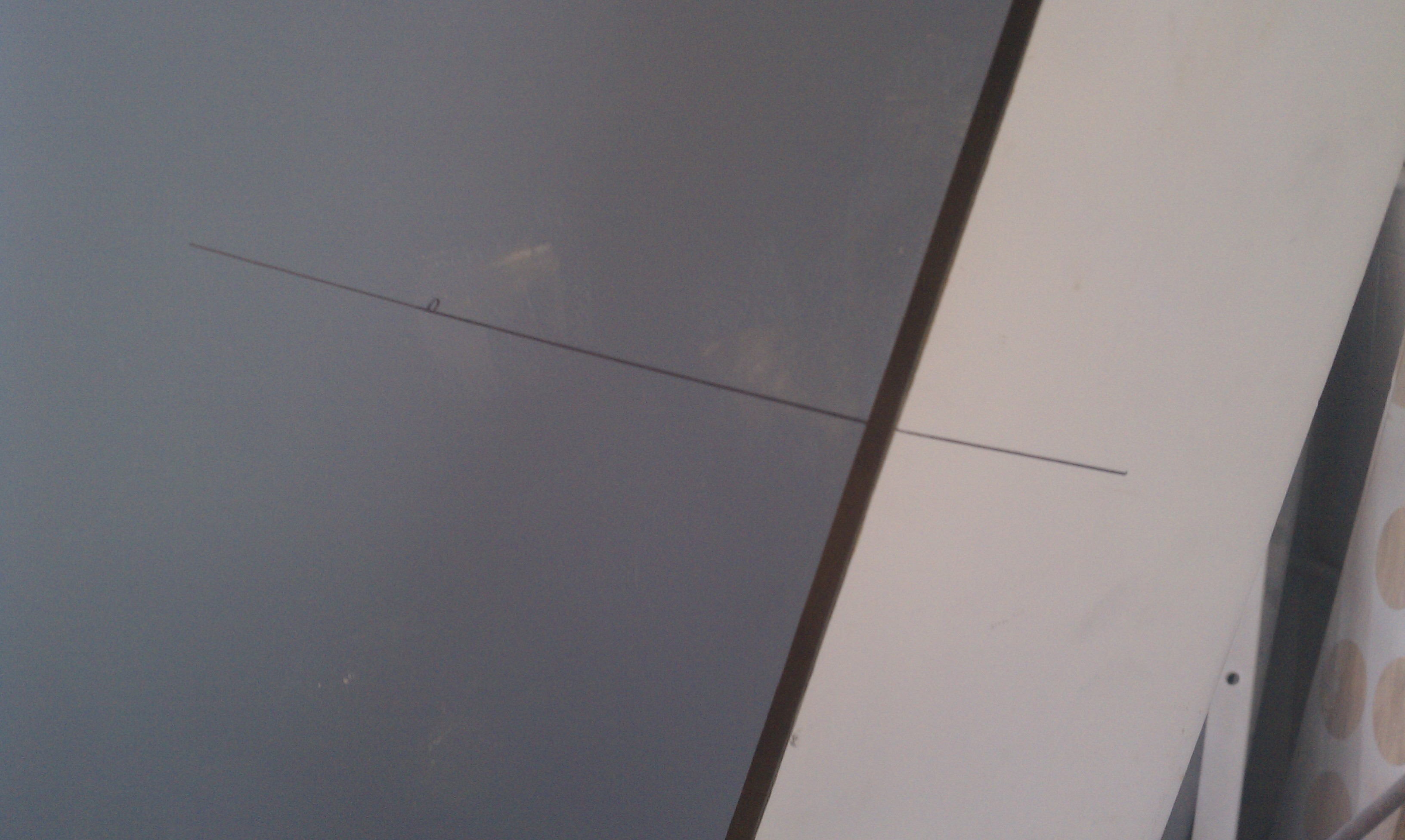
So a line is placed on the side of the winglet.

Closeup

Then a hole saw drill is chucked into the drill. Malcolm will make sure the drill is aligned laterally. I will watch from the side tell Malcolm whether he’s high or low. Once the hole is drilled, the spring sleeve is sanded, the hole is coated with an epoxy/cabo mix and the sleeve is inserted.

Here’s Malcolm drilling into the winglet. While he’s drilling, I’m saying “up” and “down” so he can keep the drill on line.

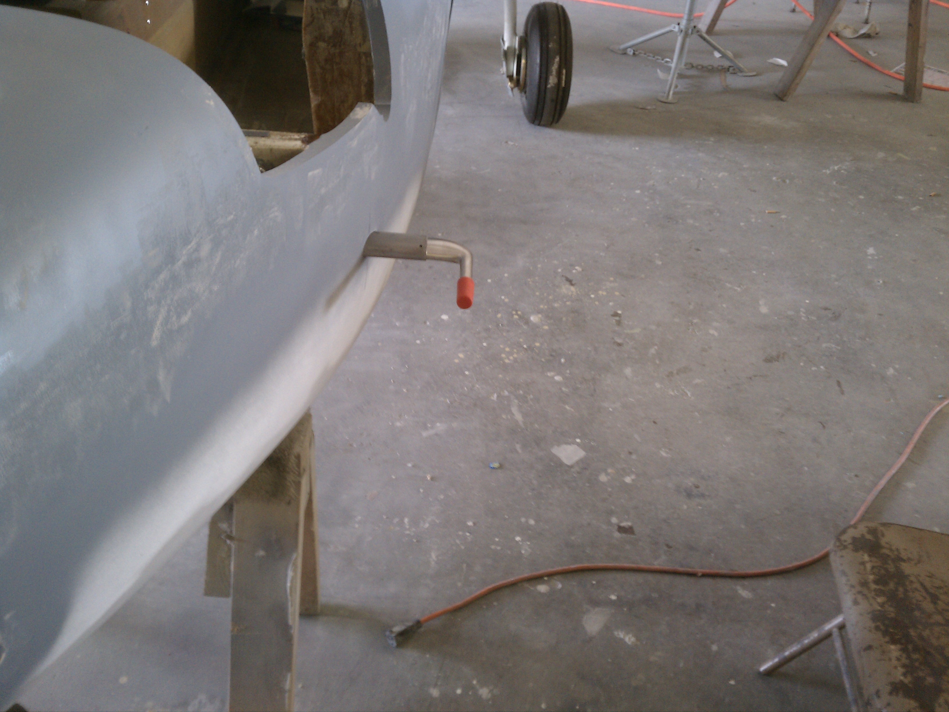
This is the rudder return spring epoxied in position.

Once this was done, the bottom of the rudder and aileron ends need to be covered with a layer of lightweight fiberglass.

This is the inside surface of the right aileron with a layer of fiberglass and peel-ply.
2011-05-02 1648 IMAG0299

13.4.3 Pitot Tube Installation

This entry is part 1 of 67 in the series 13 - Electrical / Instruments

The pitot tube is what measures the airflow so that we know how fast the airplane is moving through the air. This sucker was pricey too. Malcolm had some steel stock with the same cross-section as the pitot tube. So I cut a length of it and drilled four mounting holes in it.

The manual calls out the location of the pitot tube as 6.75 inches below the canard and 18 inches forward of the door.

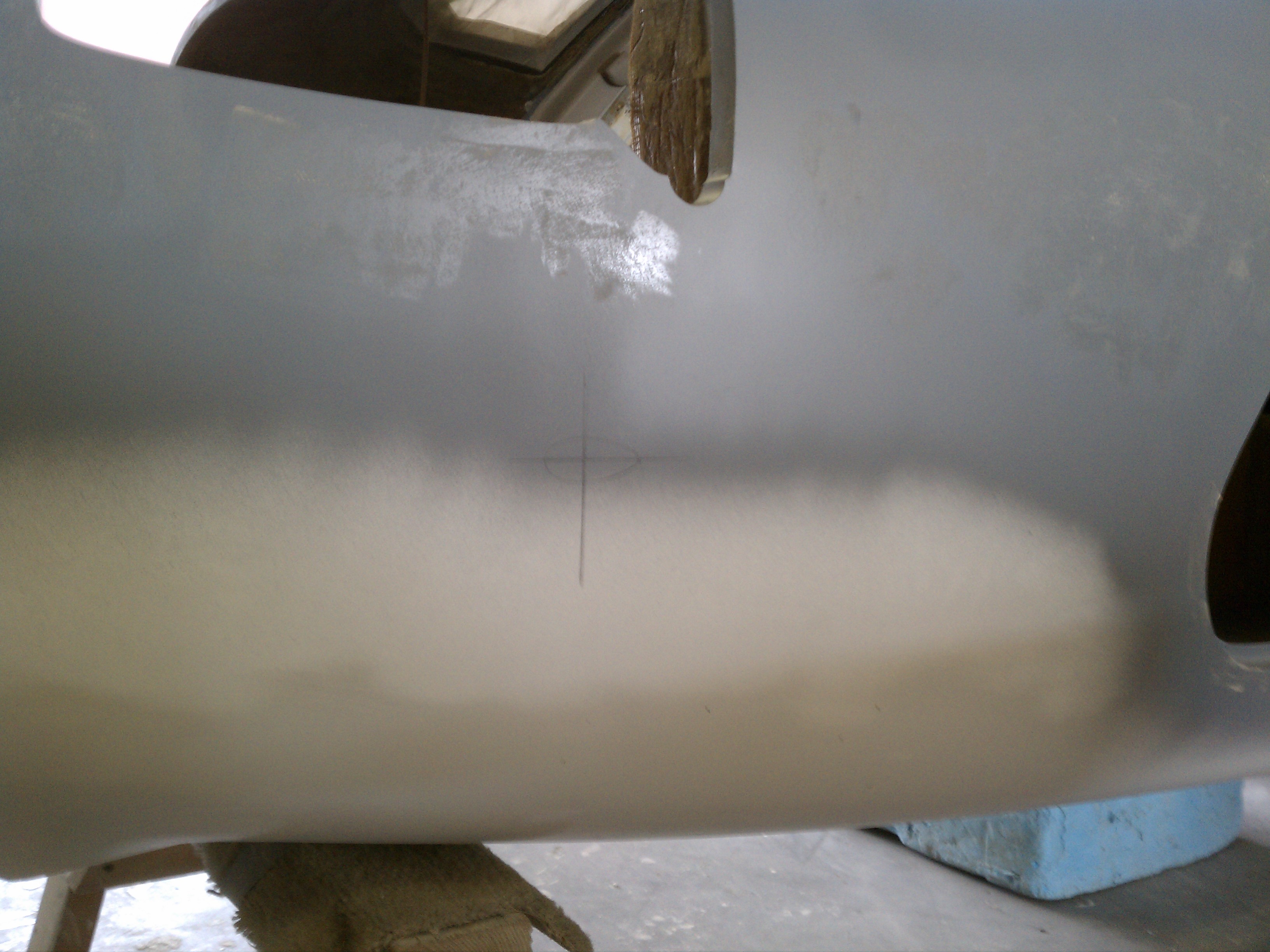
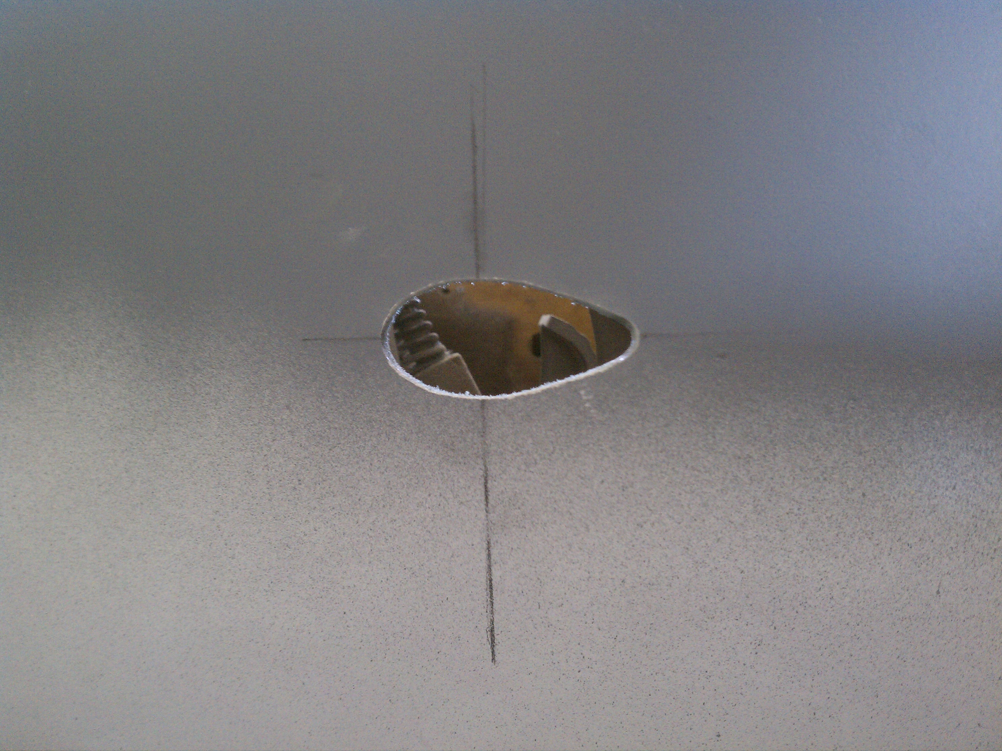
+ marks the spot.

Closer

And the hole is cut out.

The sleeve and pitot tube dry fitted.

Then the structural adhesive is mixed and the sleeve is permanently installed. The alignment is important to insure a correct airspeed indication.

Forward alignment is accomplished using a framing square clamped to the canard bulkhead and visually referencing the pitot tube to the framing square.

And we used a digital level to verify that it’s… level. The tripod is used to hold the position while the epoxy sets.

2.8.4 Rudder Horn Installation

This entry is part 3 of 8 in the series 02 - Wing / Winglets

Now that the rudders are mounted, the control of the rudders is the next task. The rudders are activated by a “horn” (basically a bellcrank) that is attached to the bottom of the rudder. But there’s a slight problem. The book says “Place your rudder horn on the bottom of the rudder.” But there’s no part number. Which would indicate that this is not a supplied part. But there’s also no template that is typically used to make one. A phone call to other builders indicate that this is supposed to be included in the kit. I’m sure that I could get the two horns shipped out to me. But where’s the fun in that???

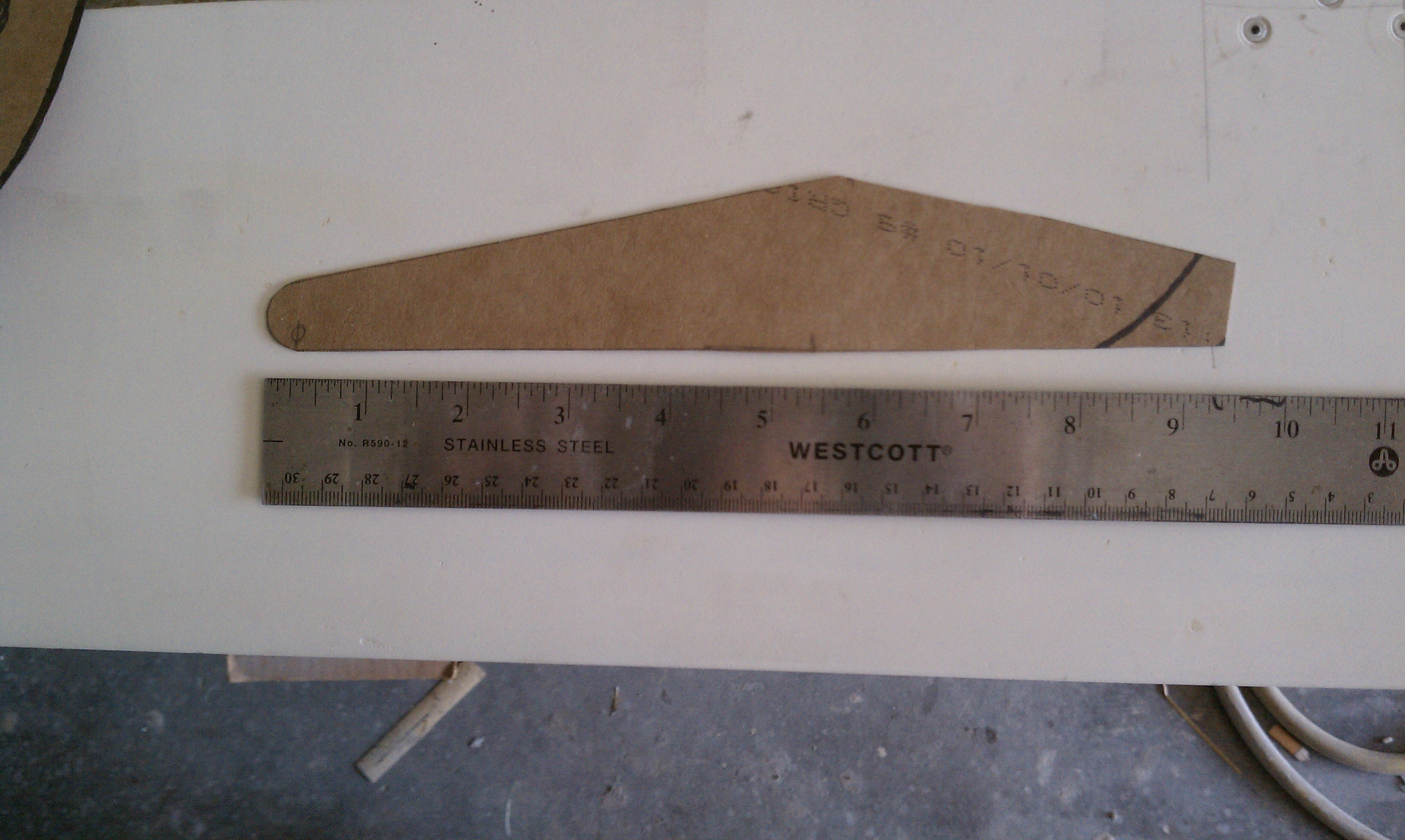
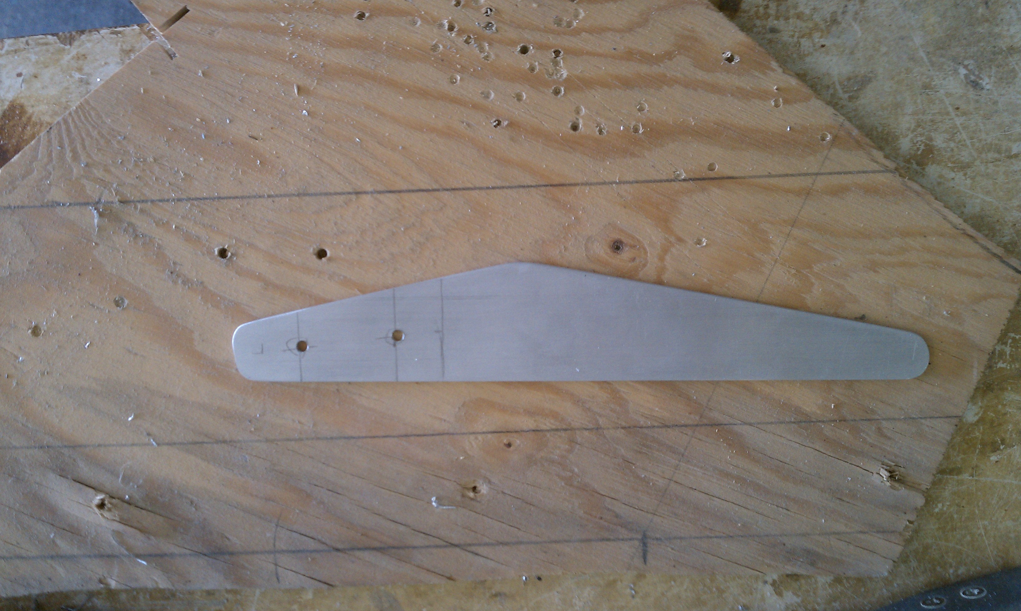
So the first thing I had to do is make a template.

This is the bottom of the left rudder. I’ve drawn a line to indicate how far the horn will extend.

Here’s the template held against the right rudder.

Since the rudders are a symmetrical, I only need one template. I’ll just need to flip it over to for the other rudder.

The rudder horn is mounted to the bottom of the rudder by means of a hardpoint embedded in the foam. But the hard point provided is a puny piece of 1/8″ aluminum about 1 inch x 2 inch square. I decided to upgrade to a 1/4″ hardpoint the covers the entire area under the rudder horn.

First I removed the foam where the rudder horn and hardpoint will go.

Then the web (fiberglass) is removed at the front of the rudder.

Here’s the hardpoint dryfitted.

And the rudder horn.

Then I filled the pocket with an epoxy/cabo mix, pushed the hardpoint in place and covered it with 3x BID.

After it cured, I trimmed away the excess and was left with this.

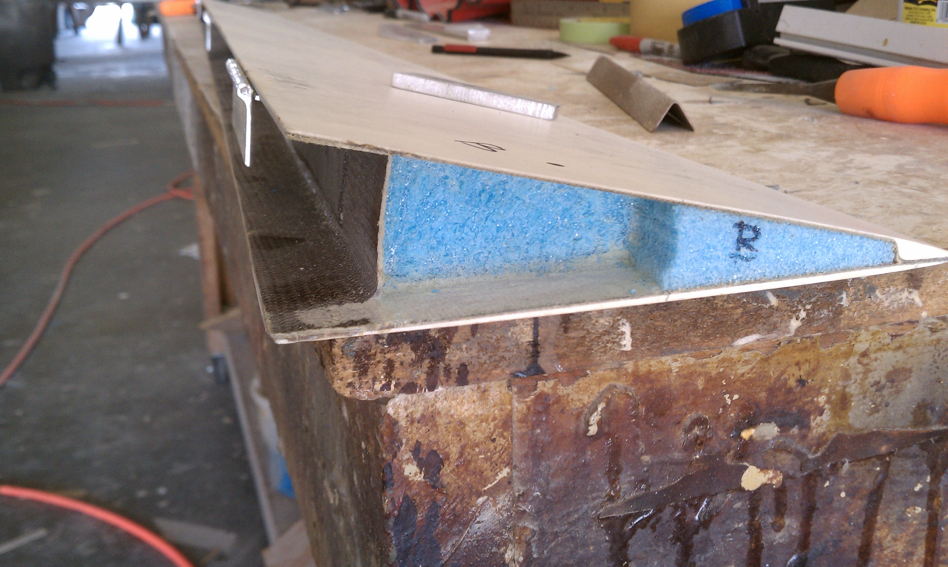
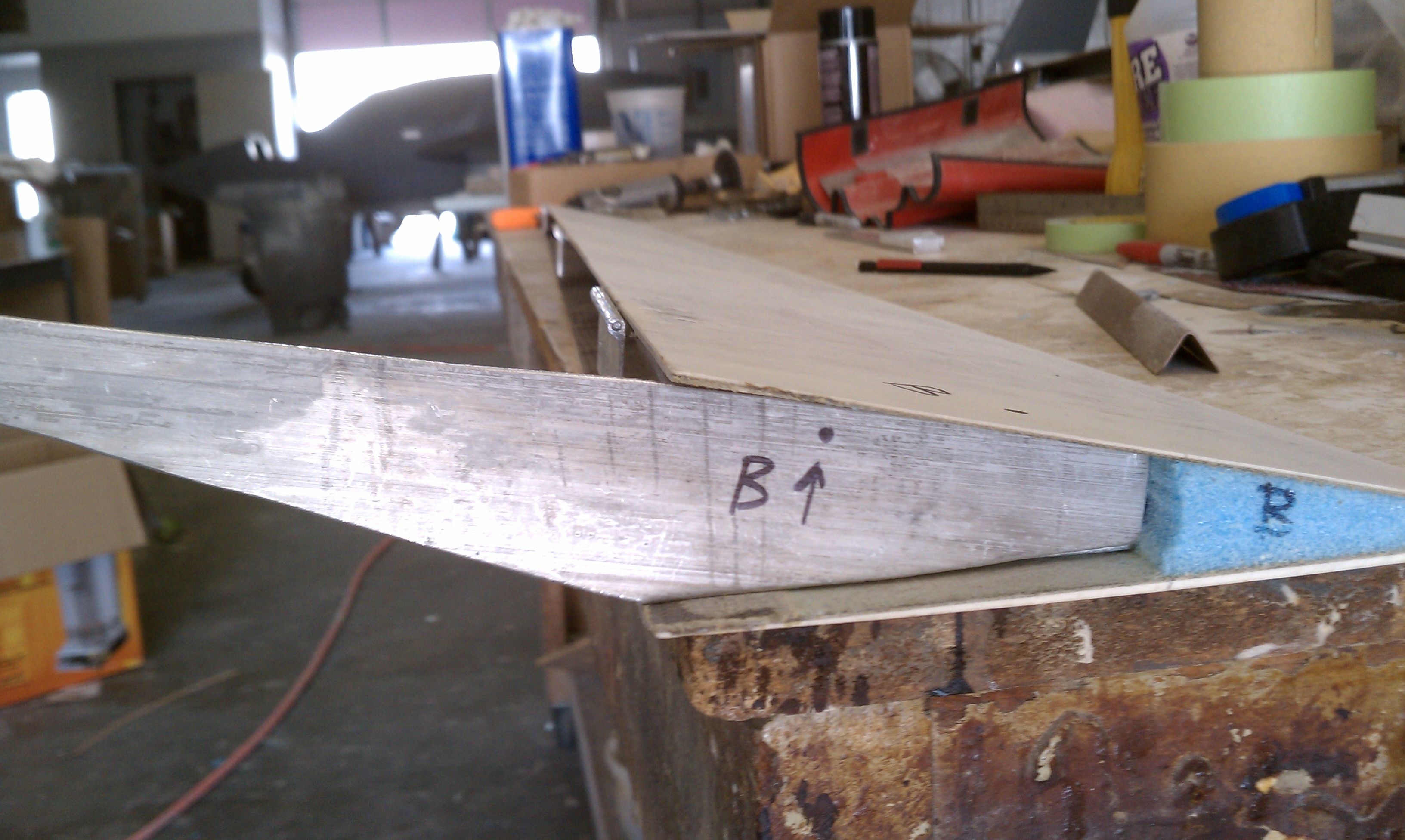
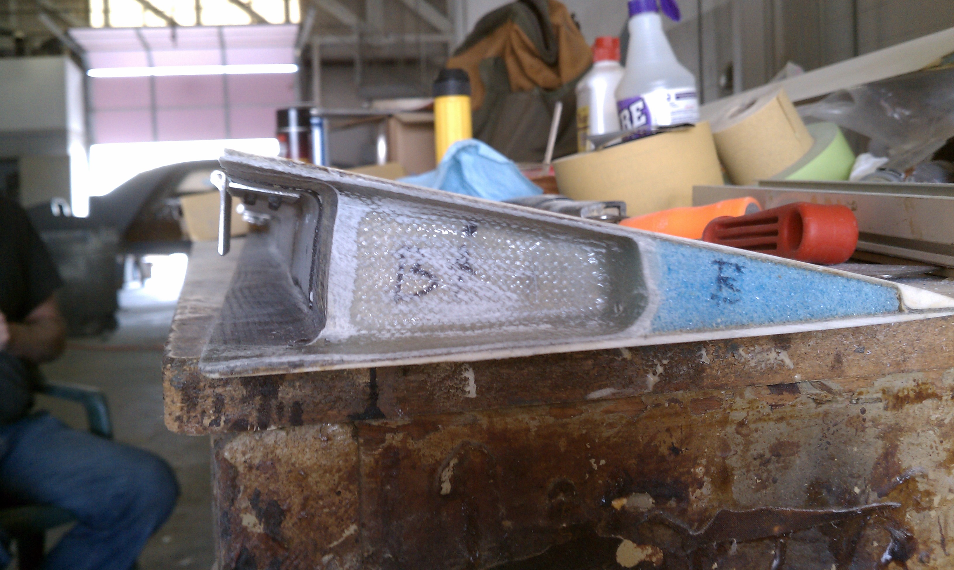
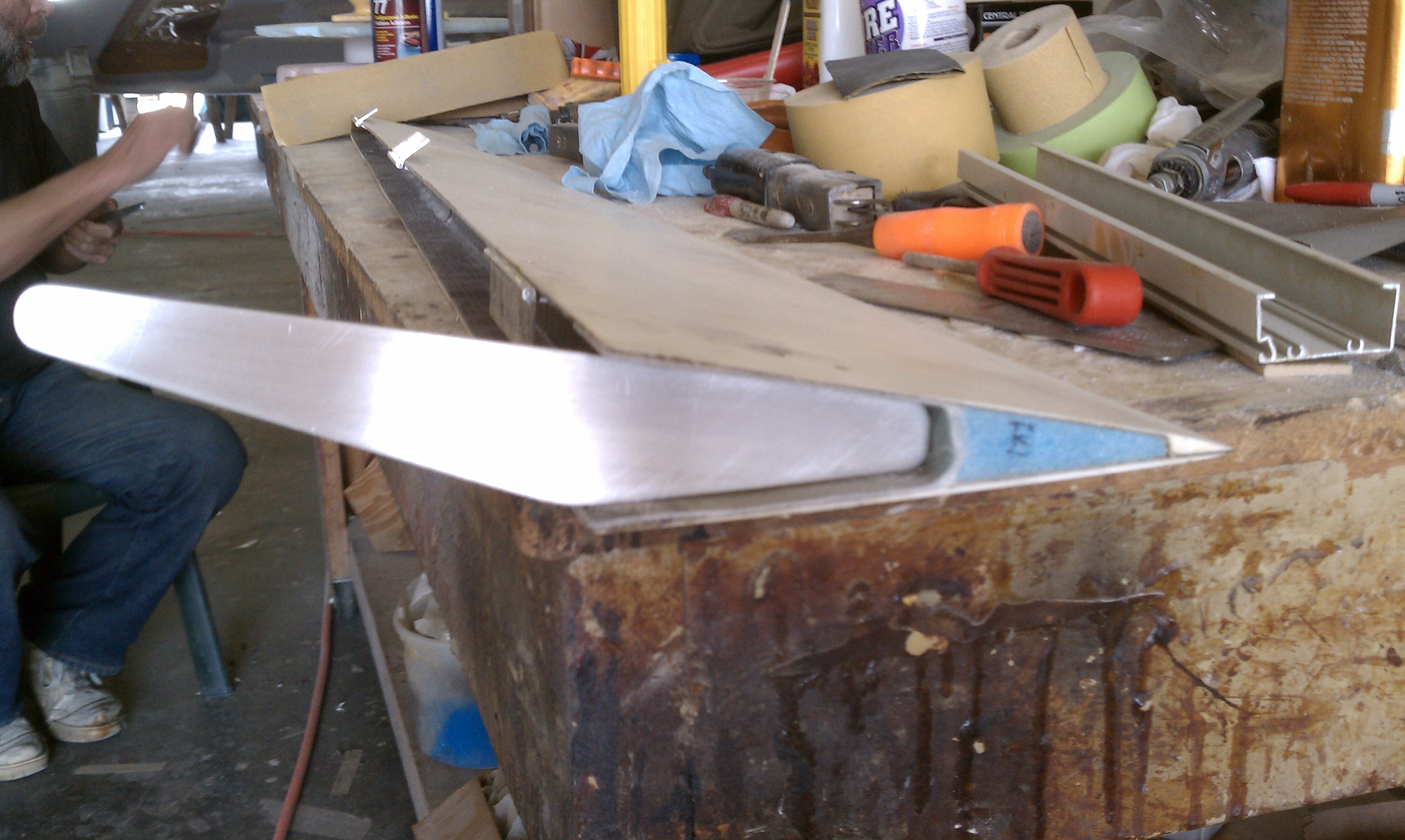
Then the rudder horns were sanded along the edges to remove any nicks from cutting and the fit was checked again.

Two holes were drilled for mounting

Then I put the horn in position, drilled into the hardpoints and tapped the holes.

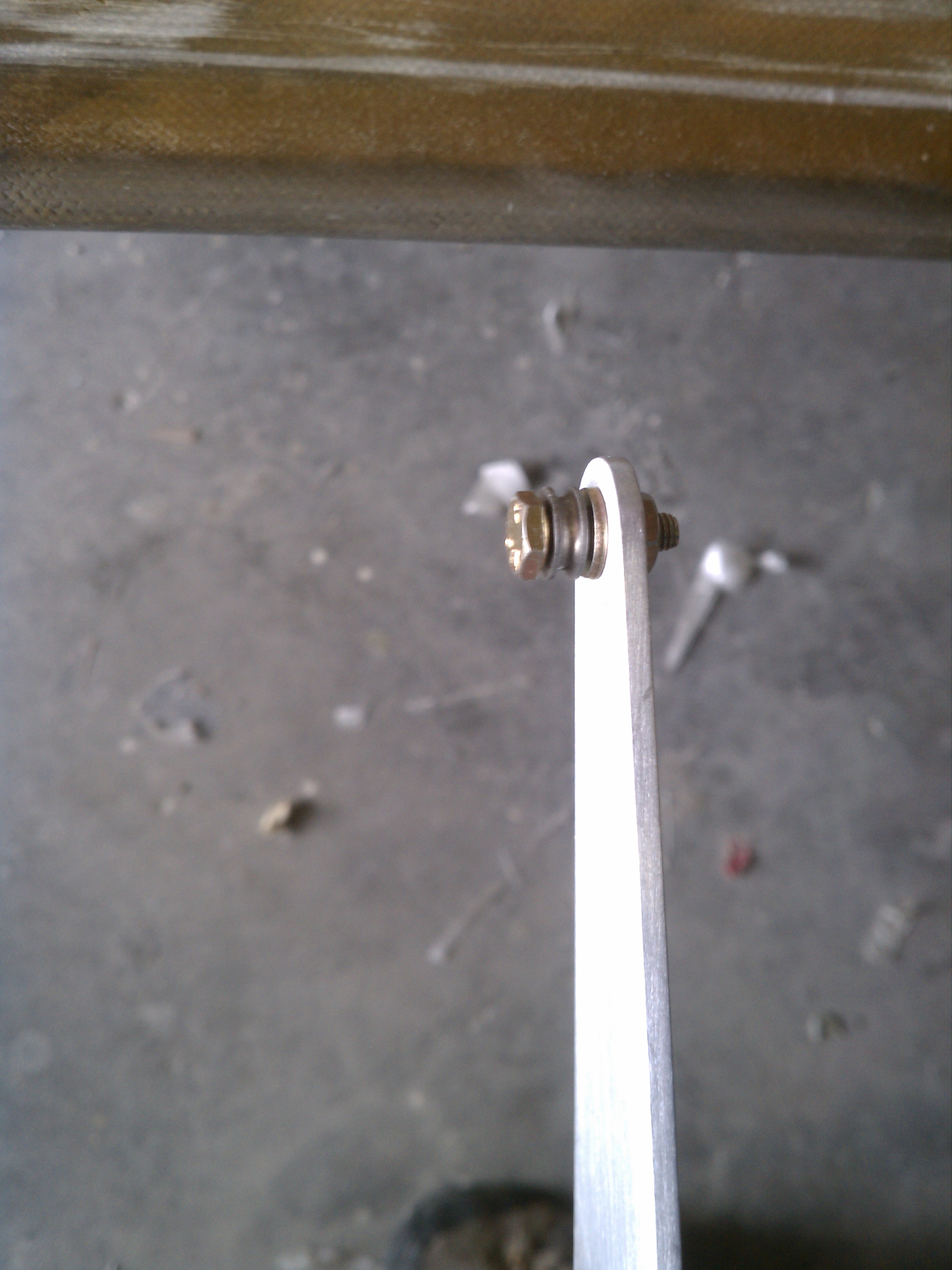
After that I drilled a hole in the end and mounted the rudder cable attach pulley.

Here’s the finished product.

And this is a factory hardpoint.

Not very impressive, huh?

11.1.5 NACA Duct modification

This entry is part 3 of 17 in the series 11 - Fairings

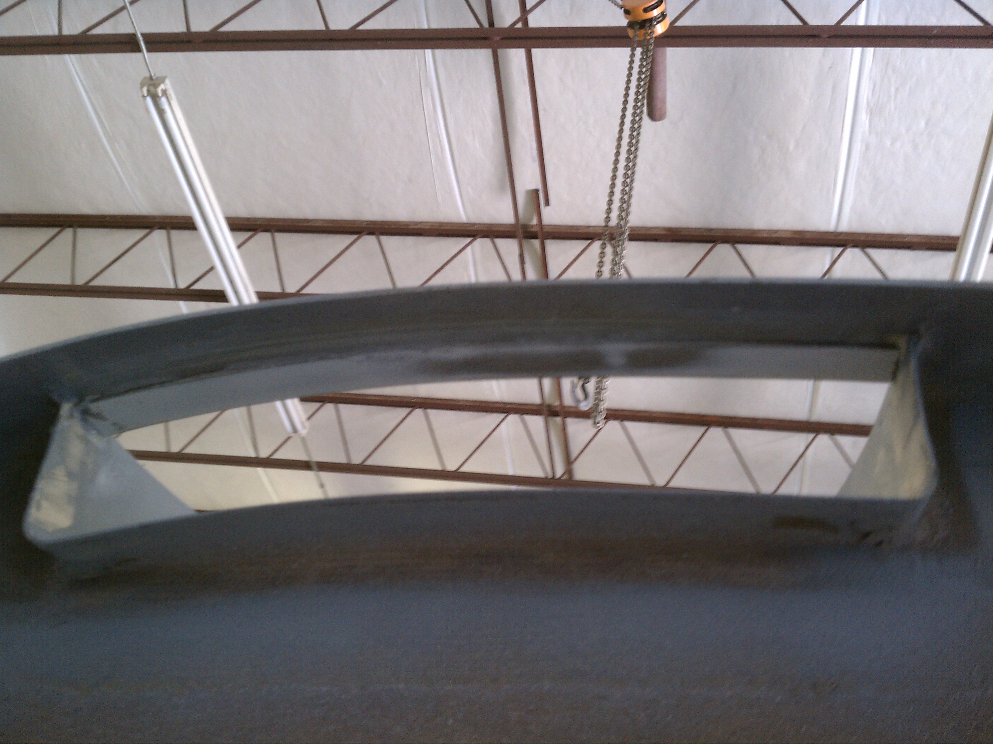
The NACA ducts provide cooling air to the engine. To obtain the maximum airflow (in my opinion) the path must be as smooth as possible. But I noticed a problem with this.

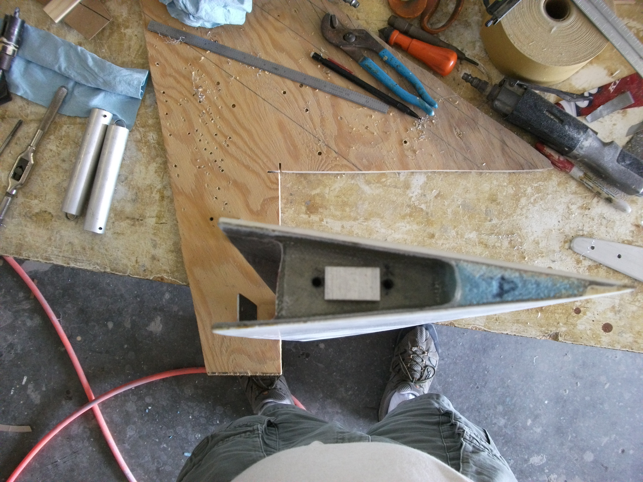
Here’s a picture looking up at the back of the pilot side NACA duct.

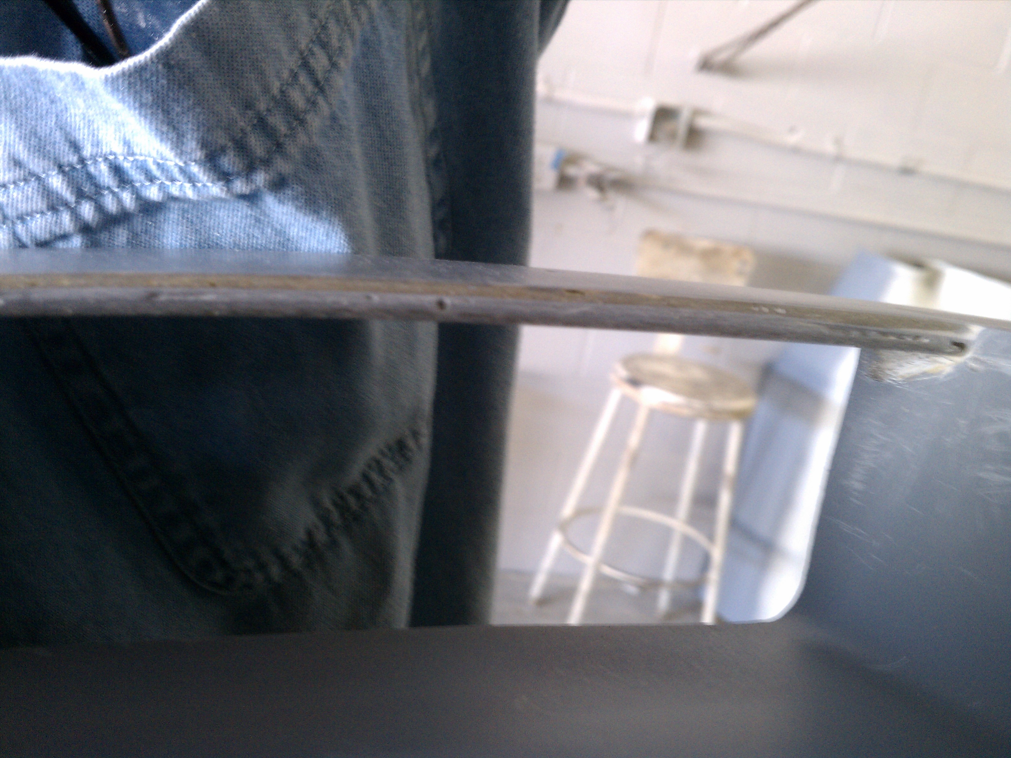
When the engine cowling is installed, there will be about an 1/8″ flange on the inside of the top of the duct.

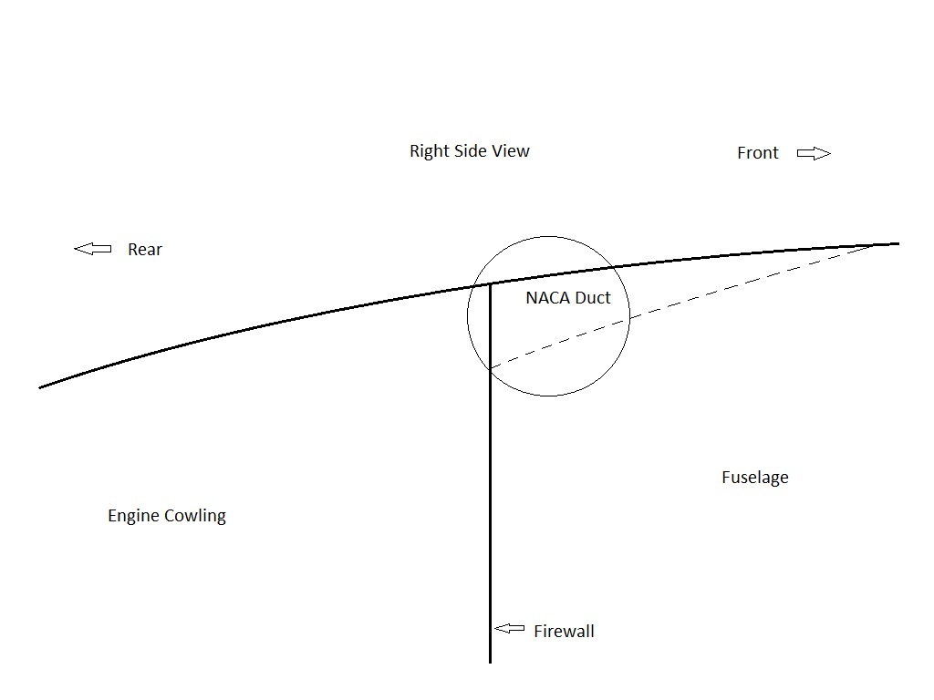
To illustrate, here’s a couple of drawings

Here’s the “big picture”. Looking at the right side of the airplane at the top. To the right would be the front of the plane, left is the rear and the vertical line is where the engine cowling meets the aft end of the fuselage. The circle shows the area of interest.

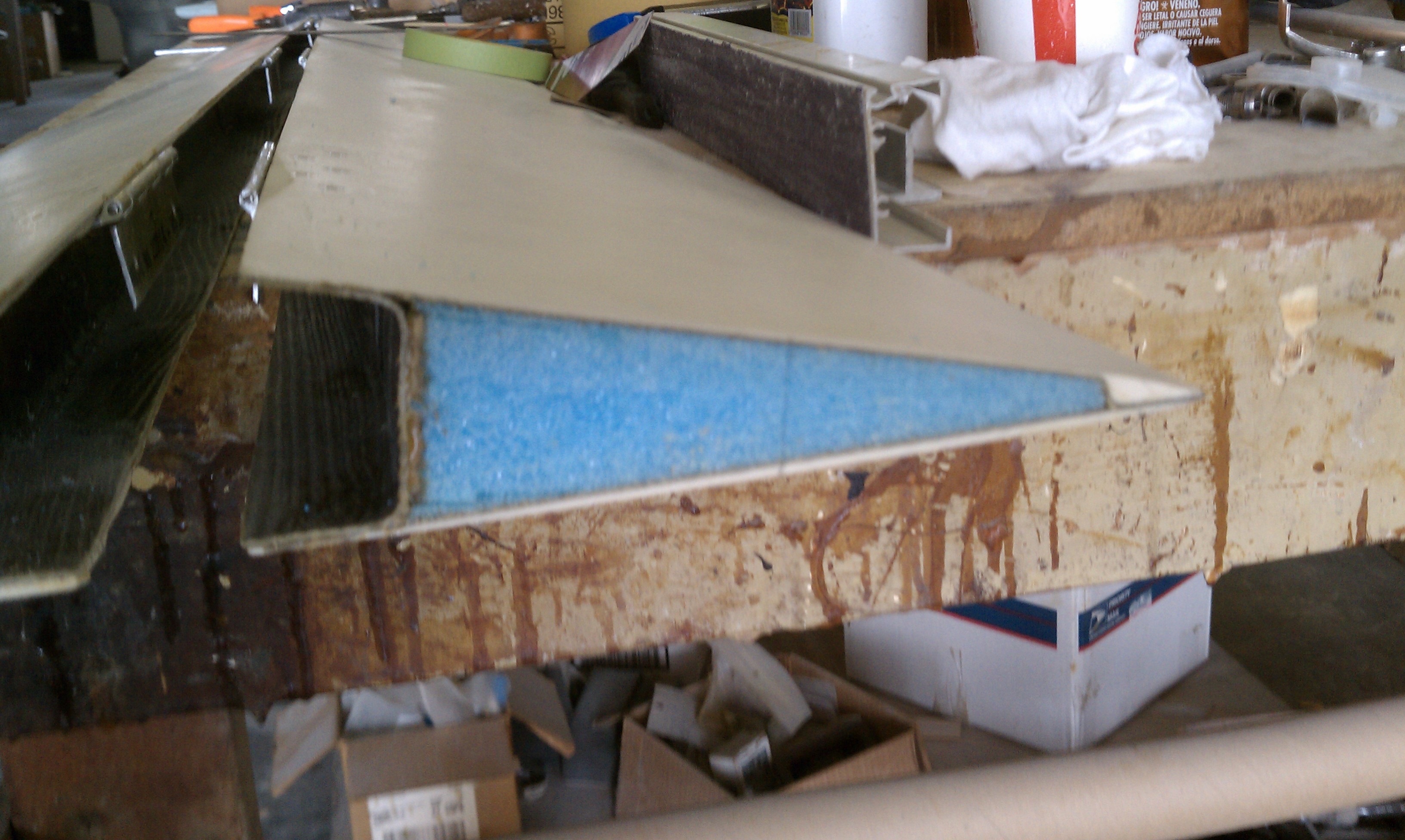
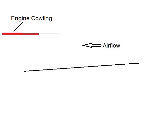
This is the enlarged view showing the bottom of the duct (sloped) and the top/rear of the duct.

Here’s the same view but with the cowling installed (Red).

Now instead of a smooth surface along the top, there’s a “step”. The other problem is that the factory ducts are missing an important feature which is a large radius along that top lip.

And now my solution. I’m going to glue a strip (Blue) in front of the engine cowling which will be the same thickness as the flange.

This will accomplish 1) smooth surface on the inside 2) a thicker radius and 3) a more rigid surface across the top of the duct.

Here’s the same view as before with the strip installed.

Then it’s time for Malcolm to work his magic. Creating a proper, uniform radius is an artistic thing. And I’ve come to learn that when it comes to something like that, it’s best left to Malcolm.

It was hard to get a picture of the leading edge of the lip. This is the best I could do.

14.2.1 Radius (Top)

This entry is part 7 of 38 in the series 14 - Final Assembly / FInishing

Before starting on the sanding of the primer, the radius at the strake/fuselage intersection has to be done (again). The bottom is already done, now it’s time for the top.

This is another one of those artistic things that Malcolm absolutely rocks at. 🙂

Malcolm whips up a batch of thick micro and puts in the corner. Then he uses his custom made radius tools to create a uniform radius. (I have to remember to bring my camera. These are with a camera phone)

The intersection between the winglet and the wing gets a radius too. Just slightly smaller.

14.2.1 Return of the Spotted Dog

This entry is part 6 of 38 in the series 14 - Final Assembly / FInishing

Return of the spotted dog

With the pin holes filled and the radius done, it’s time to sand. Most of the sanding should be uneventful. But some areas will be… enlightening. There were a couple spots on the wing where we just couldn’t figure out what was going on. High spot? Low spot? But with the whole area in gray, once we started sanding these areas, it became crystal clear. On the copilot wing, there were some low spots. But they aren’t low enough for micro and they were too low for primer.
Time for some backyard chemistry.

We decided to to mix micro balloon with the Akzo-Nobel gray primer. Since the micro balloon is inert, there shouldn’t be any reaction with the primer. I thought that we should do a small amount on a test area but Malcolm was absolutely certain there wouldn’t be a problem so we charged ahead. I mixed up the concoction and applied it with a roller (no way to spray it since it was real thick).

Here’s the result.

http://www.velocity-xl.com/pictures/2011/IMAG0349.jpg

I had to head home the following morning but Malcolm says that it cured fine, sands easy and filled the low spots.