More wiring…
The engine side terminal block and ground block is just about finished.


More wiring…
The engine side terminal block and ground block is just about finished.
I have all the wires routed from the bottom of the co-pilot A-Pillar up to the overhead switch panel (OSP). Because the switches that I’m using a very small, I can’t use the standard Faston connectors that most people use. So I had to solder on short pieces of wire that I will then crimp in-line Faston connectors to.
Here’s the overhead switch panel with the terminated pig-tails. The two in the middle near the middle that are terminated are for the magnetos, and the one towards the bottom is for the G3i ignition (that I haven’t gotten yet).

Here’s the A-Beam where the OSP will fit with the wires terminated (except for the mags. Red=Right and Blue=Left).

And here’s one of the mag leads.

Since I’ve installed a parking brake and I have a “Parking Brake Engaged” warning light, I need a way to activate the warning light when the parking brake is engaged.
I had been trying to figure out where to mount the switch. But then once the avionics shelf brackets were mounted, it became pretty obvious that was the place.
So first I had to make a mounting bracket.

Then drill a hole in the avionics shelf bracket and mount the bracket and micro switch.

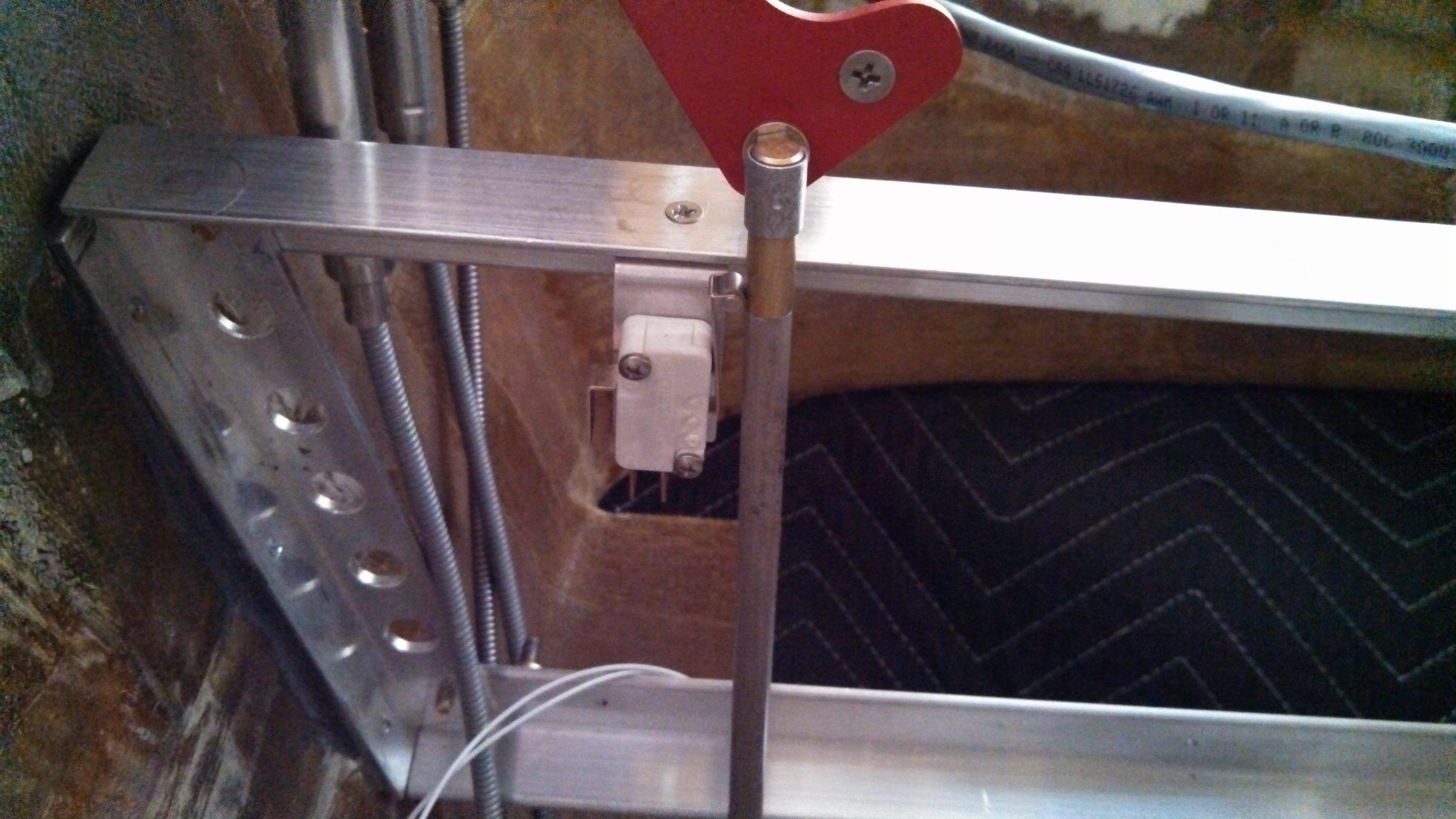
When the parking brake handle is in the “normal” position, the switch is open. Pull the handle a bit and the switch closes and the warning light comes on.
The main landing gear get two micro switches. One the sense the gear down and locked, the other to sense the gear is fully retracted.
The down and locked switch was easy. Just drill a couple holes in the tab. I did have to make a spacer to move the switch out so it would contact the over-center latch. When the gear is fully extended, the latch comes down, locks the main landing gear in place and depresses the micro switch.


The gear up switch was a bit more work. Once again, I had to make a bracket. But fortunately, it was just a straight piece of 1/16″ stock. Once the switch was mounted on the bracket, I retracted the gear, positioned the switch, clamped it in place, drilled and tapped the holes in the over-center link and then mounted the bracket.


The yellow stuff in the screw heads is Torque Seal. Also known as “anti-sabotage fluid”. Whenever I install something that is torqued, locked or is not coming off again, I put some torque seal on it. That way I know it’s done.


It may not seem like much, but the Master power switch and battery contactor are now wired up. I don’t have anything running off the electrical system yet so I hooked up the multimeter so verify.
One of the reasons for this is that while I was pulling wires and hooking up the overhead switch panel, I decided to test every wire, terminal and switch. Out of the dozen or so circuits, I found one that had a bad crimp on the terminal. It was relatively easy to troubleshoot and repair. Had I waited until everything was done, it would have been a major PITA.
So now, I test every single circuit when I install it.
Originally, I was going to use basic Molex connectors for the navigation and strobe light connections at the interface between the wing and strake. Then I found some weatherproof AMP connectors.

The wingtip light assembly has four wires (Ground, Navigation Light Power, Strobe Light Power and Sync) so I selected a 4-position connector.
Here is the fuselage side of the connection.

The red wire is the “sync” wire. This allows the strobe on the left to be synchronized with the strobe on the right.
Up until this point, I was labeling the wires with plain english (Oil Pressure, Starter, 24v, etc.). But after considering the number of labels and the cost of the heat shrink tubing, I decided that I should adopt the modified version of aircraft wire labeling standard. Hence the somewhat cryptic “L1-4B-20”.
Since the airframe is non-conductive fiberglass, I need a ground plane for the transponder antenna. Because the transponder operates on two frequencies, a circular ground plane isn’t optimal. I purchased a document from RST Engineering that provides the information needed to design antennas. But fellow builder John Tvedt had already built his some he sent me the template.
So I printed out the template and glued it to a piece of aluminum.

Then cut out the aluminum.

Drilled a hole and attached the antenna.

Now I just have to build the mount for the antenna assembly.
Instead of the traditional whiskey compass, I’m going to have an electronic magnetometer. And for redundancy, I’ll have two. I was originally planning on having one in the outboard pocket of the right strake and the other in the left. But builder Andy Millin put both of his in the same location. I was worried that there could be some interference issues if both were in the same location but it would appear that my worries were unfounded. 🙂
So I simply copied Andy’s design. Imitation is the sincerest form of flattery, right?
The support bracket is a 2″ piece of 2″x2″ angle stock. That will be screwed into a hardpoint which will be mounted to the outer part of the strake.
This the spot on the strake where the hardpoint will go. The area has been sanded and structural adhesive and been applied.
Hardpoint positioned and adhesive is cured. Now it covered with 2xBID.

The mounting platforms (one for each magnetometer) are made out of 1/8″ aluminum (which is much stronger that needed) with holes to reduce weight.

Then I cut some 1/4″ aluminum tubing to create the spacers between the two platforms. Some 1-1/2″ brass screws, washer and nuts later:


I’ve been spending a lot of time trying to figure out the best routing for the wires from the main gear position microswitches. I’ve looked at how other builders routed theirs and done a bunch tests. In the end, I put the wires in the nylon sleeves, then wrapped spiral-wrap around it and ran it across the over-center link and then down the pilot-side gear leg.
Here’s what it looks like.


Or you can watch it animated.

I bonded some wire attach pads to the underside of the over-center link and the gear leg. Then I used lacing cord to temporarily hold the harness while I cycled the gear. The tricky part is where the harness transitions from the over-center link to the gear leg.
Not quite as tricky but still important is where the harness transitions from the gear leg to the floor.

When I was building the mount for the magnetometer, I forgot that the outer strake bulkhead is not parallel to the centerline of the fuselage. The documentation for the magnetometer says that is can be calibrated for up to 127 degrees, but it was fairly simple to ream out the mounting holes to allow for that.
Here’s the modified bracket which compensates for the alignment.

To get the front-to-rear and side-to-side level, I put in the bracket with just the bottom plate. I used a level to determine how far out it was. Then it was just a matter of adding a washer or two and a little sanding to remove some material.

The finished mount with both magnetometers installed and ready for cabling.

