7.7.3 Main Gear Doors

This entry is part 10 of 39 in the series 07 - Landing Gear

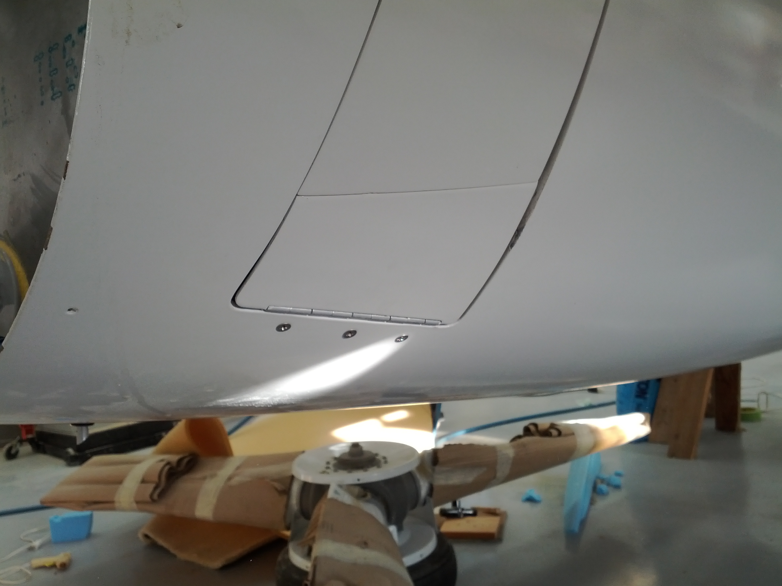
The build manual has you leave small openings at the bottom of the main landing gear doors. I built small “mini-doors” that will fill this opening. But now I have to figure out how to keep these little doors pushed out against the main gear doors.

Malcolm uses a thin strip of soft foam to apply the necessary outward pressure. But the geometry of my gear legs wont’ allow that. They keep ripping the foam off.

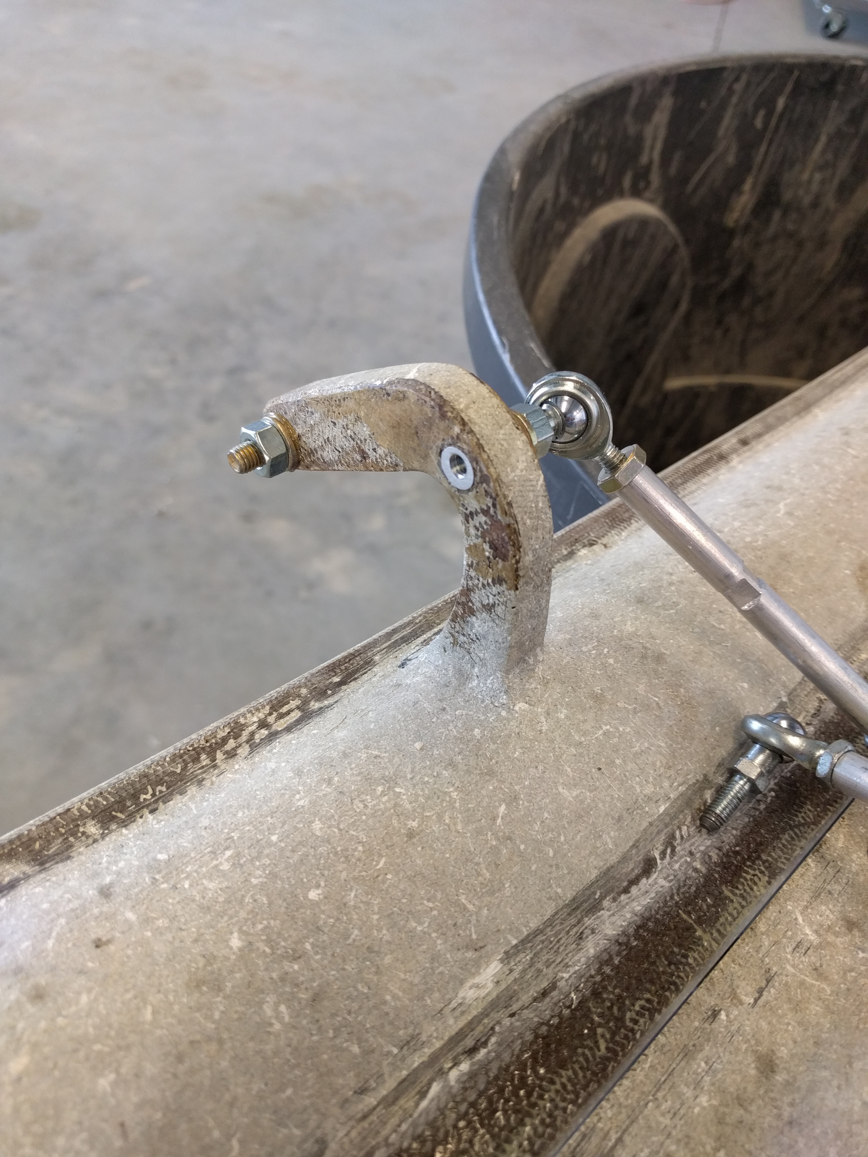
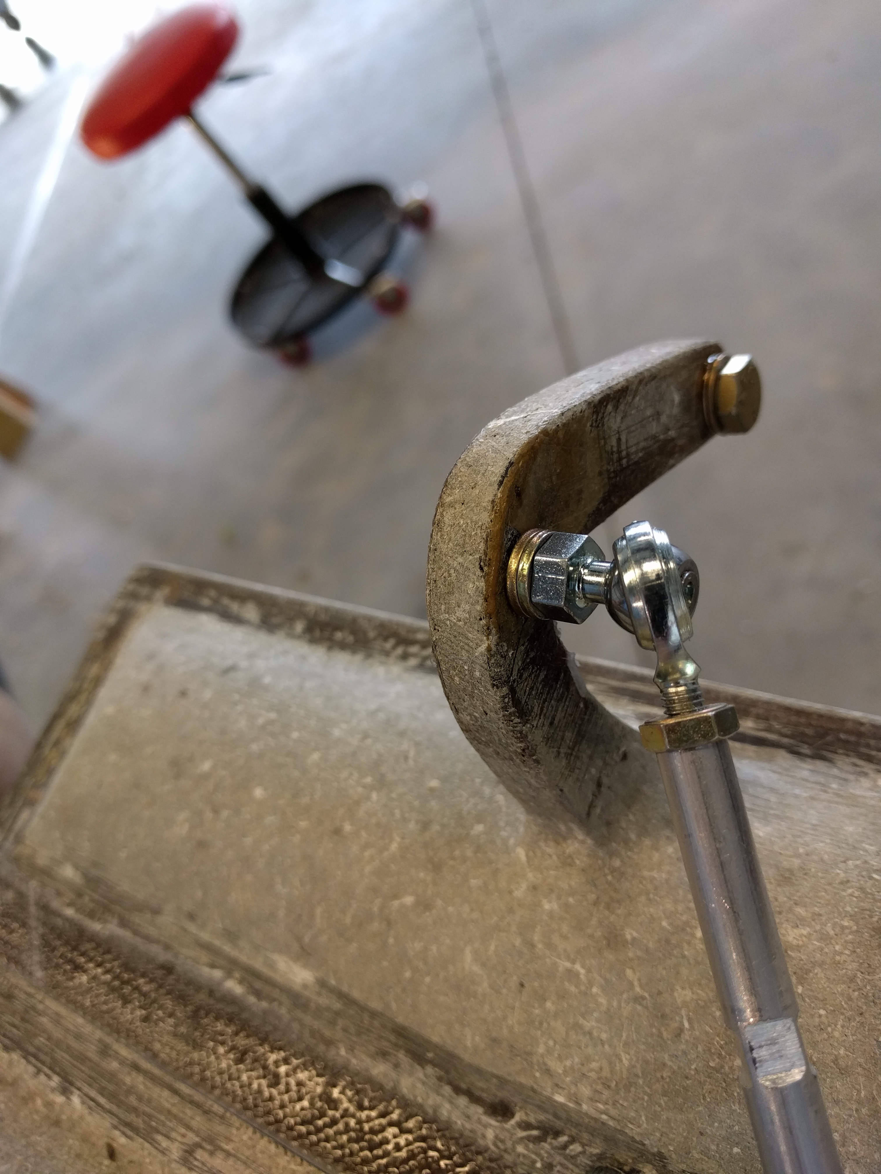
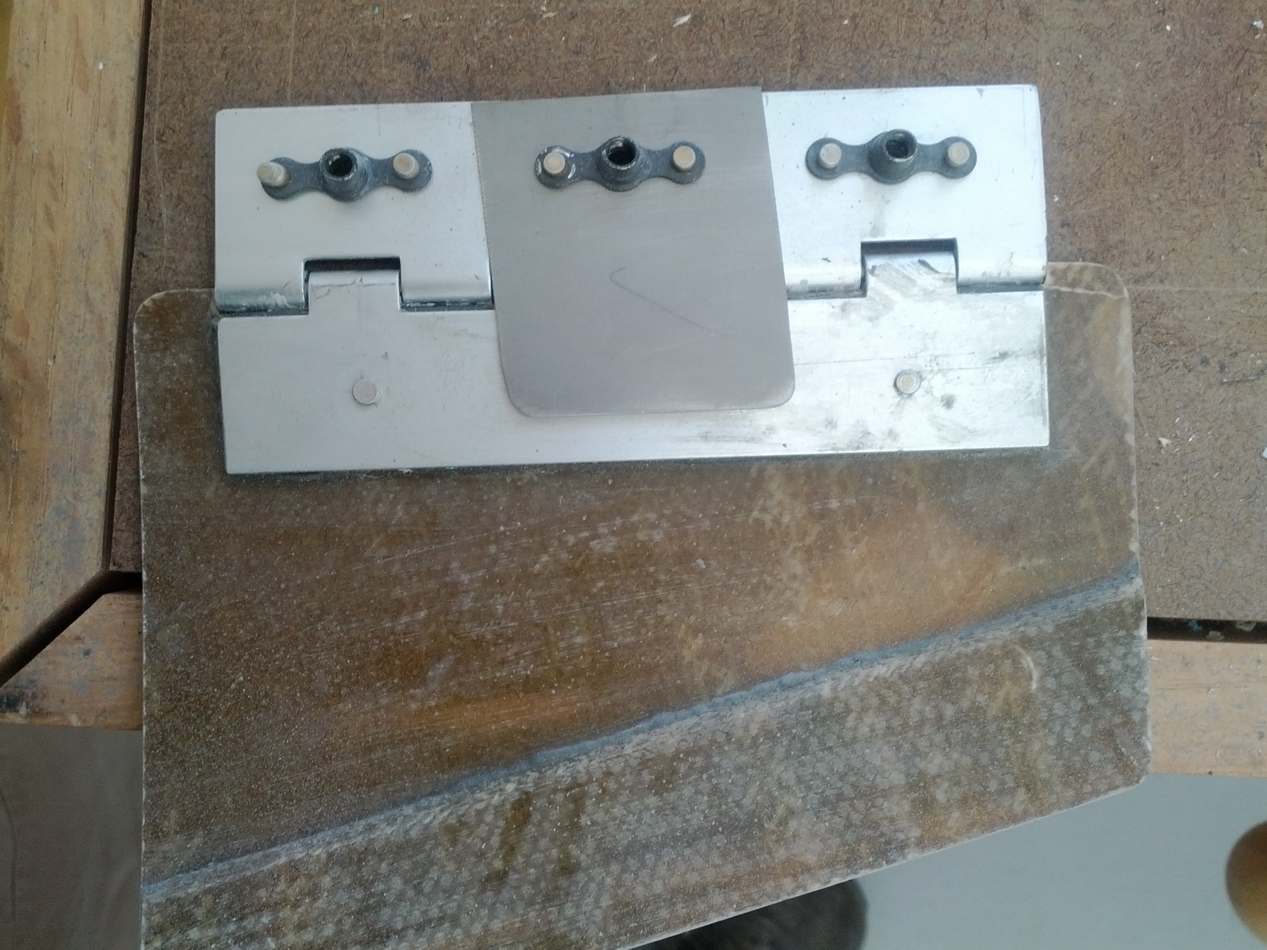
So I came up with a “Plan B” (I love a plan B). I cut a small piece of titanium and mounted it to the fixed side of the hinge. It’s damned near impossible to bend titanium so this tiny piece will hold the small door out with just the right amount of pressure.


Here’s the titanium tab sandwiched under the middle nut-plate.

Mounted with the gear up

And with the gear down (You can just see the tab between the gear leg and the door). It clears the gear leg by about 1/8″.


7.7.2 Parking Brake

This entry is part 11 of 39 in the series 07 - Landing Gear

I’ve already installed the parking brake valve. Now I have to decide how to actuate it. I thought about using a simple push/pull cable. But then I’ve got to allocate panel space to it (along with the knob protruding from the panel).

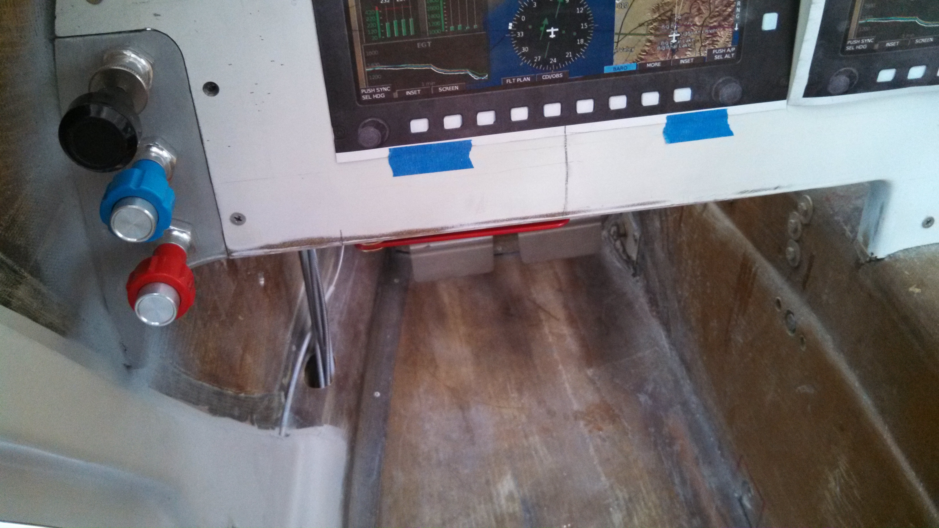
So I decided on a different approach. I made an “L” shaped bracket from 1/8″ aluminum stock and painted it bright red. This gets mounted to the lower edge of the instrument panel. Then I used some leftover 1/4″ aluminum rod which I drilled and tapped. Finally, the rod ends that were leftover from the factory nose gear door mechanism.

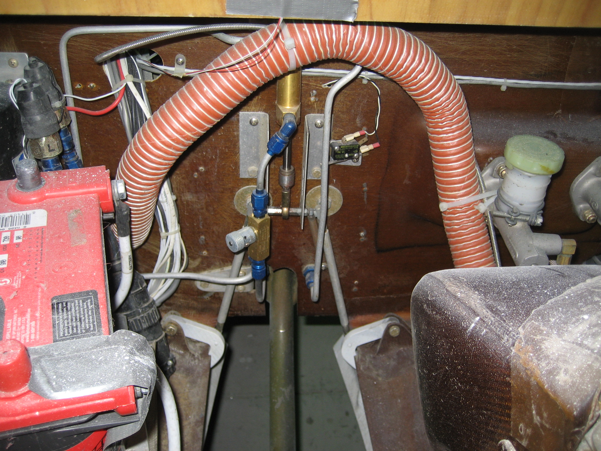
View from behind the panel. Parking brake valve is on the right, Actuator lever is on the left.

Looking the lever in the non-locked position from the pilot’s seat.

Looking the lever in the locked position from the pilot’s seat.

It will be pretty much impossible to not realize that the parking brake is set.


7.8.4 – Landing Gear Electrical

This entry is part 12 of 39 in the series 07 - Landing Gear

I needed an easy task, so I decided to install the nose gear down switch.

The switch gets attached to the overcenter stop. I put some blue tape to make it easier to see the location I marked for the holes.

Then I removed the stop, drilled and taped the holes for 4-40 screws.

Reinstalled the stop and mounted the switch.

The up switch is going to require some creativity.

7.8.4 Nose Gear Up Microswitch mount

This entry is part 15 of 39 in the series 07 - Landing Gear

There are a number of approaches to locating the position of the nose gear up microswitch. Most of the time some method of using the nose gear door is used to indicate the gear is up. I decided to locate mine there.

I took a small piece of aluminum angle stock, cut drilled and tapped one hole for the switch. The other hole I made a clearance hole and elongated it to allow for adjusting. Then I bonded it to the inside skin of the fuselage. Once the adhesive had cured, I covered it with 2xBID.

2013-09-17 IMG_20130917_083129_2702013-09-17 IMG_20130917_083143_824

Then I mounted the microswitch and adjusted it to activate when the nose gear door closed.

2013-09-17 IMG_20130917_130602_354a2013-09-17 IMG_20130917_130637_923


7.8.4 Main Gear Micro Switches

This entry is part 14 of 39 in the series 07 - Landing Gear

The main landing gear get two micro switches. One the sense the gear down and locked, the other to sense the gear is fully retracted.

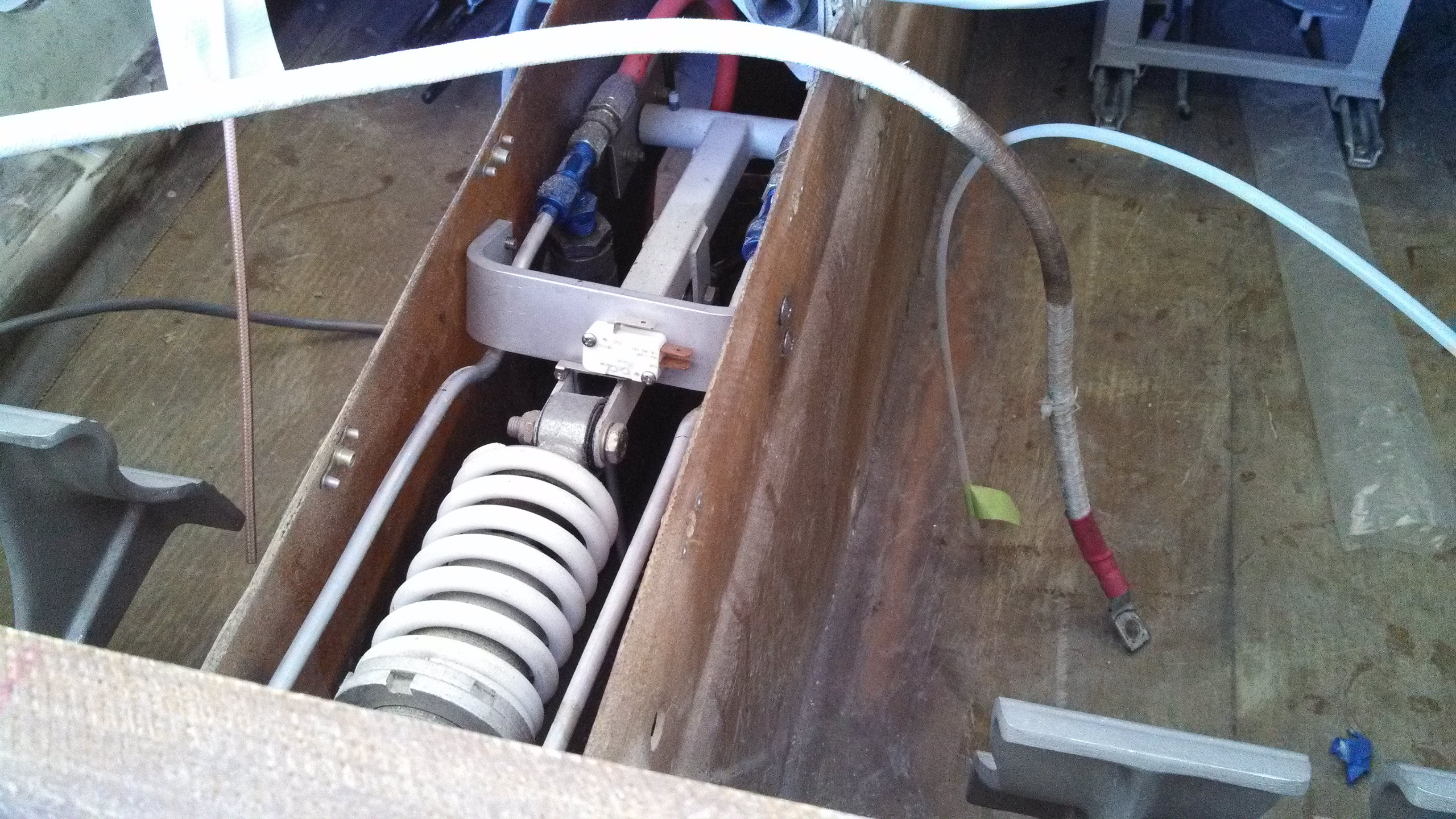
The down and locked switch was easy. Just drill a couple holes in the tab. I did have to make a spacer to move the switch out so it would contact the over-center latch.  When the gear is fully extended, the latch comes down, locks the main landing gear in place and depresses the micro switch.

2013-11-01 IMG_20131101_202623_830a2013-11-01 IMG_20131101_202555_315

The gear up switch was a bit more work. Once again, I had to make a bracket.  But fortunately, it was just a straight piece of 1/16″ stock. Once the switch was mounted on the bracket, I retracted the gear, positioned the switch, clamped it in place, drilled and tapped the holes in the over-center link and then mounted the bracket.

2013-11-02 IMG_20131102_165850_637 2013-11-02 IMG_20131102_165713_394

The yellow stuff in the screw heads is Torque Seal. Also known as “anti-sabotage fluid”. Whenever I install something that is torqued, locked or is not coming off again, I put some torque seal on it. That way I know it’s done.


7.8.4 Main gear microswitch wire routing

This entry is part 13 of 39 in the series 07 - Landing Gear

I’ve been spending a lot of time trying to figure out the best routing for the wires from the main gear position microswitches. I’ve looked at how other builders routed theirs and done a bunch tests. In the end, I put the wires in the nylon sleeves, then wrapped spiral-wrap around it and ran it across the over-center link and then down the pilot-side gear leg.

Here’s what it looks like.

2013-11-08 IMG_20131108_175300_3472013-11-08 IMG_20131108_175318_8852013-11-08 IMG_20131108_175354_4212013-11-08 IMG_20131108_175412_359

Or you can watch it animated.

output_fy4SjL

I bonded some wire attach pads to the underside of the over-center link and the gear leg. Then I used lacing cord to temporarily hold the harness while I cycled the gear. The tricky part is where the harness transitions from the over-center link to the gear leg.

Not quite as tricky but still important is where the harness transitions from the gear leg to the floor.

2013-11-08 IMG_20131108_175421_131

Nose gear spring replacement

This entry is part 37 of 39 in the series 07 - Landing Gear

Bouncing along on a amusement park ride.

That’s what one of my landings felt like. But it wasn’t my fault!  Runway 05/23 at Sebastian is not a very smooth runway.  Lots of dips.  On the above referenced landing, I hit one of these dips and got catapulted into the ceiling.  Now even with my seat and rail system modified, I don’t have much headroom… so at least I didn’t develop much momentum.

I think it was the day after that landing I was rolling up to the builders service center and Scott was watching me taxi up.  He had a very concerned look on his face.  Which was causing me to get a very concerned look on mine.

I shut down and got out and said “What?!?!”. He said “Something’s not right with your nose gear strut.”  Then he walked over and with one hand pushed down on the nose. When he did, the nose when down and the nose wheel sprung forward.  Then he said “This spring is too weak.  I shouldn’t be able to compress the spring at all.”

Normally, it would take a putting the weight of your whole body on the nose to begin to compress the spring.

At some point in the past, Velocity had some weak-ass springs. Scott asked what color my nose gear spring was. I told I wasn’t sure but I would check tonight. He said it felt like one of the white ones.  So I put the airplane away for the night and once back at the hotel, I looked through my pictures.

From January 25, 2008…

2008-01-25 1026 IMG_5873

Uh-oh.

The next morning, I taxied over to the Builders Service Center.  Scott was waiting.  “Well?” he asked.  I just shook my head.  He was visibly unhappy. “I thought that we found everybody that had a white spring and replaced them.”

He said the biggest danger is that when the spring compresses enough, the top of the gear is not supported against side loads.

Here’s a diagram that shows the nose gear assembly from the left side.

Nose Gear

This is showing the “Down and Locked” position. At the bottom of the nose gear is the wheel (out of the diagram, bottom left). At the top is the spring (in red). The blue “captivator” is a U-shaped steel bracket which prevents the top of the assembly from moving left to right. When weight is put on the nose of the plane, the spring compresses, the wheel moves up (and forward) and the top of the assembly moves back. If it’s just a little, it’s not a problem. If the top moves back enough, the top is no longer in the captivator.

The big problem with my weak-ass spring is that with just my weight in the pilot seat, the spring was already compressed some. Any bump (or another person in the front seat) and the spring is compressed enough so the top of the gear assembly is now out of the captivator. Which means a nose gear collapse is just a matter of time.

Scott then asked about my takeoffs. I told him the plane stays firmly on the ground until I pull up. He nodded and said “Yep. That’s what I figured.”  With the pitch trim set for takeoff but the spring compressed, the canard was not at the normal angle of attack. So it’s not creating any lift.  But once I pulled back on the stick just enough, the spring would uncompress, and the canard would then generate lift and the plane leaps off the ground.

So now what?

Scott said it’s not too bad of a job to pull the shock out.  So I started by removing the canard. Then it’s just the two bolts at either end of the shock.  It took me about an hour.

Then we rode over to the machine shop where Scott had already pulled a new (red) spring. With a special fixture for the press, the old spring was removed and the new one installed in about 3 minutes. Without a press, that would have taken me a whole day to figure out how to do that.

Another hour to put everything back together and Charlie Mike was ready to go. Total time, about 2.5 hours. That right there made the numerous trips back and forth between Panama City and Sebastian worth it.  If I hadn’t been there, Scott wouldn’t have noticed it. And I wouldn’t have since I didn’t have enough Velocity time to know that is was too soft.

The next takeoff was so much nicer. The plane literally flew off the runway. And the landing was so much better as well.

7.2 – Nose Gear Door Actuator Replacement

This entry is part 38 of 39 in the series 07 - Landing Gear

Early on in the build, I decided that I didn’t like the idea of closing the nose gear doors using hydraulics. There’s a lot that can go wrong there and it’s a more complicated approach.

IMG_5822

Hydraulic lines, cylinders, switches, etc. Yuch!

Fellow Builder Terry Miles had a nice solution that I liked.

IMG_9583

Another guy who had also come up with a mechanism was Ken Mishler. And he sold these.  So why reinvent the wheel?

Wolf DSC_0190

Unfortunately, Ken wasn’t making any at the time and didn’t know if he would. So I found a local machinist, drew up some plans and ended up with my version of the Terry Miles actuator.

2010-07-22 0610 IMG_0668

This worked very well. Went overcenter with the gear down and closed the doors when up. But it had three problems.

  1. It had a very narrow range of adjustment.  Basically, you could adjust the linkage. That’s it.
  2. Adjusted with the doors closed, the tire would rub on the door when spinning. This created a burning rubber smell in the cabin.
  3. With the gear up and doors closed, any increase in air pressure in the nose would cause the doors to open slightly. Two things caused this: a) air leaking from the nose oil cooler. and b) Air leaking into the nose through the gear doors.  Either of these would cause the “Gear Unsafe” warning light to come on.

There was a simple fix to these problems; Longer arms.  But my machinist was retired which meant that I didn’t have anyone to make me a new set.  I could have kludged on some extensions, but that’s not a good way to do things.

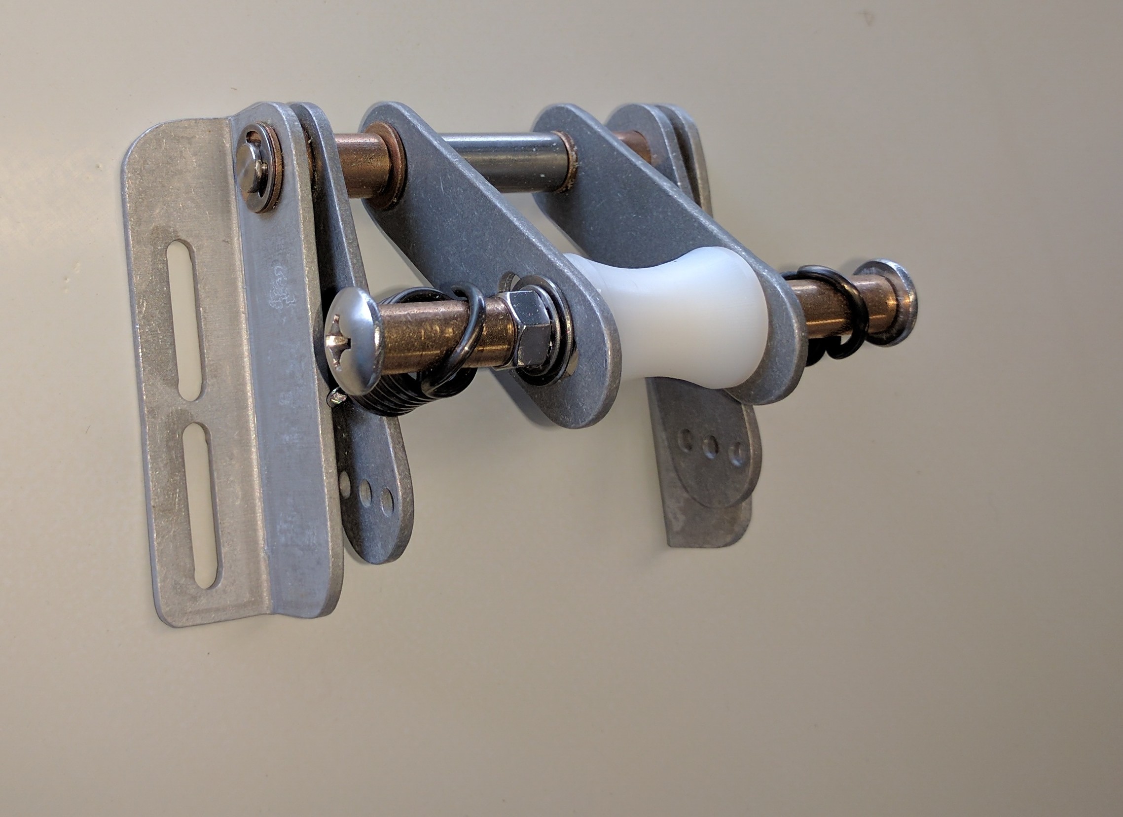
Then I found out that Ken was making his actuators again.  A bunch of people have installed these so I ordered one.

2016-11-30 IMG_20161130_133353

Nicely built, the spring provides some give in the system so the doors stay closed even if the nose gear bounces a bit.

It also came with the rod ends to connect to the gear doors.

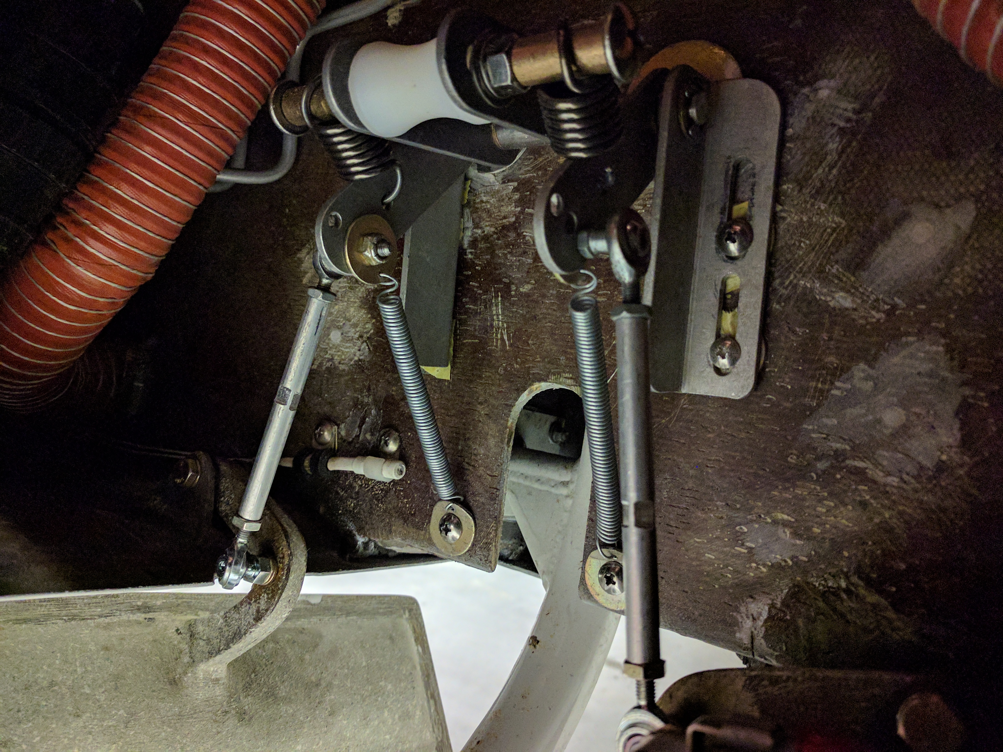
I used 1/4″ aluminum rod for the connecting rod between the upper and lower rod ends. First I had to determine the correct length of the base connecting rod.  So I installed the actuator in what I thought would be the best location. Then I measured the distance from the holes on the actuator to the holes on the gear door arms. Then I subtracted the length of the rod ends (to halfway the threaded part).  This gave me the length of the connecting rod.

I cut a pair that length (I think it was 3-1/2″) and started to drill the holes which would receive the rod ends. This brought me to my first, seemingly insurmountable problem. How do you drill a 5/32″ hole in the end of (what is effectively) an 8/32″ rod and be exactly in the center without wandering?  The obvious answer is a lathe. But I don’t have one nor do I have access to one.

So this is how I got around that minor barrier:

I chucked each piece of the 1/4″ rod into my drill.  Then I smoothed and flattened each end.

Next I got some 1/2″ (ID) tubing that I had laying around and cut off a piece about 3″ long.

Then I wrapped some tape around the 1/4″ rod near the end so that it just fit inside the 1/2″ tubing.

I then took a 7/16″ drill bit and clamped it in the bench vice and wrapped some masking tape around it until it just fit into the tubing.

Now I’m ready to go.  I chuck the 1/4″ rod into the drill, slide the 1/2″ tubing around it (the tubing extends past the end of the rod by about an inch), slide the end of the tubing over the 7/16″ drill bit and slowly start drilling. You just need to go a little because all you’re doing now is creating a pilot for drilling with the #21 bit.  By doing it this way, the pilot is almost exactly in the center.

Now slide the 1/2″ tubing off the rod, put a #21 bit in the vise, get the bit in the pilot that you just created and start drilling. Since you’re turning the stock instead of the bit, the hole will be perfectly centered in the rod.

Do that four more times and both end of the two connected rods are now drilled and ready for tapping the end with a 10-32 tap.

Here’s what it looked like after assembly:

2017-01-18 IMG_20170118_123722

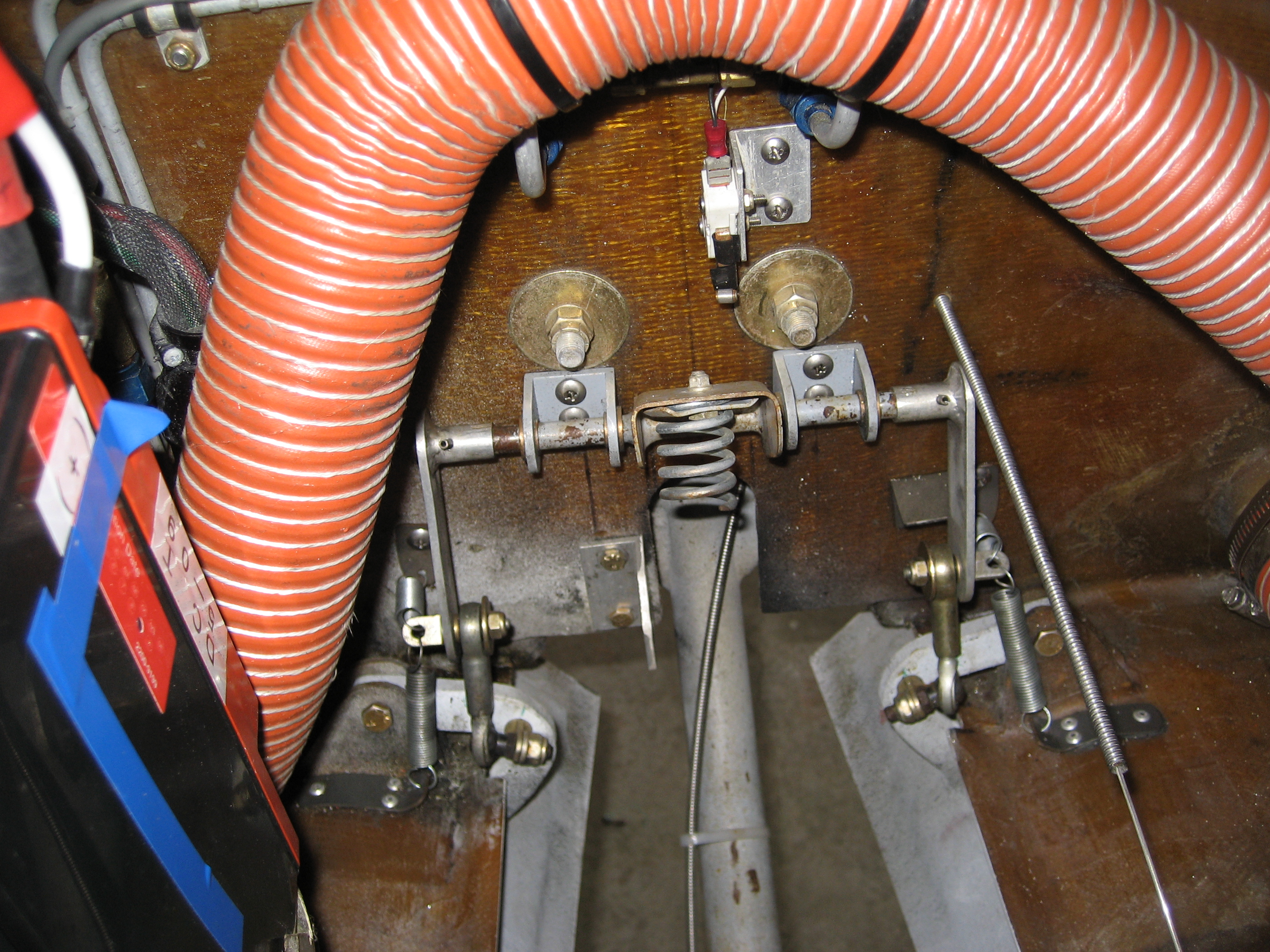
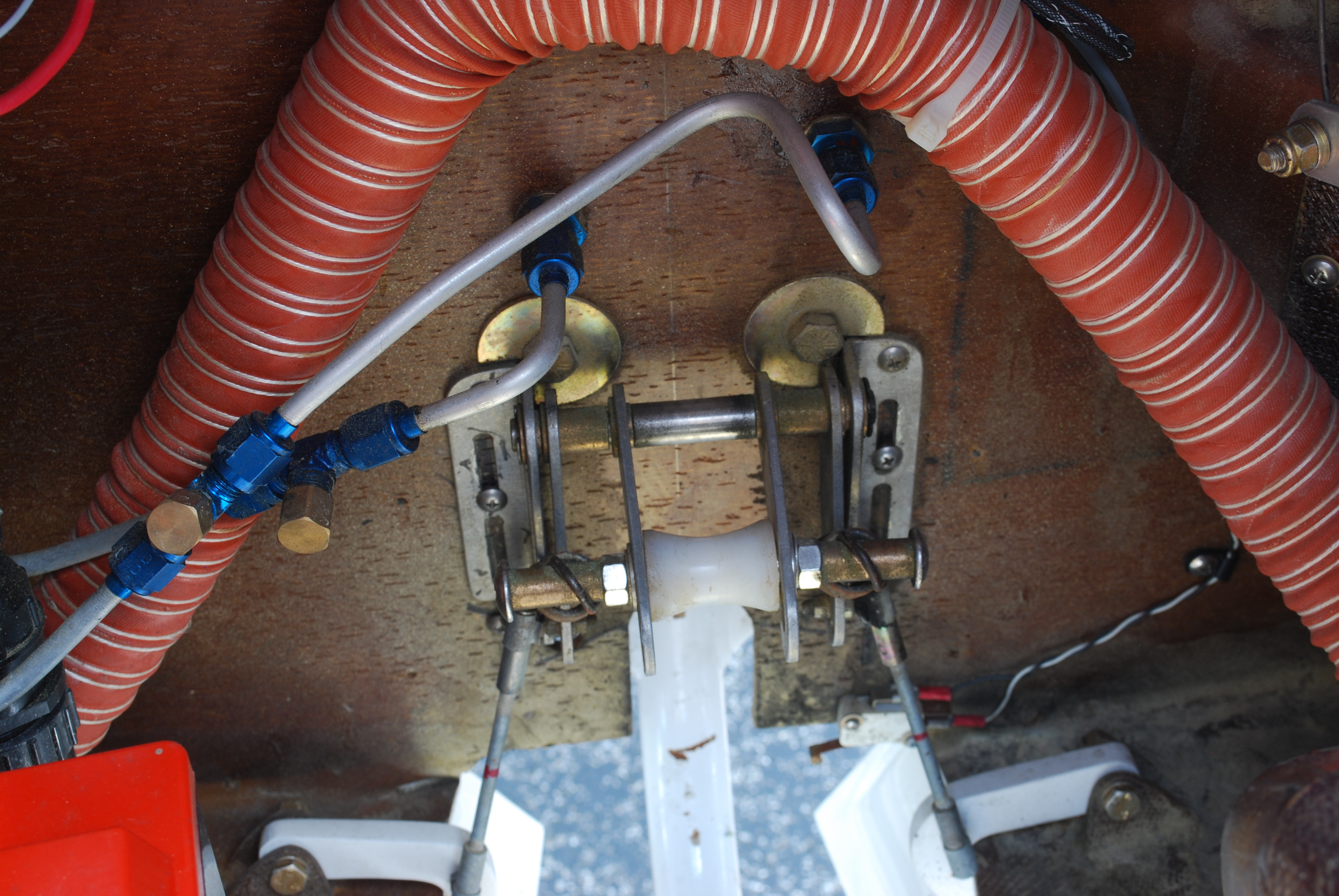
As soon as I raised the gear, I discovered the doors would close on the nose wheel. That’s because the linkage was too short. If I made them longer, the mechanism wouldn’t be overcenter when down… Unless I moved the actuator up.  So I did that (making new connecting rods wouldn’t be that much trouble). But once you move it up enough so that the mechanism is overcenter, the roller that rides on the gear leg becomes perpendicular to the leg. So now it becomes a stop. I asked Scott Swing and a couple other builders who used this mechanism how they got it overcenter and they all said they didn’t. No matter how much they tweaked it, they couldn’t get it to work properly when it was overcenter.

I decided to re-position the actuator so the doors would close properly and made stronger springs to hold the doors open. The concept of being overcenter is sound, but in reality, if the springs are not strong enough to overcome the force of the air on the doors, then they would never open far enough to go overcenter in the first place.

Next I discovered a problem that I ran into when adjusting my mechanism. I have to remove one of the rod ends to adjust the length of the linkage. This is a pain and you only can adjust it one turn at a time (which may be too much) and you can’t adjust it in position.

The next issue is that this mechanism is narrower than mine.  Because of that, the lower rod ends where beyond their allowable limits. The fix there was to rotate the rod end 90 degrees. But then the stud isn’t long enough to go through the gear door arm.

The solution to the adjustment problem is to use right hand threads at one end and left hand at the other.

Here’s what I did:

I ordered a pair of left hand threaded rod-ends for the bottom from McMaster-Carr.  I’ve never needed left hand taps before and they aren’t something you’ll find at Ace Hardware.  So I ordered those as well. Since I’ll be tapping blind holes, I ordered the set of left hand taps.  That way you’ll have the taper, plug and bottoming tap for just a couple dollars more.  I was going to order the left hand jam nuts but at McMaster you have to order 50 and it would cost about $10.  So I got six (two spares) from Spruce for about $3.

I made a new set of connecting rods with the top ends tapped for right hand threads and the bottom was tapped for left hand threads, I was almost ready to assemble everything. But there was one last step to be done. I flattened the rod in the middle to accept a 1/4″ wrench.

To attach the rod ends to the door arms, I drilled and tapped another piece of 1/4″ rod stock and cut them about 1/2″ long.  Then I drilled out the existing holes in the door arm to 1/4″, sanded the rod pieces, coated them with epoxy and inserted them in the door arm holes. Once the epoxy cured, I filed them flat.

Before screwing in the rod ends, I used some loctite to keep them from coming loose.

2017-02-08 IMG_20170208_130407 2017-02-08 IMG_20170208_130413

I used a couple of thick washers to move the rod end forward. I was hoping that would be enough to get the mechanism overcenter. But it wasn’t.

Once I got everything assembled I didn’t like how close the actuator was to the hydraulic line coming out of the canard bulkhead.  So I ordered a close clearance 90 degree fitting and rerouted the hydraulic line.

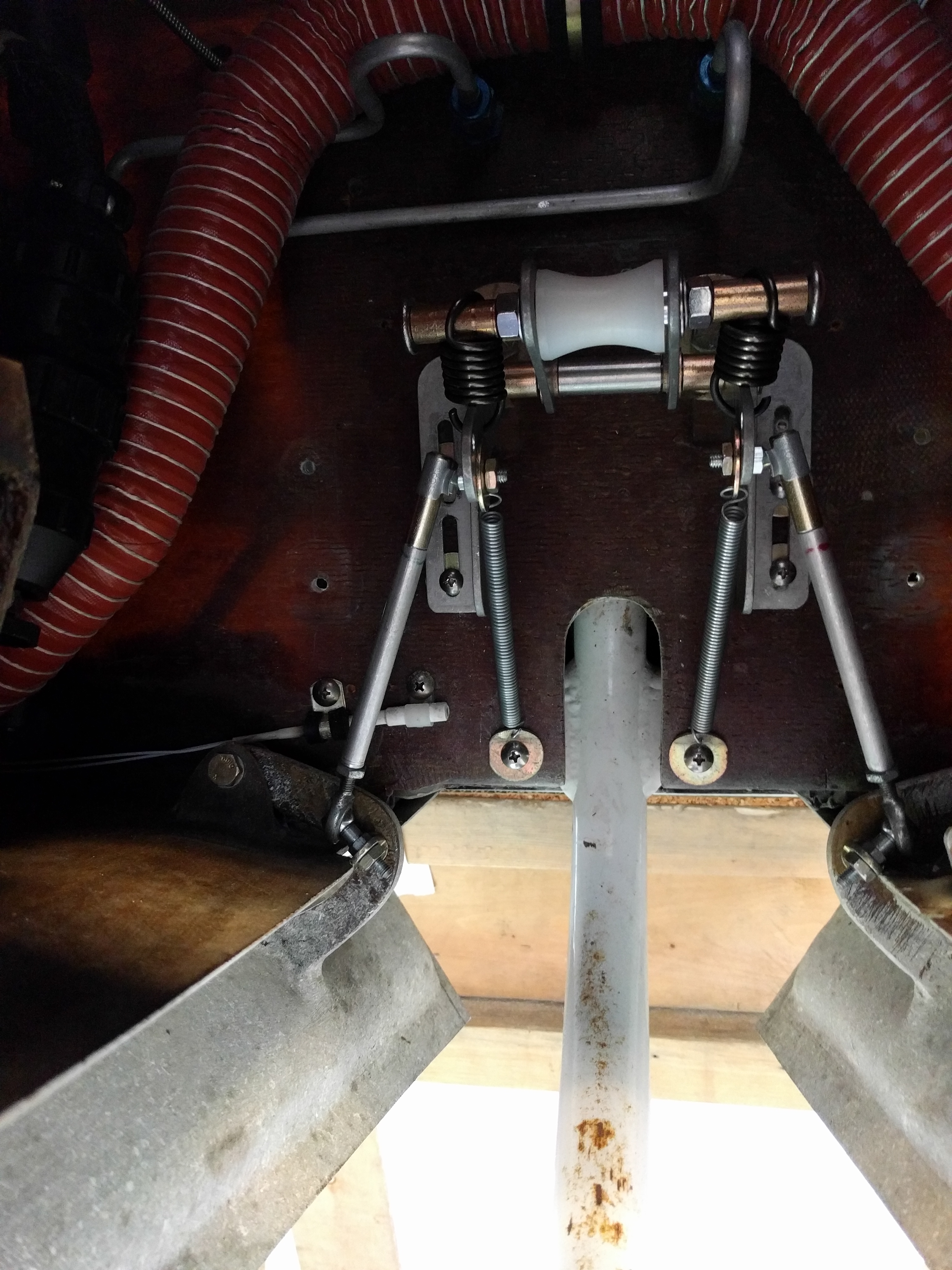
Here’s the current setup:

2017-02-14 IMG_20170214_145935 2017-02-14 IMG_20170214_145956

One the test flight, everything to worked fine. Except for the burning rubber smell. So I need to tweak the adjustment a bit more.

Change suggestion:

If you’re going with ANY mechanical door actuator, move the rear door arms forward about 3-4 inches.  They are where the manual has them to accommodate the hydraulic door actuator. But if you’re using a mechanical actuator, if they were just a bit forward then you could easily get the linkage overcenter.



7-99 Sealing the Nose Landing Gear

This entry is part 39 of 39 in the series 07 - Landing Gear

One of the biggest comfort issues with the Velocity is heat (or lack thereof). There are numerous methods of increasing the amount of heat entering the cabin.  I won’t go into that here.  Beyond that, the reason for lack of a warm cabin is that the retractable gear Velocity’s are drafty.

In a Velocity with retractable gear, there’s a big opening in the front for the nose gear.  While there are doors which cover this opening when the gear is retracted, it’s not airtight. And when the gear is extended, the volume of air entering through that opening is impressive.

The area under the doghouse at the leading edge of the canard is open to the nose, and all of the air entering the opening for the nose gear. This is the primary path for outside air into the cabin.

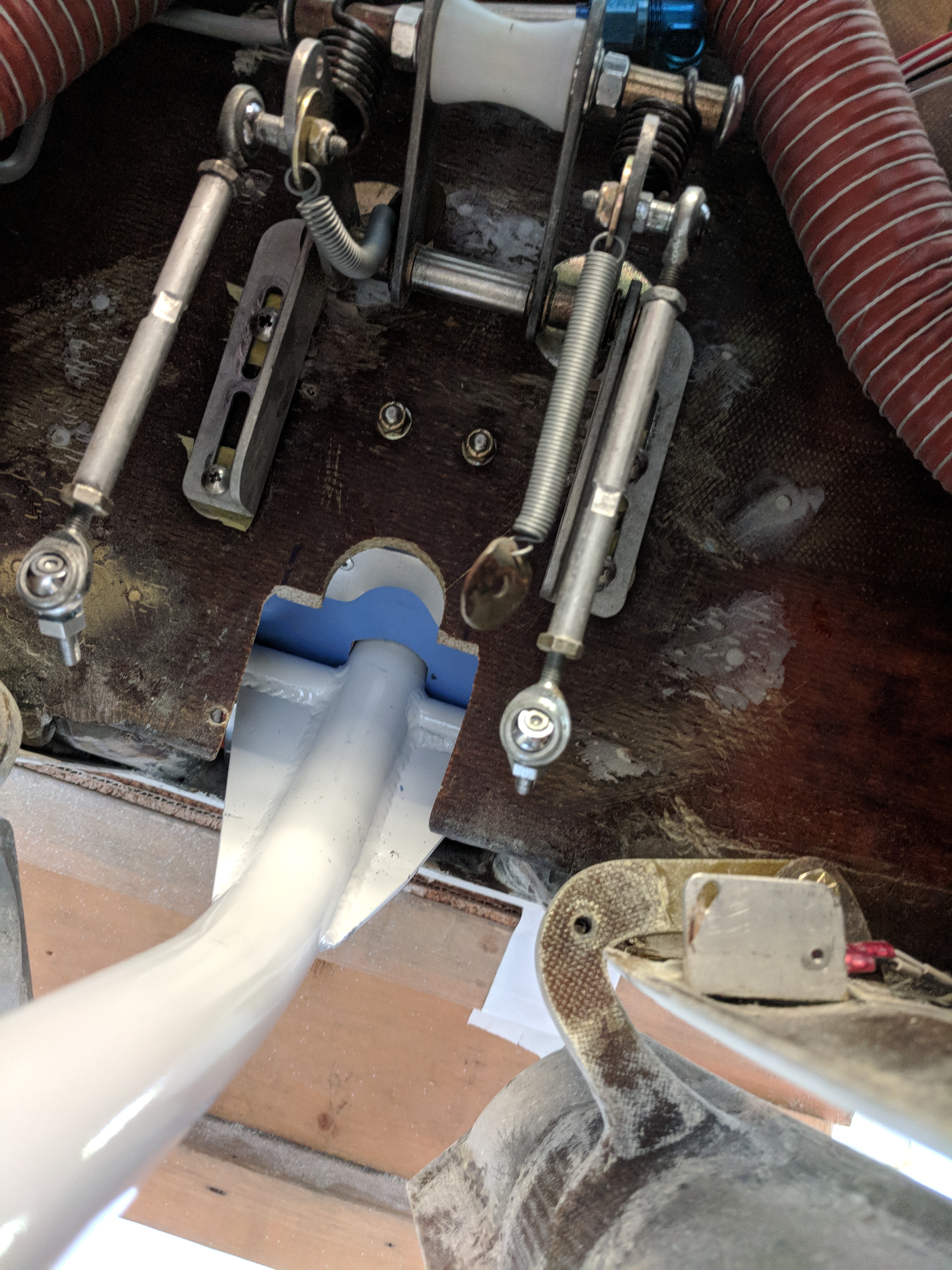
Second, that nose gear opening extends aft of the canard bulkhead. Which means air is infiltrating into the keel.  Directly above this opening is where the elevator push-pull tube exits the keel into the cabin.  Some people have fashioned boots to seal the area around the push-pull tube to block this path of outside air entering the cabin. But even then, there are numerous paths from the keel to the cabin.

The final path for outside air getting into the cabin is through the openings for the rudder pedal push rods which go through the canard bulkhead to the bellcrank.

When I extend the landing gear, I am greeted with (literally) a blast of air.  In the summer, it’s welcome.  In the winter, not so much.

Blocking the primary air path has been solved for quite a while by creating an upper bulkhead between the leading edge of the canard and the top of the nose. What I will be addressing is stopping the air through the second and third paths.

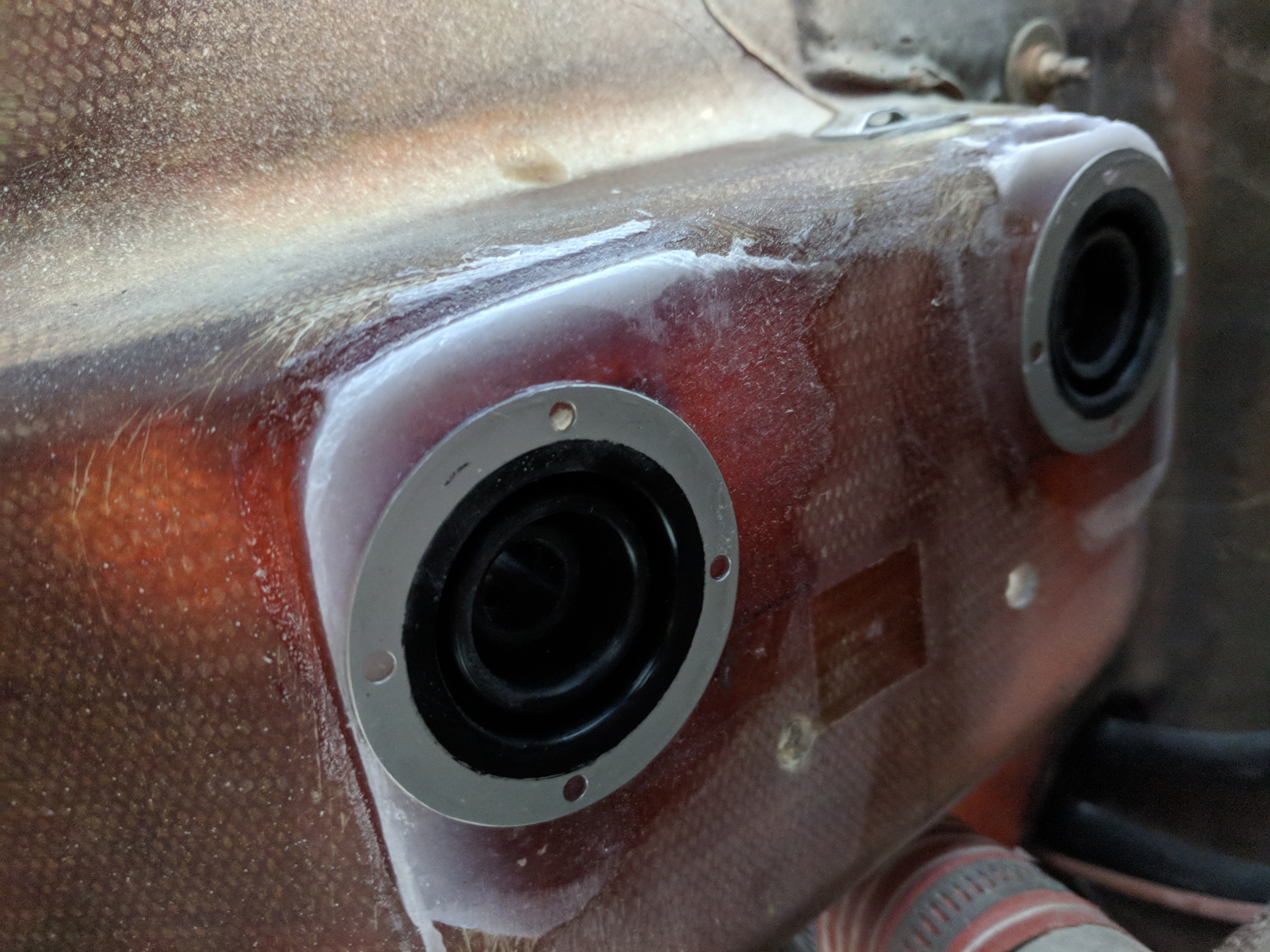
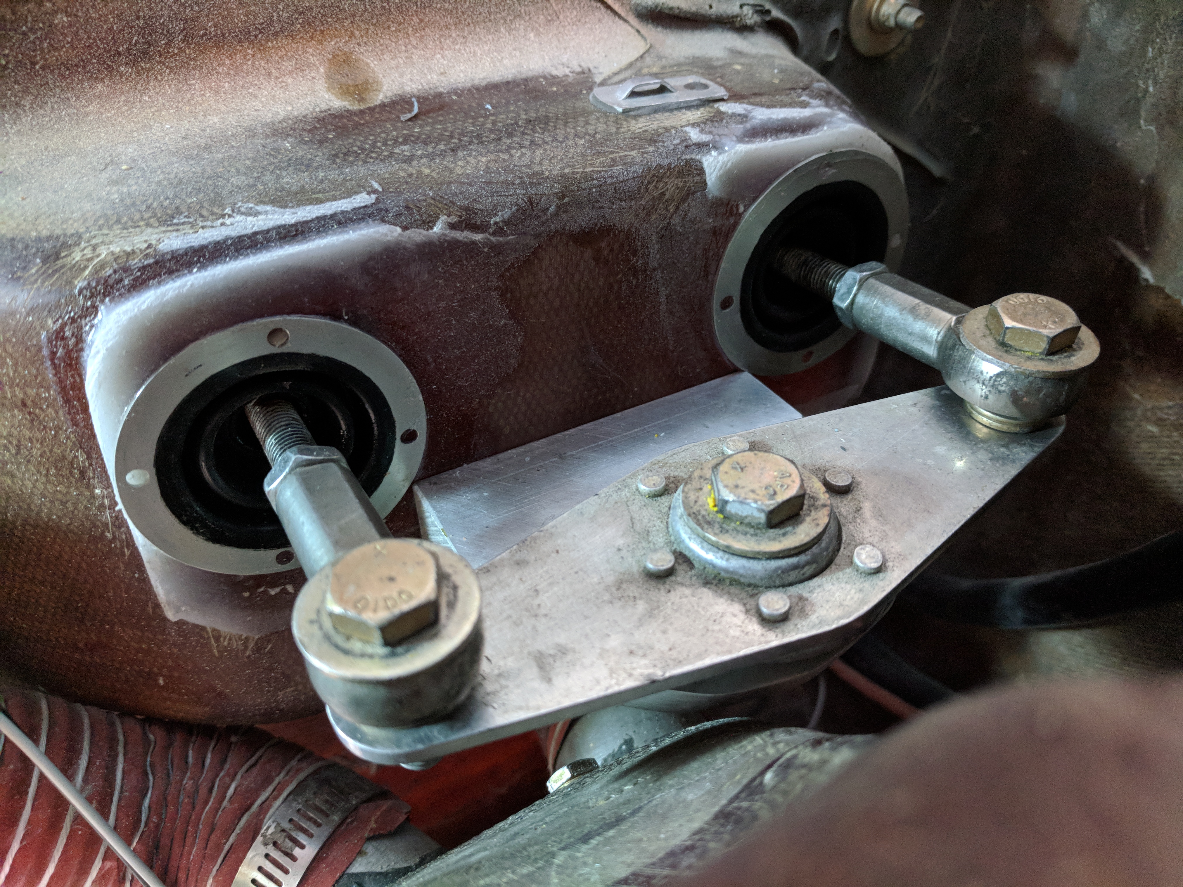
For the rudder pedal pushrods, the factory has been using a box which covers the area on the forward side of the canard bulkhead.  I couldn’t use this approach as my oil cooler exit duct if closer to the canard bulkhead than the plans call for.  Fortunately, fellow builder and problem solver Andy Millin came up with a solution.  Grommets (which I would call small bellows type seals). One for each pushrod. These are available from McMaster-Carr for about $15 each.  The part number is 9280K62.  Andy says this can be done with the canard in.  My canard was out for service which made the job much easier. Once I had removed the pushrods and bellcrank, I had to enlarge the holes to accommodate the grommets.This created a bit of a challenge because a hole saw would be the perfect tool.  But the rudder pedals were in the way from the cabin side and the oil cooler exit duct was in the way from the nose side.So here’s what I did:  I took the hole saw bit and put a ratcheting wrench on the hex shaft.  Then a large area washer went over that to give me a larger bearing surface. Wedge the whole thing in position and start turning the wrench.  In just a few minutes, I had two perfectly sized holes.

Hole saw rig:

IMG_20180328_075112 Cutting the holes:

IMG_20180328_075142

The next task was creating a flat surface for the grommets. Now I could have just globbed on the RTV and stuck them in place. But the holes where close to the edges and I didn’t want any chance of air leaking through.  So I took a piece of ¼” aluminum stock that I had, waxed it up, applied some Resin Research epoxy with cabo around the holes and clamped the aluminum in place. The next day, I removed the aluminum, cleaned up the holes and then I was ready to install the grommets.

Ready to install the grommets:

IMG_20180328_141409
I could have used screws to install the grommets, but as there is very little tension on the grommets, I used RTV.  Once the RTV cured, I cut the tips of the grommets off and reinstalled the rudder pushrods.


Grommets installed

IMG_20180328_142235

View from the cabin side:

IMG_20180328_142256

Rudder pushrods installed

IMG_20180330_144417

Blocking the air coming through the keel has always been a challenge.  Some have made a boot similar to those found on manual transmission shifters. Over the years, I’ve considered a couple approaches.  The one that I was most hopeful of was similar to what is found on many automatic transmission console shifters. Basically a slotted housing with a flexible, wide area washers.  But because of the size of the opening, I would need multiple wide area washers with slotted openings and that would require guides on the housing.  If I was still in the building stage, I would have explored that further.  But I wanted to get back in the air.  So I went with Plan A.

I had thought about this approach while still building but I abandoned it to get finished. Basically, it’s a pair of supports with baffle material being the final seal against the pivot shaft.  The disadvantage to this method is that there is a gap while the gear is in transit. But when the gear is up or down, it should provide a very good seal.  I took measurements and built up the concept in CAD to get the dimensions and validate the concept.

Here’s what it looks like:

output_jiQWdO

There are two rigid components.  The upper (canard) and lower (floor) brackets.  One thing I did NOT want was one of these coming loose and preventing the gear from extending.  So on the canard bracket, the two center mounting holes go through the canard bulkhead with MS27039 screws and locknuts. Since there’s no way to do through-hole screws on the floor bracket, I used 5 T10 screws.

bulkhead floor

The material for the brackets is 1/8” aluminum.  This is a bit of a challenge to bend, but I didn’t want any possibility of it deforming.  The flexible material is standard 1/8” baffle material which is cut trial-and-error to get a tight fit against the gear leg in the retracted and extended position.

NOTE: I do not think it’s possible to install these with the canard installed. Also, the brackets are a little oversized.  They will require some trimming to fit.  This is intentional since you want a very tight fit to the sides of the keel.

In the first version, I attached the baffle material to the bracket using pop rivets. But I noticed buckling.  So on the second version, I used 1/16” aluminum stock as a backing surface.

I planned on using RTV to fill any gaps between the brackets and the keel but decided to try it out before doing that.

Gear up.  I could have made the floor baffle a little tighter, but then I would run into binding when the gear was down.

IMG_20180420_155938

Gear down.  Very tight fit all around.  And that’s when it is really needed.

IMG_20180420_160014

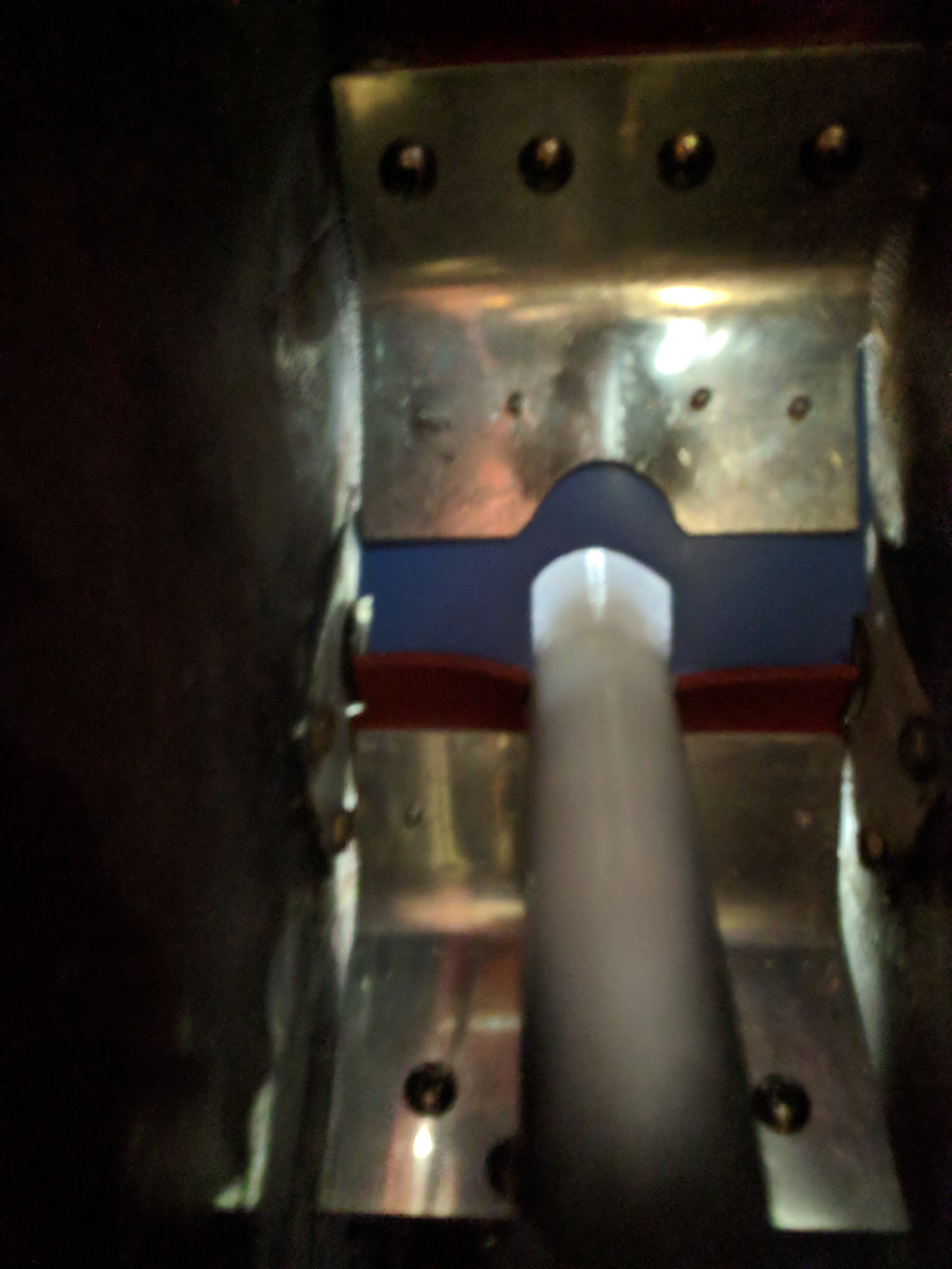
View from inside the keel with the gear up.  A little bit of gap here, but I’m more concerned with when the gear is down.

IMG_20180420_155928

On the first flight after installing, when I lowered the landing gear, I was a little alarmed at first because I thought the gear wasn’t extending. There was no familiar rush of air when the gear was extending. Before, I could always feel a strong breeze around my lower legs.  Now, the only indication that the gear is down is the drag of the gear and the wind noise from the gear hanging out in the air.

I’m going to have to wait about six months for cold weather before I can claim total success. But at this point it feels promising.