12.2.2 Fuel Line

This entry is part 42 of 50 in the series 12 - Engine / Propeller

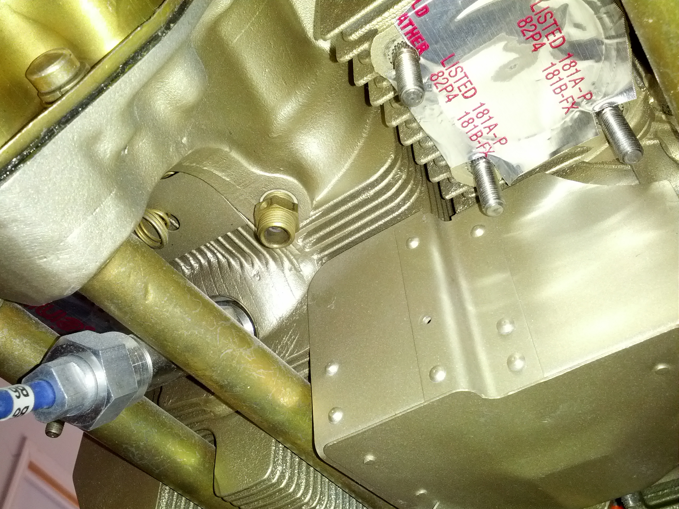
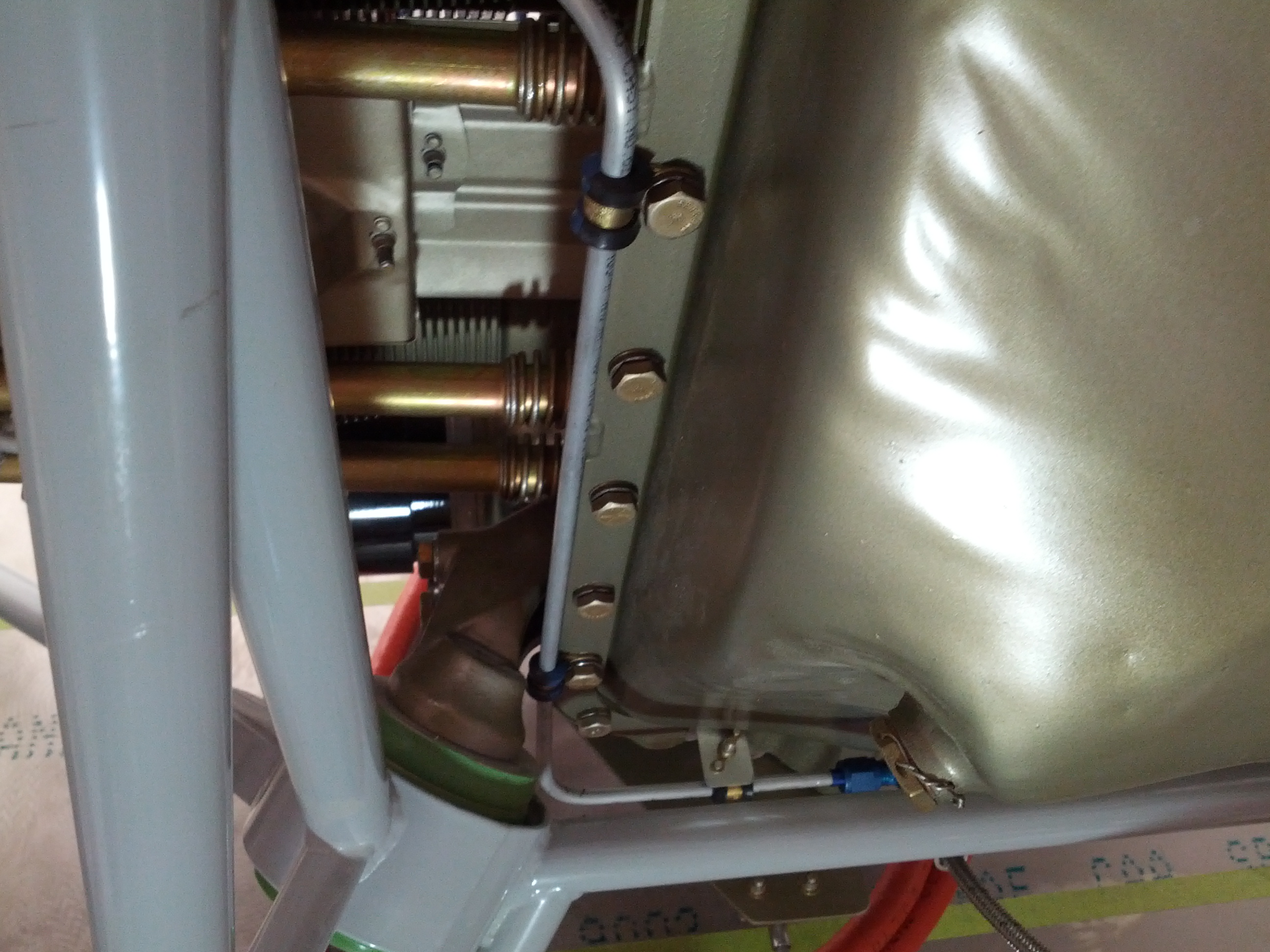
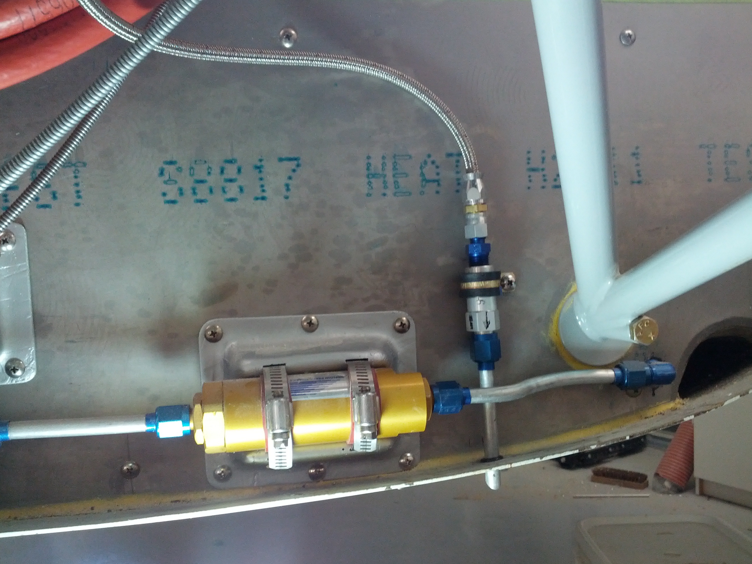
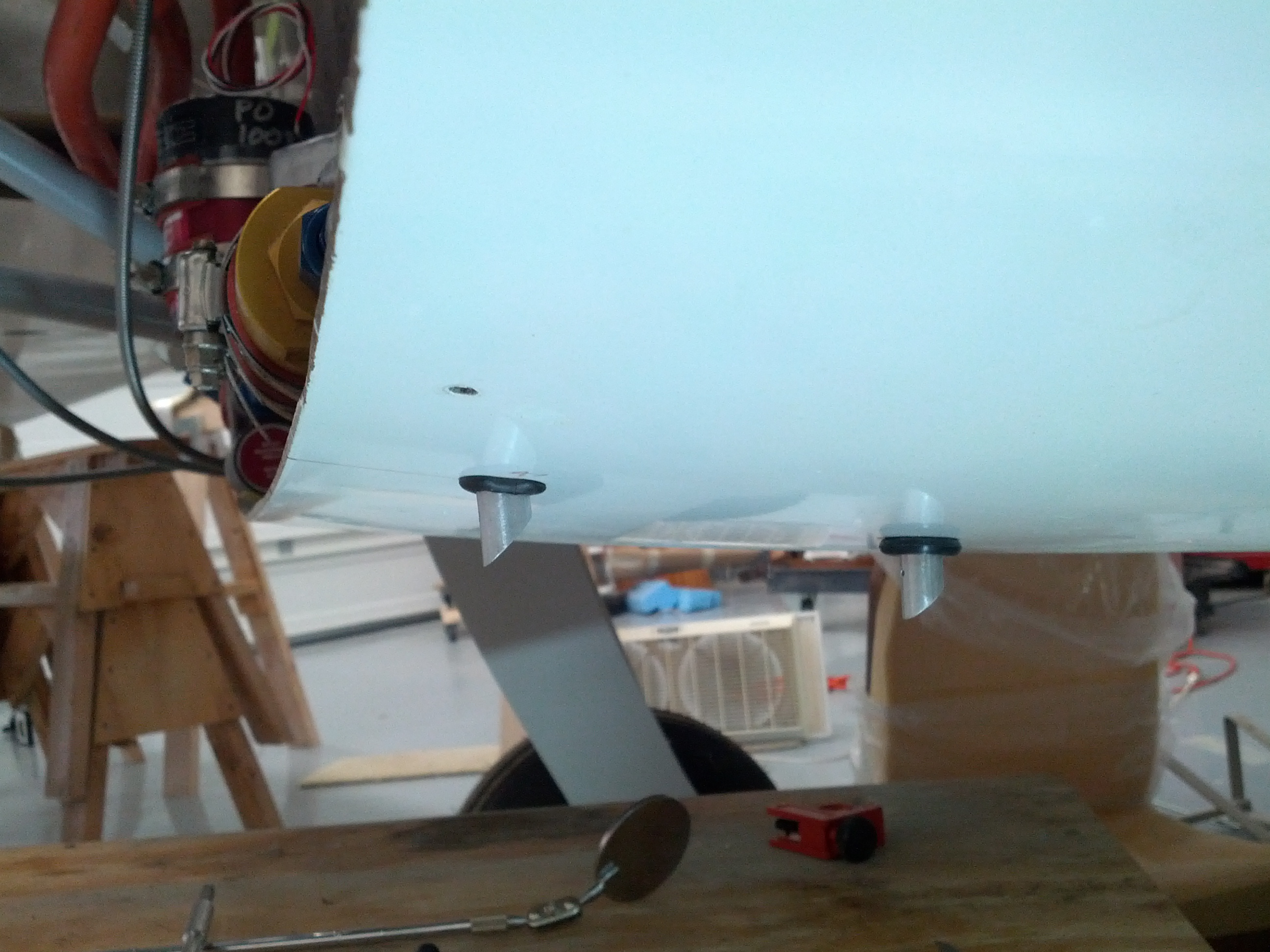
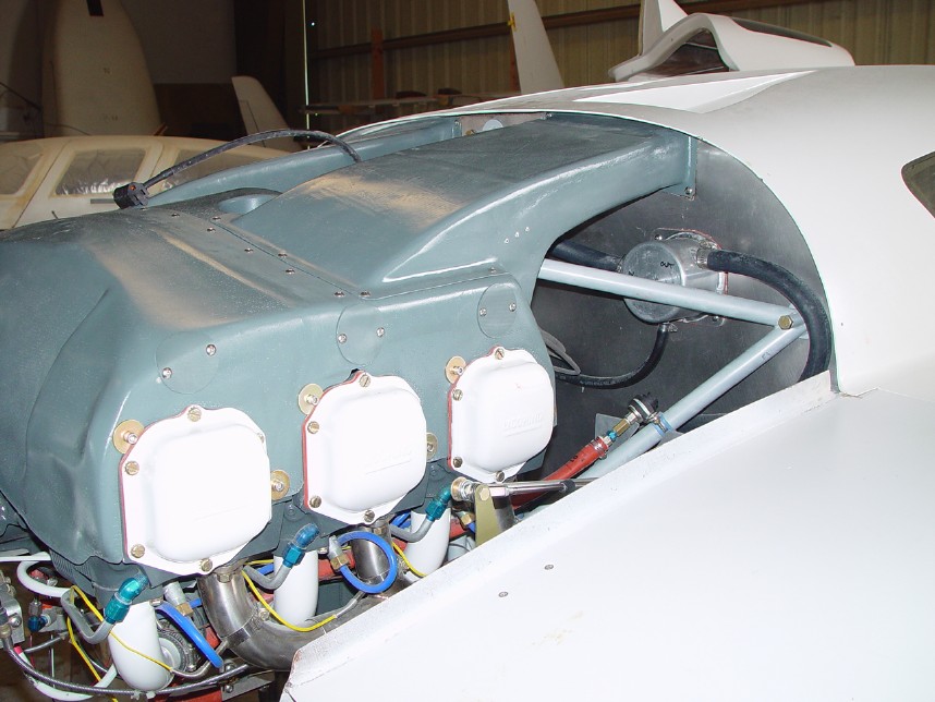
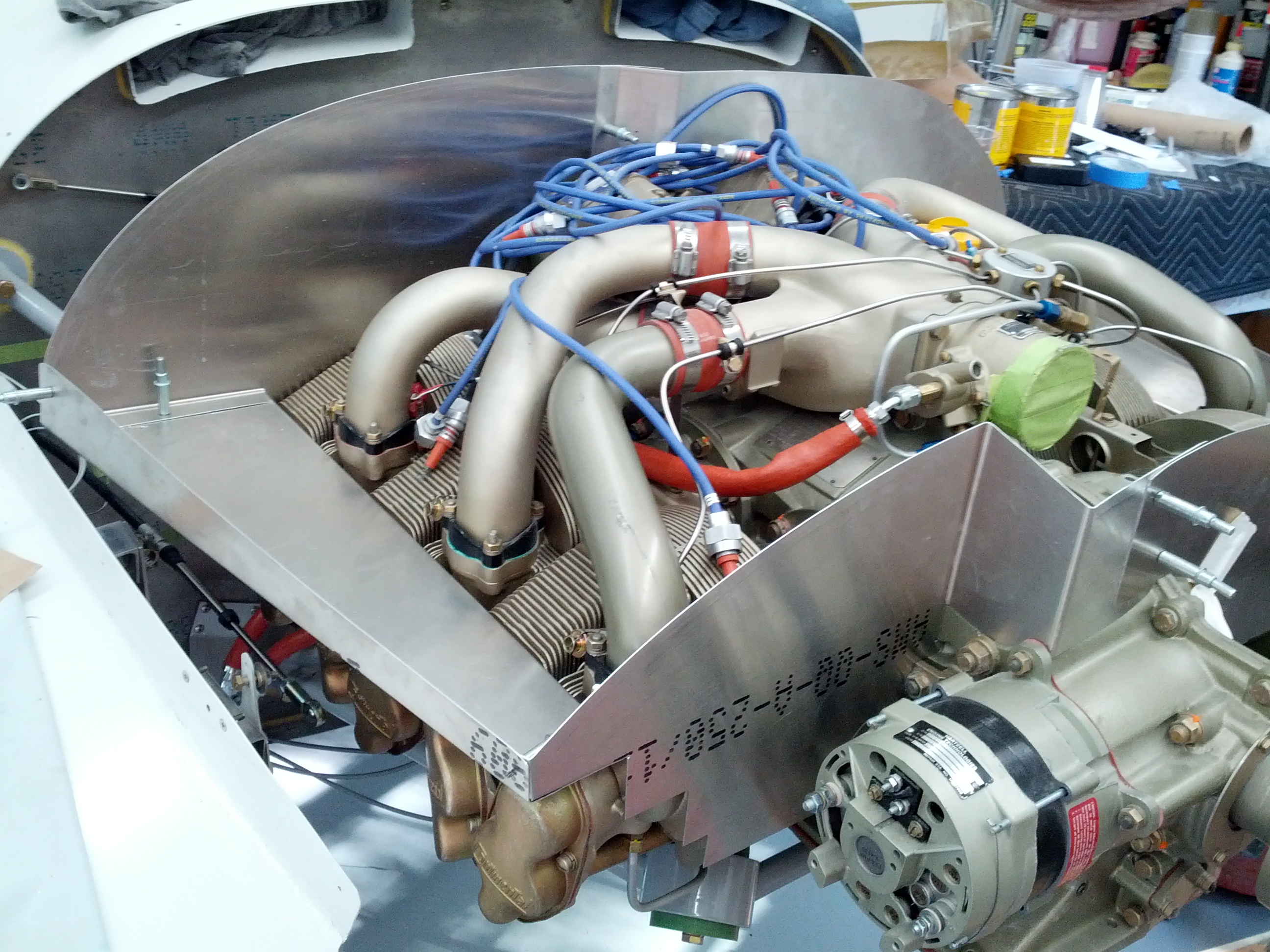
Looking back from the firewall. The mechanical fuel pump is on the right. Oil filter is on the left. I put a fuel fitting on to see if there was enough room just for the fitting.

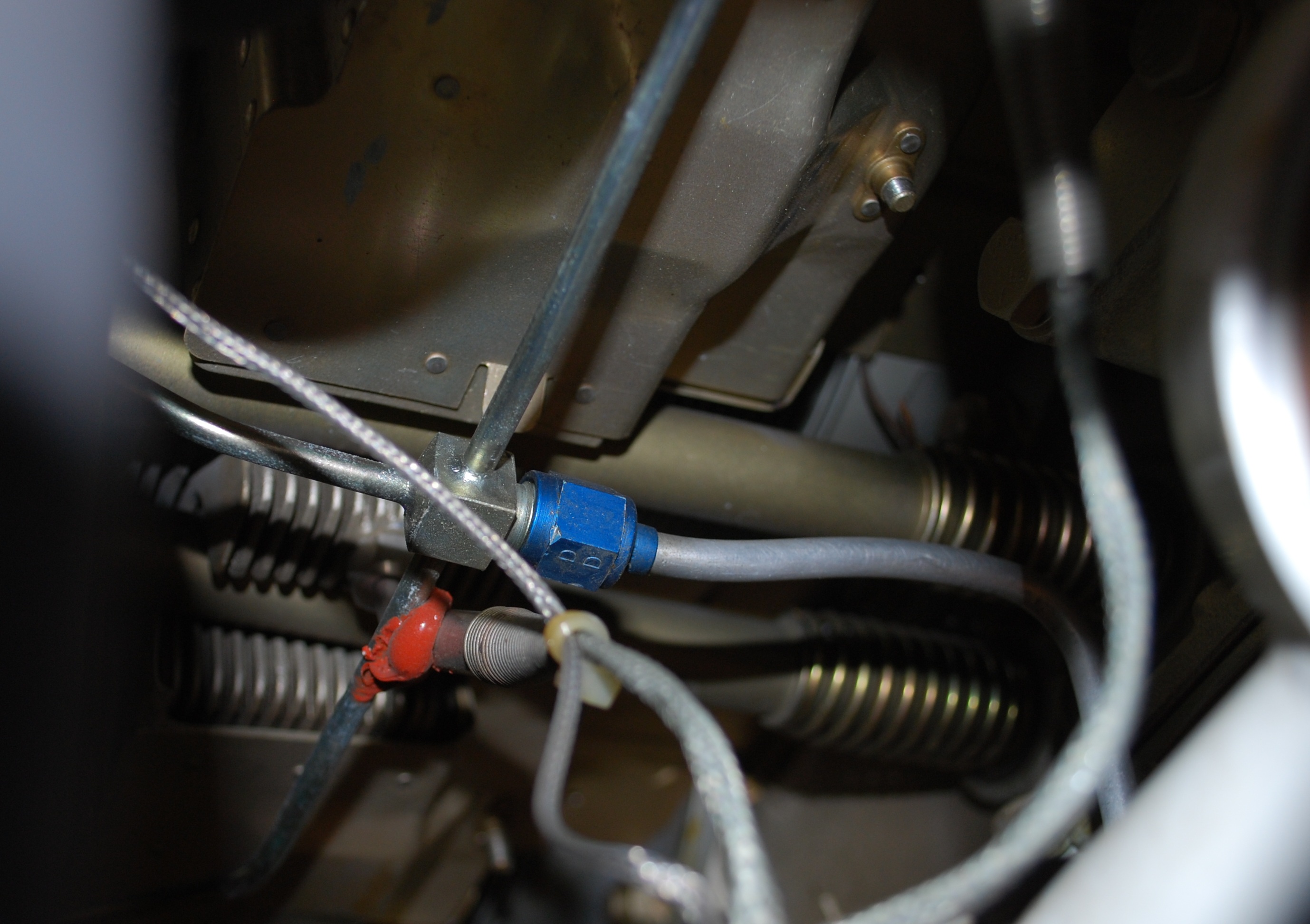
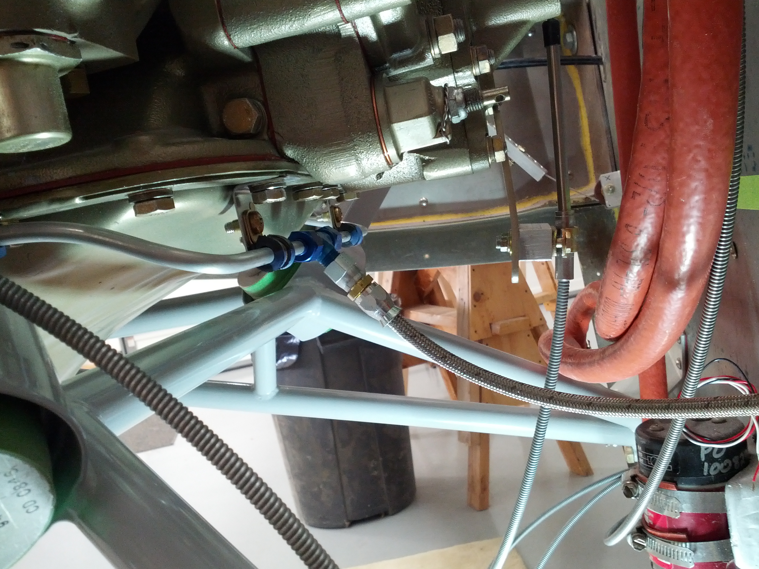
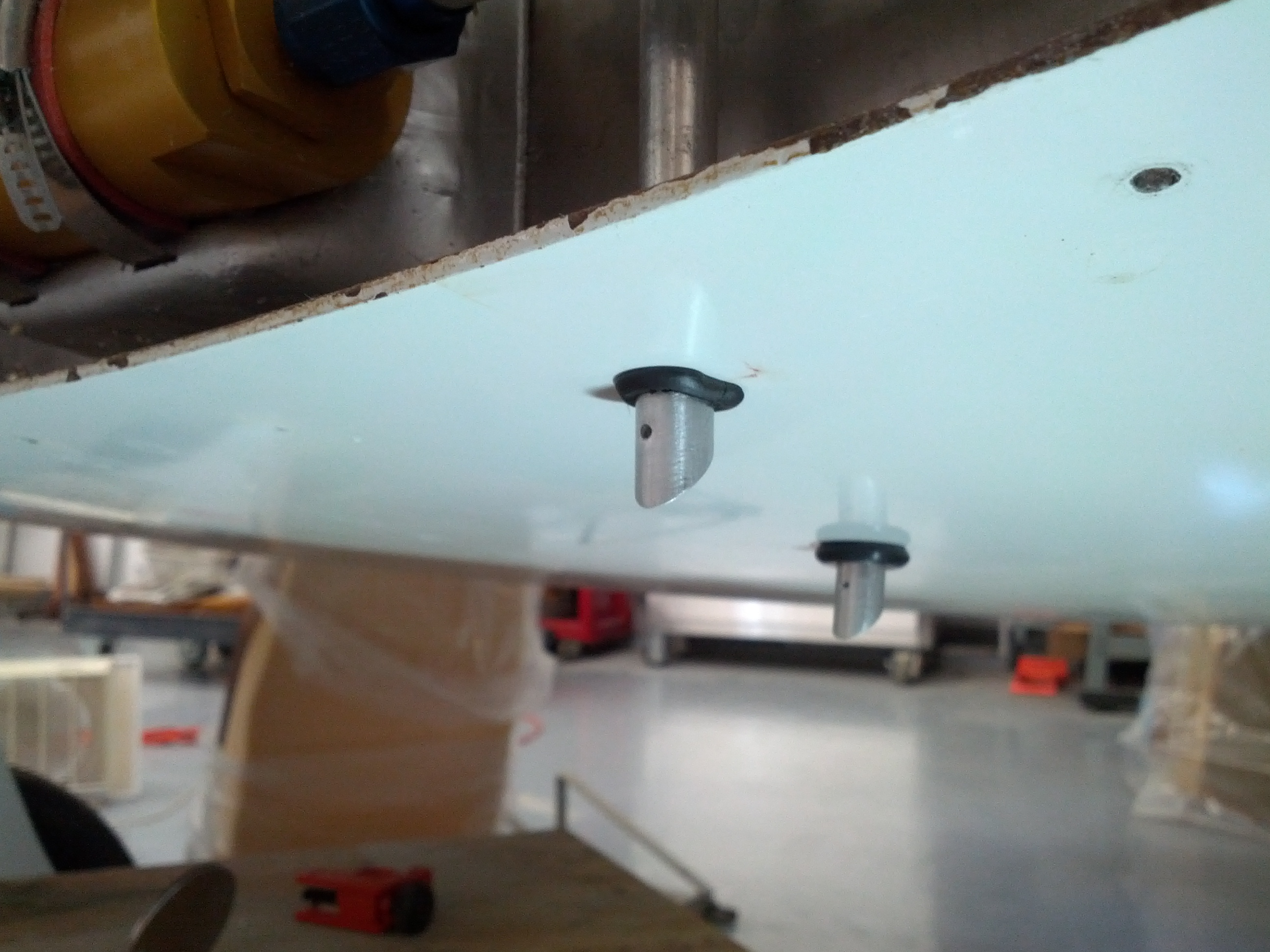
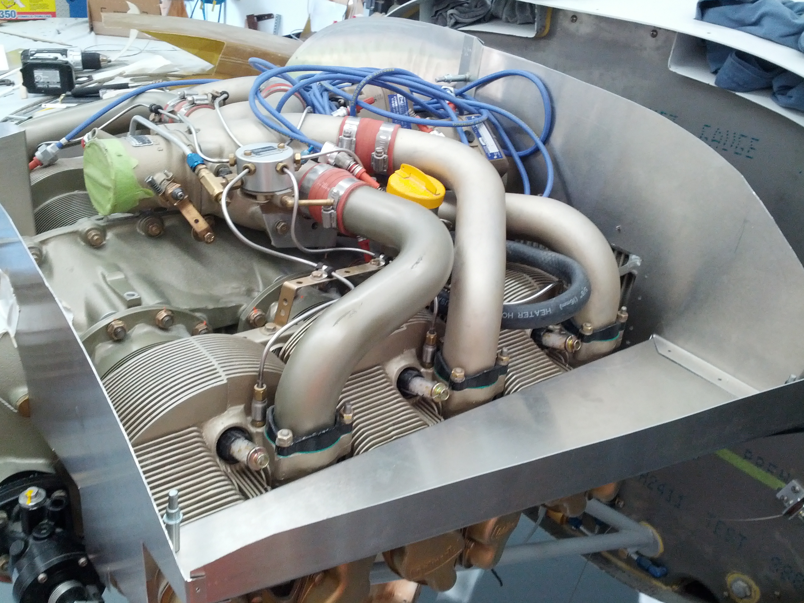
The same view from a little farther away and higher.


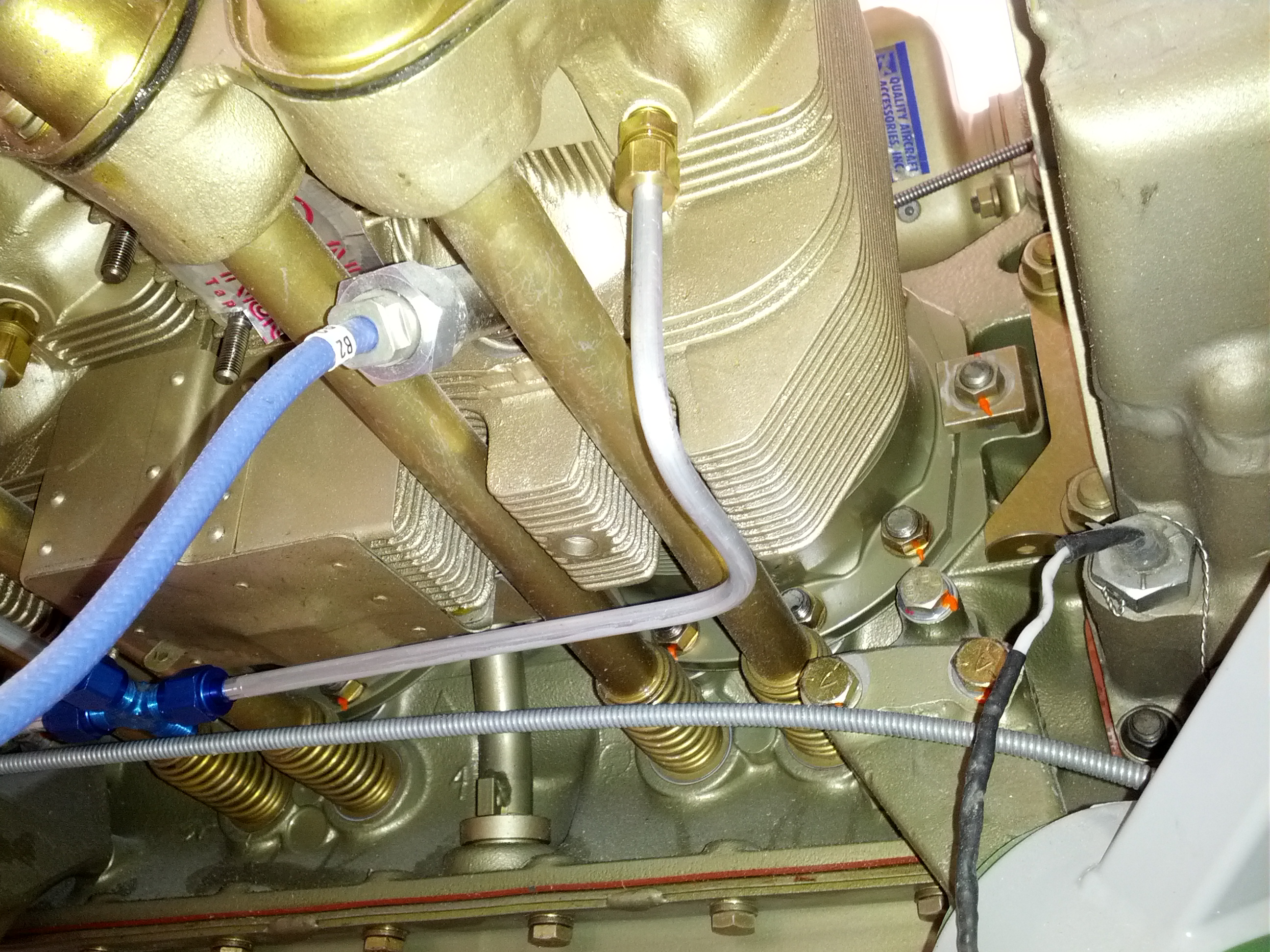
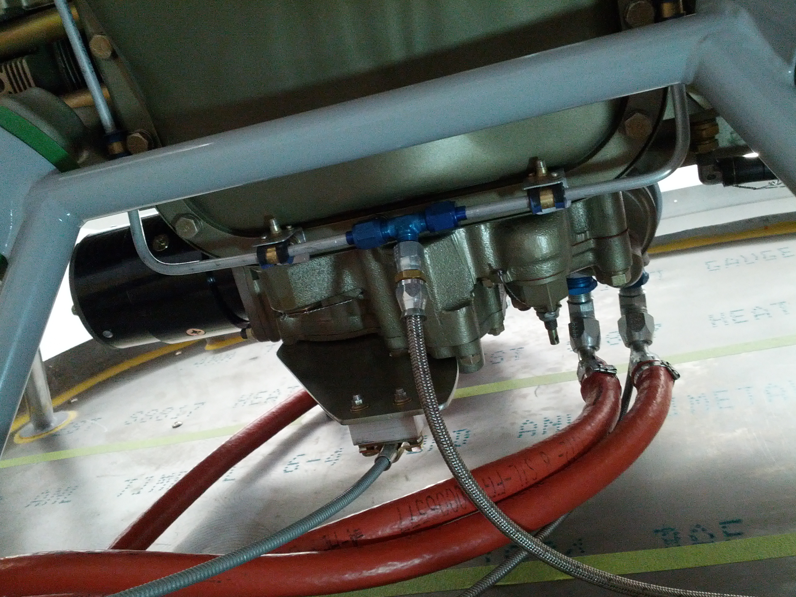
Looking down from above. You can see the firewall and fuel filter on the right. The oil filter is on the bottom. And you can see the (out of focus) fuel supply line on the right.

So the question is, do I leave it as it and route the fuel line up between the oil filter and fuel pump? Or do I try to rotate the fitting at the fuel pump so I can route the line forward of the engine?


12.2.1 – Aluminum Oil Lines

This entry is part 20 of 50 in the series 12 - Engine / Propeller

The aluminum oil lines from the nose oil cooler have been in for a while. But I couldn’t install the flex lines to the engine because I needed to install the sandwich plate on the engine which provides the inlet and outlet for the oil to the secondary (nose) cooler.

So I drained the oil, removed the filter and installed the sandwich plate.

Then I got the 1/2″ braided, stainless steel flex lines and cut them to length. We figured that straight fittings were not going to provide good routing for the oil lines so I bought four 45-degree fittings. I installed one on each flex line, slide the firesleeve over the line and then installed the fittings on the other ends. I finished up by clamping the firesleeve to the fittings.

At Malcolm’s insistence, I purchased 4 “Del Seals”. These are little washer than go inside flare fittings. They insure a good seal between aluminum and steel fittings. So I then attached the oil lines to the firewall fitting.

Attached at the sandwich plate.

Then the new (shorter) oil filter was installed.

12.2.3 Cylinder Intake Drain Lines

This entry is part 19 of 50 in the series 12 - Engine / Propeller
This one is a good example of the… challenges of building an airplane. I started working this particular task almost a year ago.

Technically, the Velocity is a “kit”. Which means that I should get a bunch of parts and then assemble them into an airplane. With a “plans built” plane, all you get is a bunch of paper. From which you build (or acquire) every single component. Even though the Velocity is a kit, that doesn’t mean there aren’t some of the same challenges that “plans built” folks have.

On the Continental IO-550 engines, each of the six cylinders has a drain. This allows excess (unburned) fuel to drain out of the cylinder at engine shutdown or if the engine is over-primed prior to start. These six drains have to be merged into a single line which then goes through a “sniffle valve” (I kid you not) that allows fuel to exit but does not allow air to enter. After the sniffle valve the line exits the bottom of the fuselage.

Here’s the section of the manual that describes this part of the build:
The intake manifold on the Continental has 3 separate 1/4” lines on each side of the engine coming from each cylinder heads to a manifold. From here we need to make two hard lines that join together at the back of the engine at an AN824-4D Tee fitting. After a short run from the AN824 you will switch to Mil-H-6000 line. Before the drain exits the cowling you have to connect to a short run of 1/4” aluminum line that is
flared at one end with an AN818-6D and an AN819-6D. Screw in an AN815-4-4D fitting into your 1H19-6 Cylinder drain valve. This is provided by Continental. Attach you line to this and route the drain valve out the bottom of the airplane.

Okay, pretty straight forward. First, I need this drain valve. I looked on and off for almost 6 months. I got a number of different part numbers but still couldn’t locate one. Finally, I got a lead at Global Air Parts and was able to pick one up.

Now I just need to run the two lines from each manifold to the tee. Except that I DON’T HAVE A MANIFOLD. Nor do I have the lines coming out of each cylinder going to this “manifold”. At the bottom of each cylinder I have a fitting. And that’s it.

I asked my A&P to call me the next time he had a Cirrus (or any other plane with an IO-550 engine) in the shop so I could take some pictures. Within a couple of months, I got a call that a Cirrus was in the shop so I headed out with my camera.

Here’s a picture of the three cylinder drain lines meeting at the manifold with a 1/4″ flare fitting.

Well, I can’t make THAT. So now I start looking for a pair of these things. But are they engine parts or airframe parts. Everyone I spoke to said “Airframe Parts”. Which mean they are available from Cessna, Cirrus, Piper, Beech, etc. This typically means insanely expensive. For example, the sniffle valve cost me $265.00 (used).  So I check with all the used parts sources and I can’t find anything. When I went to Oshkosh this year, I looked at every single IO-550 that I could find. Most had the drain lines like the Cirrus. But a couple had homebuilt lines.

So I made the decision to fabricate my own. I went over to the AeroMart where all the vendors sell everything that you can think of and picked up a bunch of AN fittings.

When I got back home I decided to run the idea past my A&P, Lynn of Motive Services, to see what he thought. Lynn is my go to guy when I have a question about acceptable practices, best methods, is it legal, etc. He did some digging and discovered that the “Tube assembly, Cylinder drain” is actually a Continental part (PN 643584). With a price of about $200 each. Since this is a drain line, not under pressure and will only see fuel if the engine is over primed or after it’s shut down, I decided that fabricating it was acceptable.

So I got the tubing bender, flaring tool, compression fittings and got to work.

Here’s the tube from the #6 cylinder.

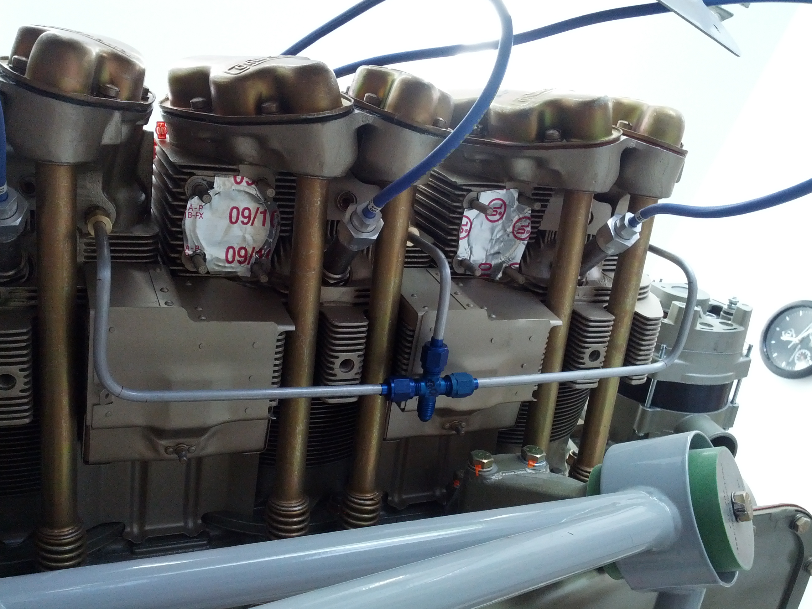
Here are the odd cylinder drains run into a 4-way AN fitting

Now I need to run a line to the front of the engine to meet up with the even cylinders drain line. The bending on these lines was a little tricky because there were a number of directional changes. This is the stuff that Malcolm excels at.

Odd cylinders drain line running forward.

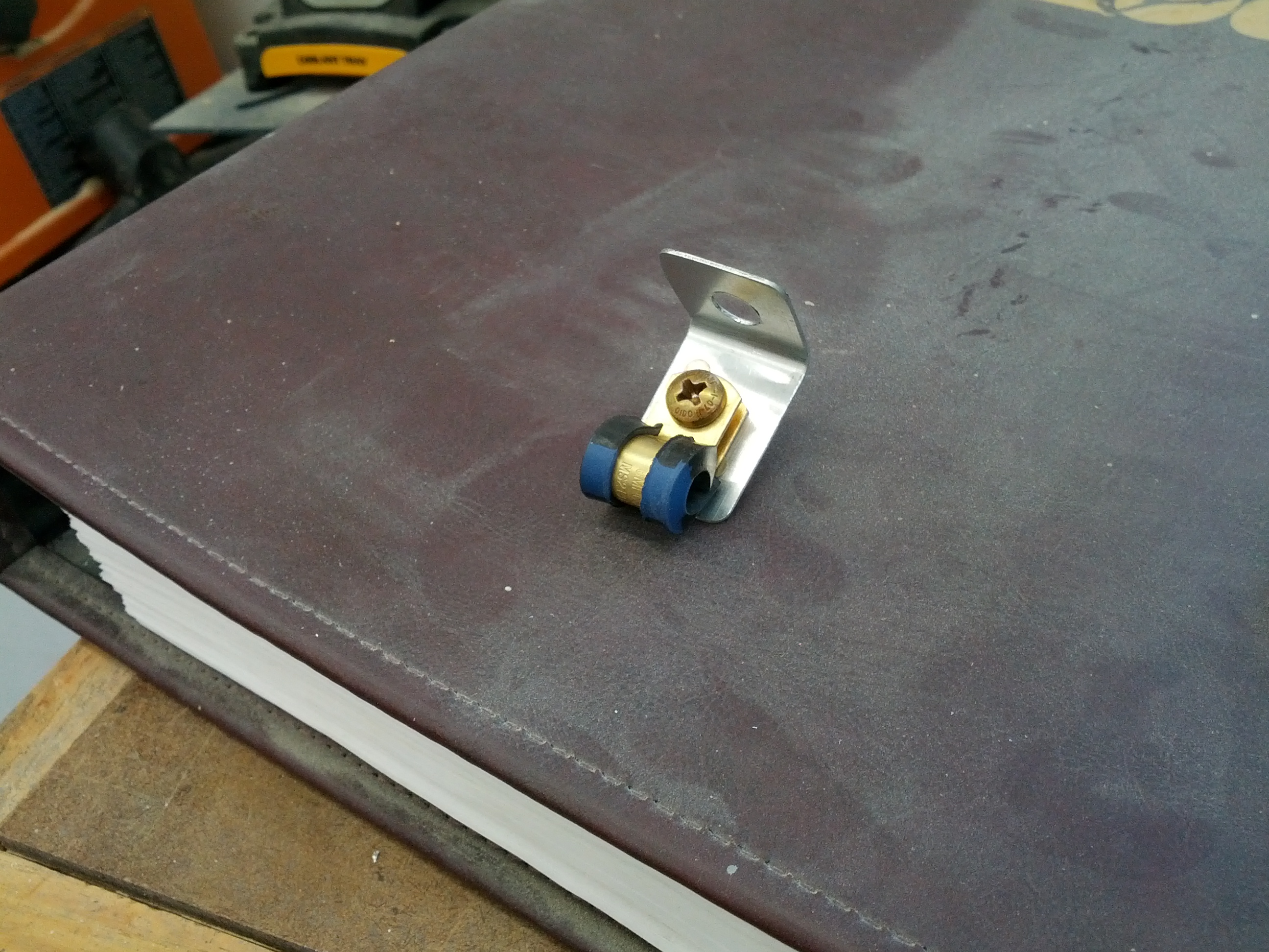
At the front of the engine, I had to drop the line a bit to clear some components of the engine. So I had to make a standoff for the Adel clamp.

Then the lines from both sides meet at a “T” fitting.

From the “T”, I made up a braided steel hose that would go to the firewall. The manual says that unshielded rubber hose is okay, but I like using the braided line. Since it’s not in use during engine operation, I don’t think firesleeve is necessary (I’ll check with Lynn to be sure).

Looking up from the bottom at the front of the engine.

I mounted the sniffle valve on the firewall and attached the other end of the braided steel line to it. I’m thinking about putting a 90 degree fitting on this end so the hose has better routing (I’ll put another clamp on the line later once I’ve changed the fitting).

And finally, I ran a short length of 1/4 aluminum line from the sniffle valve out the bottom of the fuselage.

12.3.4 Cooling Plenum

This entry is part 21 of 50 in the series 12 - Engine / Propeller

Cooling a rear mounted engine is a bit trickier than a front mounted engine. With the traditional front mounted engine, you put a couple of openings at the front of the cowling and let the propeller push the air into the engine compartment. Then the air is forced down through the cylinders and exits out the bottom of the cowling through cowl flaps.

The Velocity uses a pair NACA Submerged Inlets (or ducts) on the top of the fuselage to provide airflow into the engine compartment.  Unfortunately, the ducts supplied by the factory aren’t true NACA’s. They have some minor deviations which reduce their efficiency. But they should be good enough. If I had to do it again, I would take the Andy Millin approach and build them myself from scratch.

The air from the NACA’s is ducted into a plenum. This plenum is basically a fiberglass box that is fitted to the engine.

This is a picture of Rich Guerra’s finished plenum and ducts. Rich is running a different engine, but you get the idea.

I have four problems with this: 1) Every other piston airplane I’ve seen doesn’t have a plenum. They use the engine cowling to create the plenum. 2) When you have to service the engine, you have to remove this plenum. 3) With the plenum so close to the engine, it will be very difficult to distribute the airflow evenly over all the cylinders and 4) I’ve already had to modify the cowling to give the engine enough clearance in three places. This means that I’ll now have to modify the plenum too.

So after a lot of discussion with Malcolm and Lynn, I decided to wander way out into left field (or come in from left field) and go a more traditional route and use the cowling to create the plenum.This will require a sheet metal baffle that will seal against the cowl.

I looked into buying a set of baffles from Cirrus or Lancair (both use the same engine I have) and then modify it for the Velocity. But that was WAY too expensive. So I bought a couple of sheets of aluminum and some construction paper and got to work.

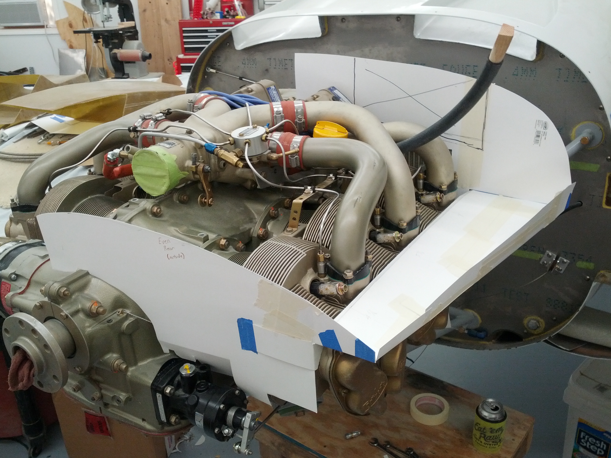
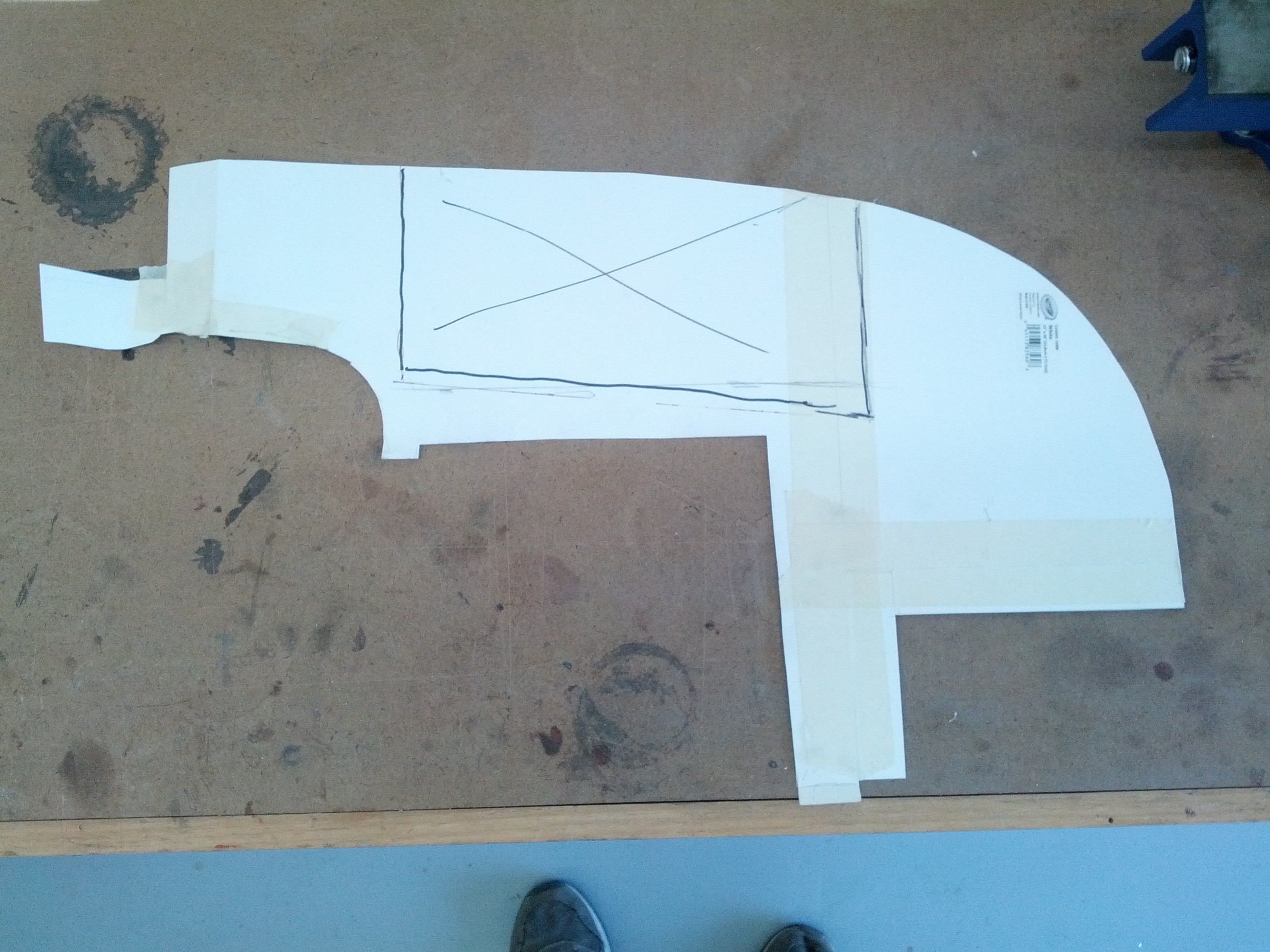
Here’s after building up the copilot side out of construction paper. The box with the “X” is the approximate location that the duct will penetrate the forward baffle.

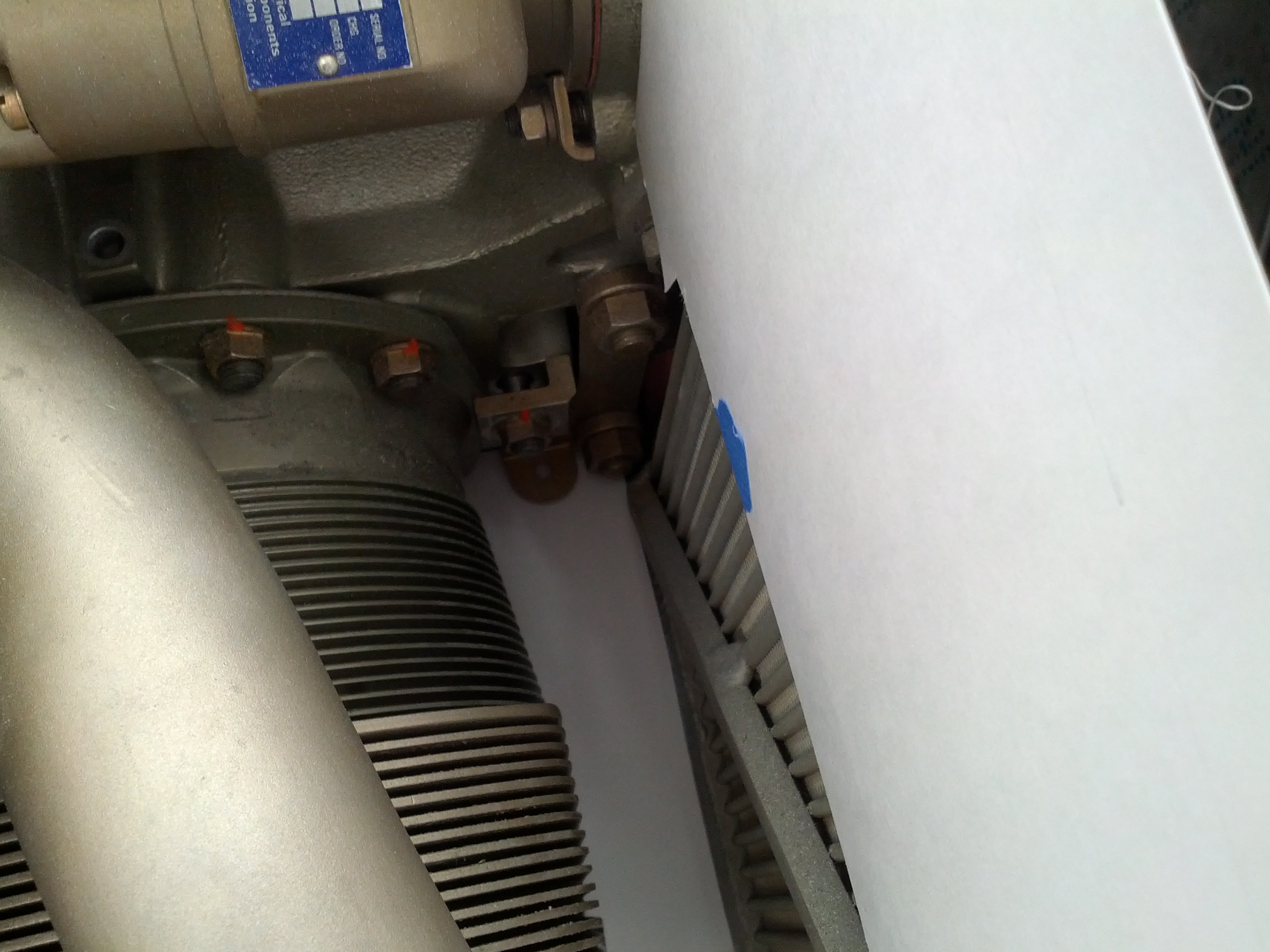
The area below the oil cooler was a real challenge (not much room).

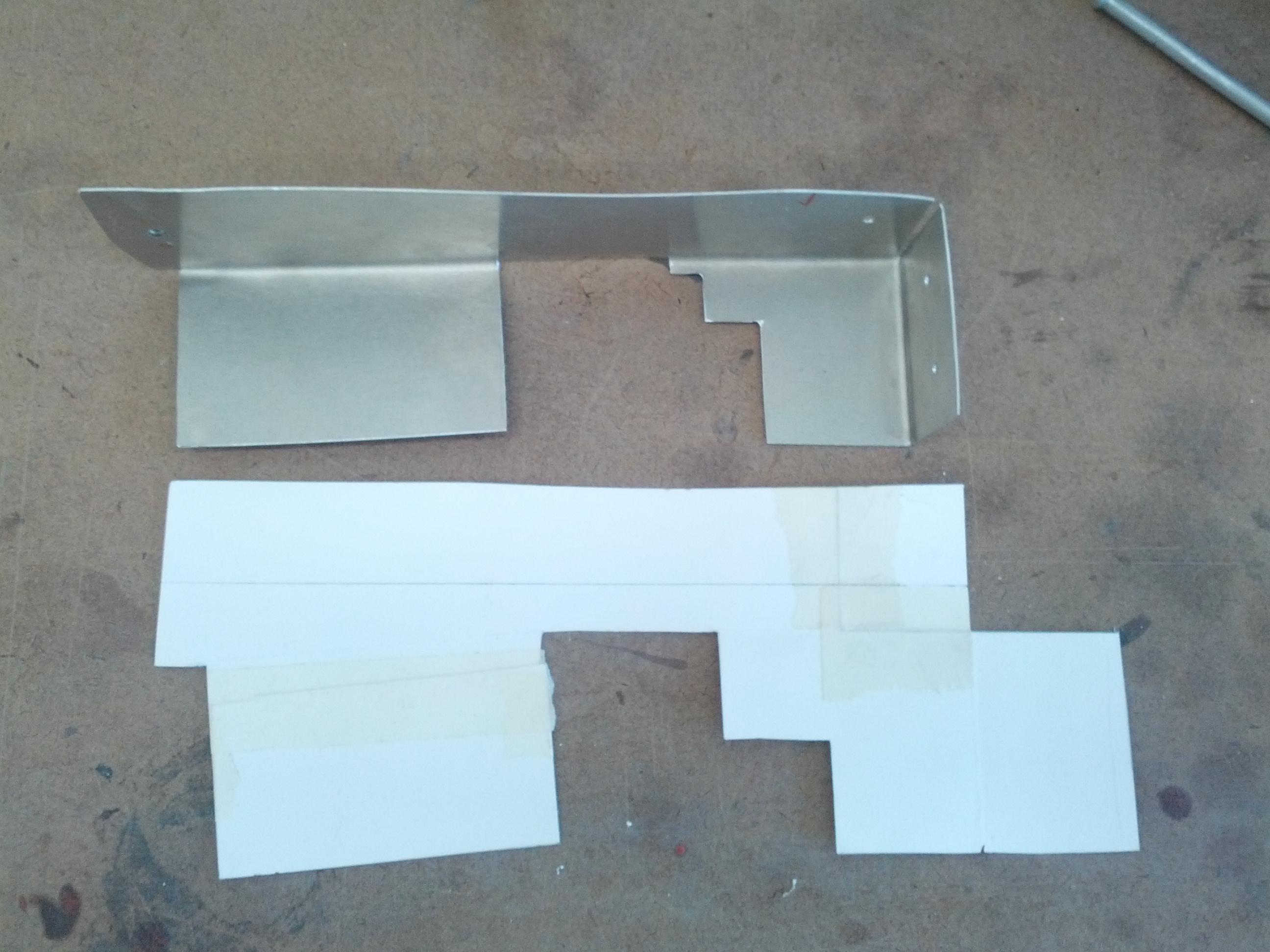
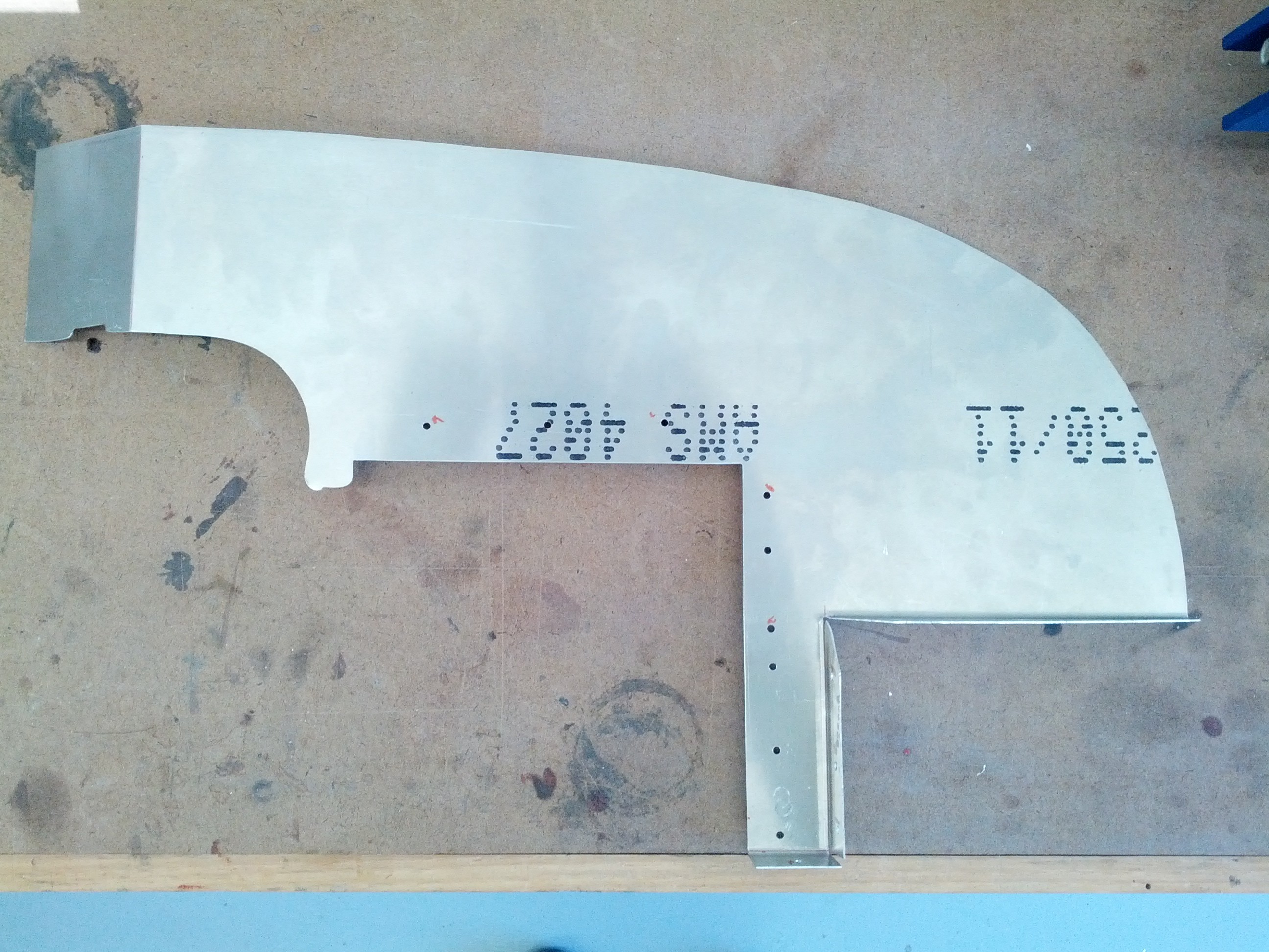
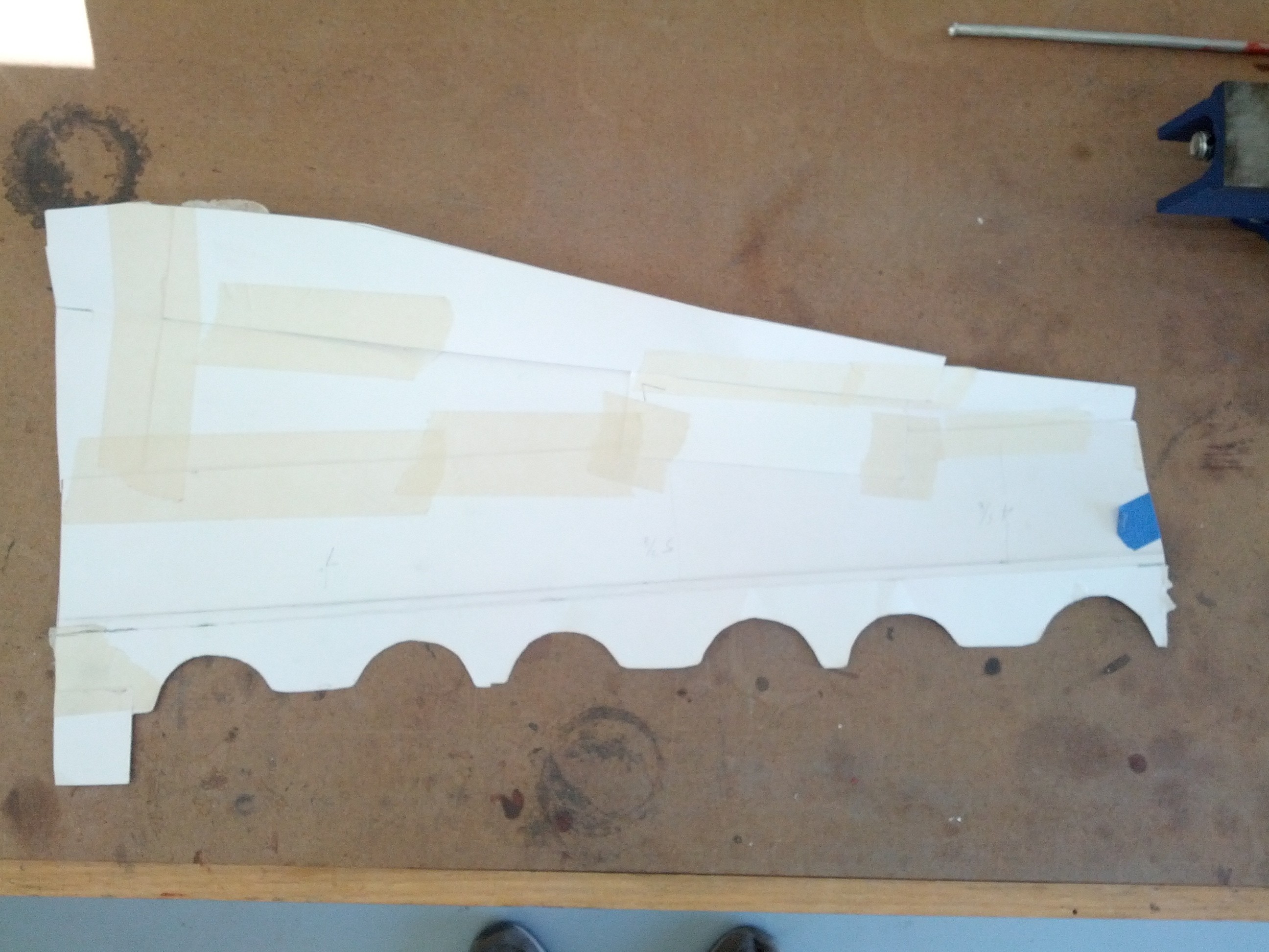
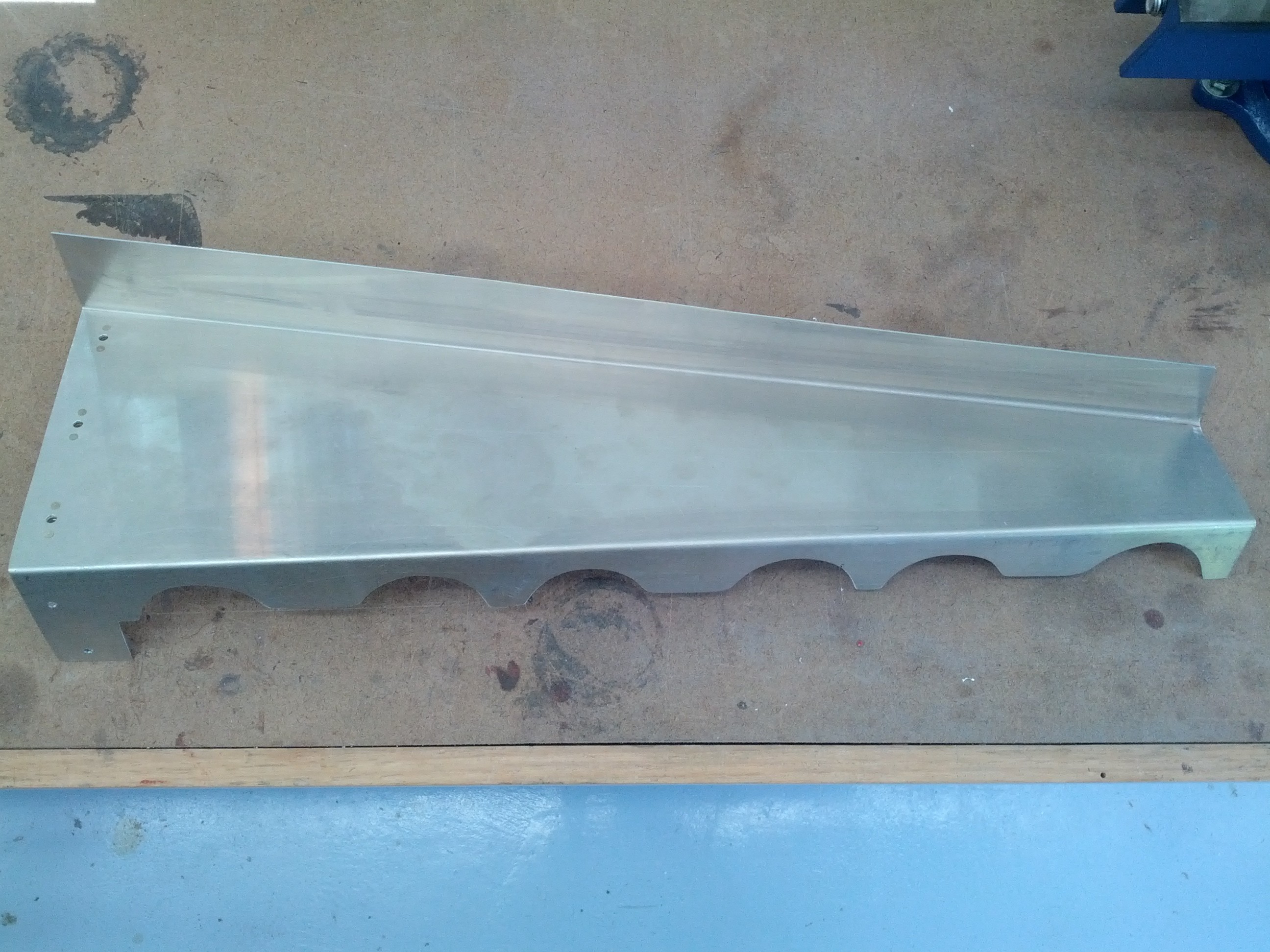
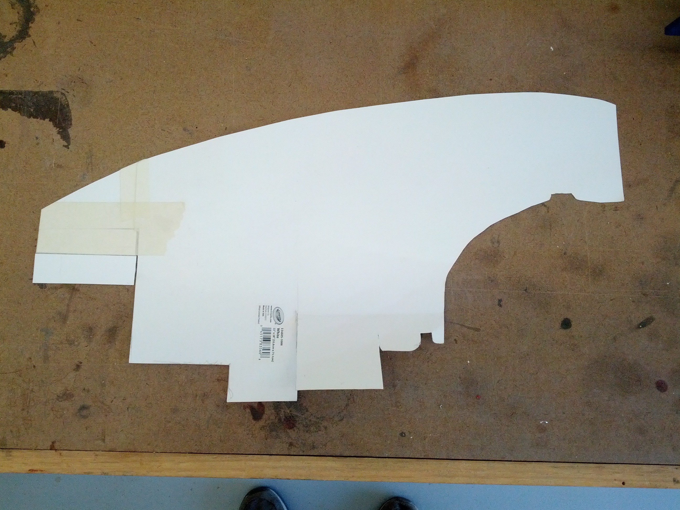
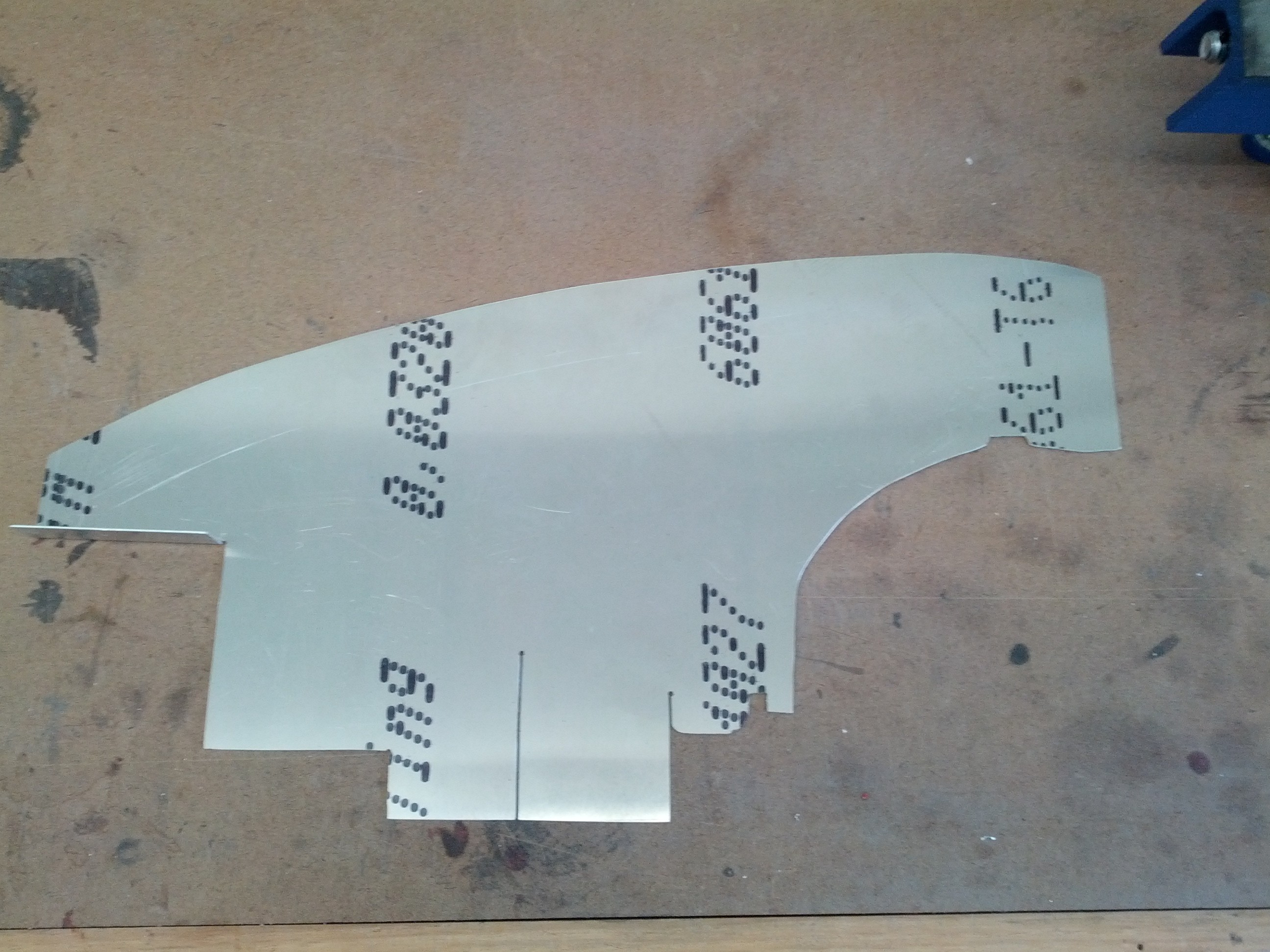
The pilot side was more of the same. snip a little, position, snip, position, snip, position, etc.Once I had all the paper templates, I transferred them to the aluminum and cut it out. After they were cut, Lynn let me use his brake so I could bend them where necessary.

Here’s the piece that goes between the oil cooler and the #1 cylinder.

The right front.

Right shelf.

Right rear.

Then I started putting all pieces in position (and trim some more) until they fit together and to the engine. Once I had everything fitting nicely, I began drilling and preparing to install the nutplates.

Here’s the final result. I don’t have all the attachment holes drilled just yet.

Next comes the brackets that attach the whole thing to the engine.

12.3.4 Cooling Plenum

This entry is part 24 of 50 in the series 12 - Engine / Propeller

The cooling plenum parts are fitting together quite well. So now I’ve got to get the whole thing attached to the engine. Each cylinder has a location to attach the side “decks”. First is to cutout and drill the pieces.

Then they have to be bent.

Then riveted to the decks and bolted to the engine.

Next are fore and aft brackets and a stiffener near the alternator.

12.3.4 Cooling Plenum Intakes

This entry is part 26 of 50 in the series 12 - Engine / Propeller

Now that the plenum is (mostly) complete, I need to get the cooling air into the plenum. In the normal installation, this is accomplished with NACA duct extensions.

I could use these extensions, but they would restrict access to the area between the engine and the firewall. So I decided (big surprise) to go a more traditional route. I created a pair of extensions that would permanently attach to the inside of the cowling. To build these I started with some foam that use formed to the desired dimensions. Then I covered them with a release agent (duct tape). Placed the forms on the inside of the cowling and covered them with a few layers of BID and a layer of Triax.

When they had cured, I trimmed them and created a lap joint where they would meet the rear of the NACA duct. Then I trimmed the forward wall of the plenum.

When it’s time, they will be bonded to the inside of the cowling.


12.1.2 Oil Cooler mod

This entry is part 22 of 50 in the series 12 - Engine / Propeller

While I was working on the baffling, I heard from another builder who mentioned that he had a problem with his oil cooler hitting the engine mount. He said that when the engine is starting and stopping that it moves a bit and had removed some of the paint from the engine mount. He caught it before is wore a hole in the oil cooler.

He had just less than 1/2″ clearance.

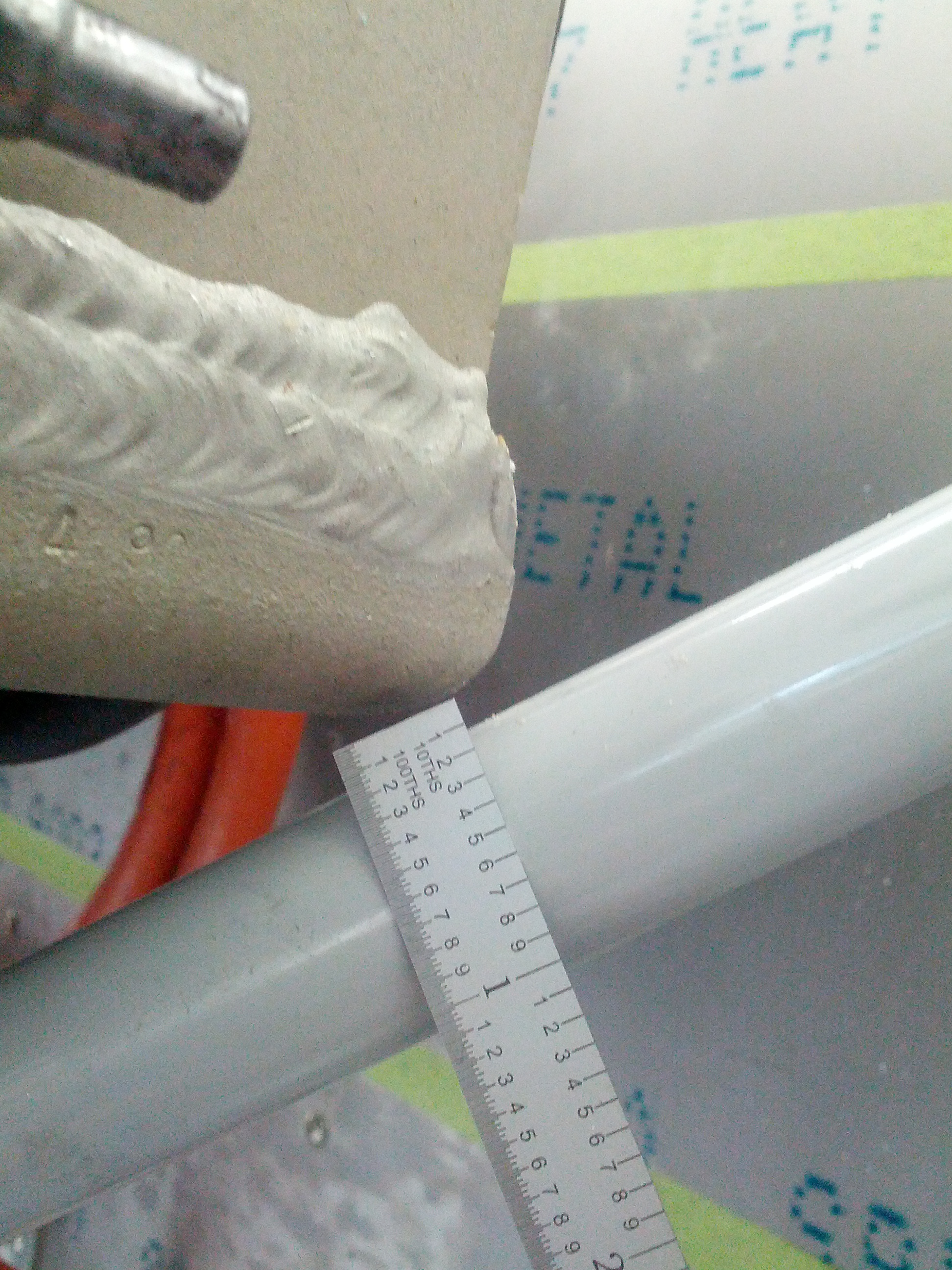
I decided to check mine and here’s what I found.

Not good. 🙁

I checked with the factory and they modified the engine mount a while back (before mine was made) to provide more clearance. They couldn’t figure out why I don’t have the proper clearance. They told me I could send back the mount and they would modify it but that would require removing the engine. I don’t have an engine hoist and doing it solo wouldn’t be fun. Plus, I didn’t know what other changes that modification would create.

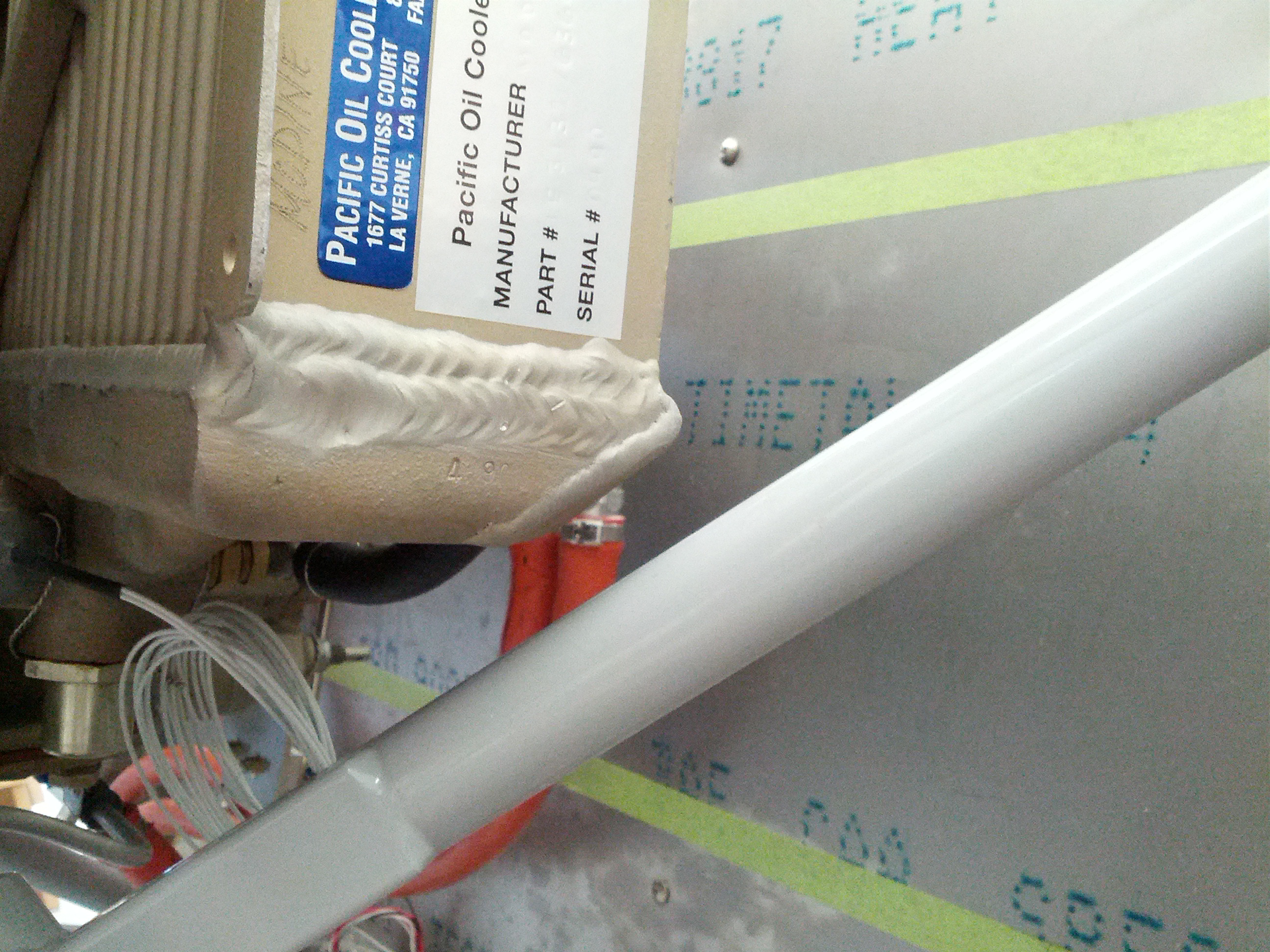
So I came up with plan B. I removed the oil cooler and sent it to Pacific Oil Cooler Services. Here’s the result:


12.2.4 Pressure lines

This entry is part 23 of 50 in the series 12 - Engine / Propeller

There are three pressure sensors that have to be installed. Fuel pressure, oil pressure and manifold air pressure (MAP). There’s also an oil temperature sensor but that’s installed on the oil cooler.

The rule is that you don’t install sensors directly on the engine. The vibration can cause them to crack or break and then you’ve got fuel or oil running all over the place.

There are a few different approaches to how the sensors are mounted.

One way is to mount the sensors to the firewall individually. Like this:

One of those is the fuel pressure sensor and the other is the oil pressure sensor. (I don’t have a picture that shows the MAP sensor.

But my buddy Brooke has his sensors consolidated.

On the left is the fuel pressure sensor, the right is the oil pressure and the center line connects to the MAP on the inside of the firewall.

This manifold was made from a piece of 3/4″ x 1″ x 5″ solid aluminum. I couldn’t find any 3/4″ x 1″ but I did find some 1″ x 1″  at McMaster-Carr (I love that place!).

Here’s my plan.

Here’s the 1 foot piece of aluminum that I bought.

I marked the location of the five holes on one edge (three for pressure and two for mounting).

I made a decision to move the fuel and oil feed lines from the side to the bottom. Here’s it is with the holes drilled.

And the finished product with cut down to 5 inches long with the holes taped and fittings & sensors installed.

Looking at it now, I should have put the MAP feed line on the bottom too. Since I’ve got enough stock left, I may make another with the three feed lines on the bottom.

Update…

I decided to see where I would mount this masterpiece. The three lines will all be coming from the right (co-pilot) side so that seems to be the logical location. But once I placed it on the firewall I noticed something.

This thing sticks WAY out. Which means that when I change the oil filter, it’s going to be in the way and in danger of getting bumped into.

I could try a vertical orientation. With the sensors on the top and feed lines on the bottom. But then I’ll still have to run the long feed lines all the way to the firewall.

Another method that I saw which I’m now giving serious consideration to is mounting the sensors to brackets that then mount on the engine with a short feed line. That way, instead of a couple 1/4″ feed lines going all the way to the firewall, I’ll only have four wires. Here’s an example that I found on a Cessna 350:

Still not sure how I’m going to resolve this.

12.2.4 Pressure Lines

This entry is part 25 of 50 in the series 12 - Engine / Propeller

After much thought and discussion, I’ve decided how I’m going to handle the pressure lines from the engine. Rather than have all of them go to a single manifold on the firewall, I’m going to route each of the three lines (fuel, oil & manifold air) independently.

For the Manifold Air Pressure, I’m going to simply use bulkhead fittings on the plenum and firewall and terminate it at the sensor inside the cabin. The oil pressure will be mounted on the fire near the oil cooler where the pressure line originates.

Oil pressure sensor mounted to firewall.

View from above.

For the fuel pressure sensor, I decided to mount the sensor inside the plenum. This will allow for a shorter pressure line and not require penetrating the plenum.

Because the manifold air pressure sensor is plastic, it has to go inside the cabin. So I’ll penetrate the plenum and firewall with bulkhead fittings.


12.3.4 NACA duct extensions

This entry is part 38 of 50 in the series 12 - Engine / Propeller

Prior to mounting the NACA duct extensions to the inside of the cowling, I placed the extensions in position between the NACA’s and the plenum. Then I installed the upper cowling and marked where the flanges of the extensions would be. I also drilled three holes through the cowling into the extension flanges. Then I removed the cowling and painted the inside of the cowl where the extensions would be along with the extensions.

Once the paint (actually, primer) was dry, I sanded the mating surface of the cowl and the flanges of the extensions. Then I applied structural adhesive to the flanges and mounted taped them to the NACA’s. The upper cowling was then mounted and cleco’s were used to hold the extensions to the cowling.

Once the adhesive had cured, I cleaned the inside of the extended duct and applied a radius of epoxy.

Finally, I used flush head pop-rivets and 1″ square titanium tabs as a mechanical fastener.

Looking back down the right NACA.