14.1.4 Aileron Balancing

This entry is part 15 of 38 in the series 14 - Final Assembly / FInishing

The balance of the aileron front-to-rear is important. Otherwise flutter can occur. First aileron is suspended from it’s hinge. The goal is that the aileron will rest in it’s natural position. Mine are a bit heavy at the trailing edge. This is normal. Lead weight that is used to balance automobile wheels is added to the front edge to change the balance.

I purchased some wheel weights at Harbor Freight a couple weeks ago. But when I opened them up today I noticed that they aren’t dull gray. Then I noticed the “Lead Free” sticker. So we went around to a few tire shops in the greater Greenville, SC area. It wasn’t until the third shop we stopped at before someone was willing to sell us the lead weights we needed (Thanks to Tire Exchange of Mauldin, SC).

Here you can see the locations for two rows of three strips of 3 ounce weights for a total of 18 ounces. We sanded around where the weights will be so that we can then cover them with a layer of BID.

This is the pilot side aileron. It was a little heavier and required an additional 3 ounces of weight for a total of 21 ounces.

After the veil and epoxy has cured.

14.1.4 Aileron Installation

This entry is part 16 of 38 in the series 14 - Final Assembly / FInishing

Now that the ailerons are balanced and the torque tubes are installed, it’s time to verify the motion of the ailerons. The openings in the wings that the torque tubes go through are sometimes… incorrectly defined. So now the ailerons are installed and they are moved through their range of motion. This revealed numerous binds.

So now the openings in the wings have to be made larger. Malcolm has a 5-foot long piece of 1″ electrical conduit that is covered with 36-grit sandpaper. It removes the foam but it’s only good going in about 3-feet before you lose leverage. And it can only go in from the outside.

So I can an idea. Since I wasn’t using the factory supplied aluminum aileron torque tube, I had this 12-foot long 3/4″ piece of tubing. So I slid Malcolm’s sanding tube over the longer tube. Then the whole thing is slid into the opening. While Malcolm held the inner tube at the engine compartment and arc’d the tube, I sanded away at the foam with the outer tube on the aileron end.

Here’s the sanding tube in position.

And here’s the view of the finished result.

It’s hard to get a good picture but the end result is that the aileron has unobstructed movement through it’s full range of motion.

14.2.3 Primer

This entry is part 17 of 38 in the series 14 - Final Assembly / FInishing

While I was cutting titanium, Malcolm was sanding rudders, doghouse cover and forward hatch cover.

When he was done, I decided to test something.

When we shot the final coat of primer, there were some… minor blemishes. Runs, basically. Not many, but a couple. Now when I was in high school, I worked at a body shop. In those days, if you screwed up and got a run in the primer, it was no big deal. You simply sanded the run out and then painted. But I’m not going to paint for at least a year. If the run occurred in the paint, then you sanded it out using very fine sandpaper. Depending on the paint, you may go as high as 1500 grit. Then buffed it out. I remember working on a 1972 911S Porsche. The owner wanted (and paid for) a hand rubbed lacquer finish. After painting, the entire car was hand sanded with progressively finer sandpaper and buffed out. The final result was incredible. It was like looking in a mirror.

I wanted to see if I could sand out the runs, and restore the shiny finish. So I brought down sandpaper grits from 400 up to 2000. To start, I only went up to 1000 grit. The finish was very smooth and somewhat glossy. Then I hit it with the buffer. The result was incredible.

And this is primer! 🙂

So now, whenever I get stuck, I’ll work on the runs and sags.

14.2.3 Final Prime of the Cowling

This entry is part 18 of 38 in the series 14 - Final Assembly / FInishing

Malcolm suggested waiting until later to do the final prime of the cowling because it can get banged up putting it on and taking it off. Since I’m moving the plane, I figured that I should get it done as I may not have the facilities where it’s going.

I did some final sanding and filling on the top and riveted the oil door and filled the rivet heads. Then set the cowling outside and sprayed. About an hour later a very isolated shower came through and put some big craters in the primer. 🙁

So the next day I sanded it down and primed it again.

2014-08-20 IMG_20140820_200129914 (Large)  2014-08-20 IMG_20140820_200102964 (Large)IMG_20140826_113755737 (Large)

On retrospect, I’m probably going to remove the oil door and use nutplates with flathead screws on the cowling side of the hinge. It’s just really difficult to get good coverage of paint under the door.

Back in the saddle again

This entry is part 19 of 38 in the series 14 - Final Assembly / FInishing

So after a number of false starts, it looks like I’m back.

There were some issues as to where the plane would end up.  But after 3 months, it looks like that’s resolved. So last Sunday I drove down (6.5 hours) to Sebastian from Panama City.  🙁

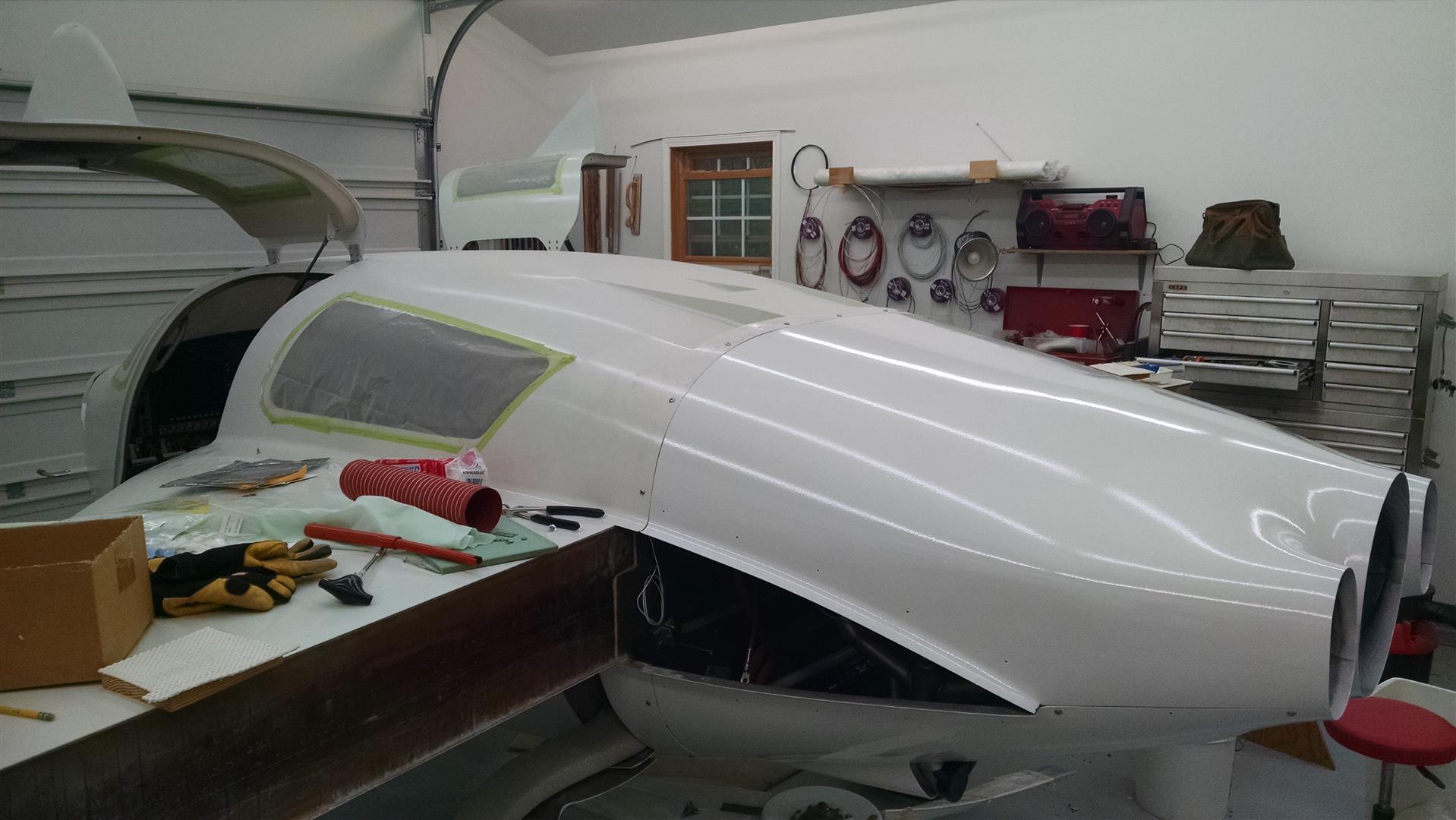
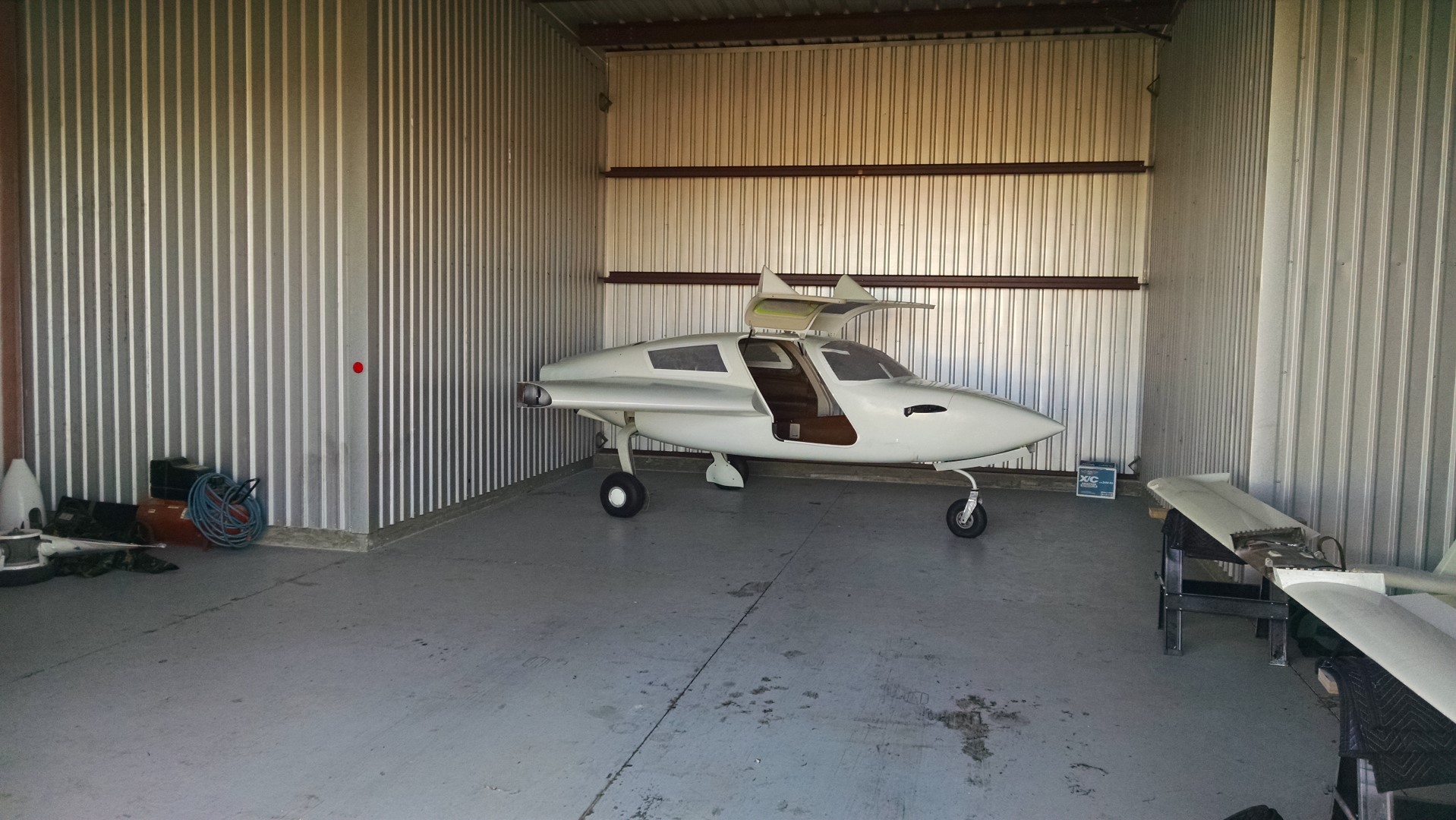
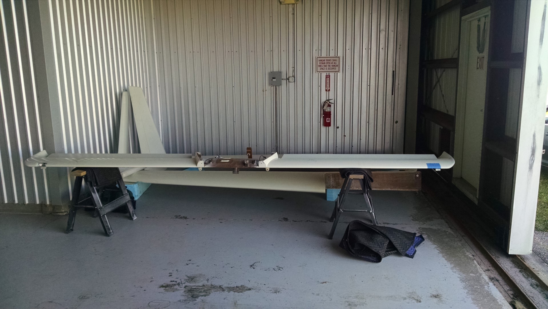
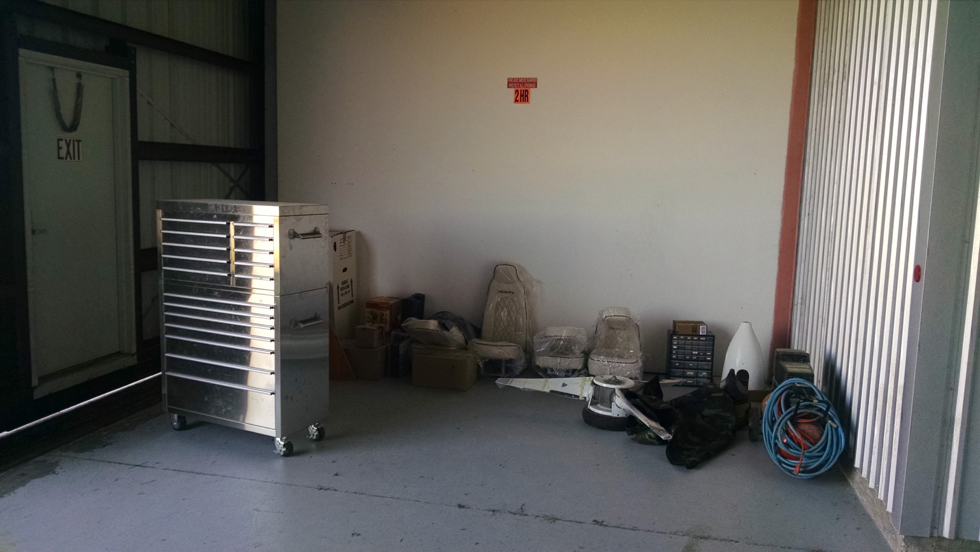
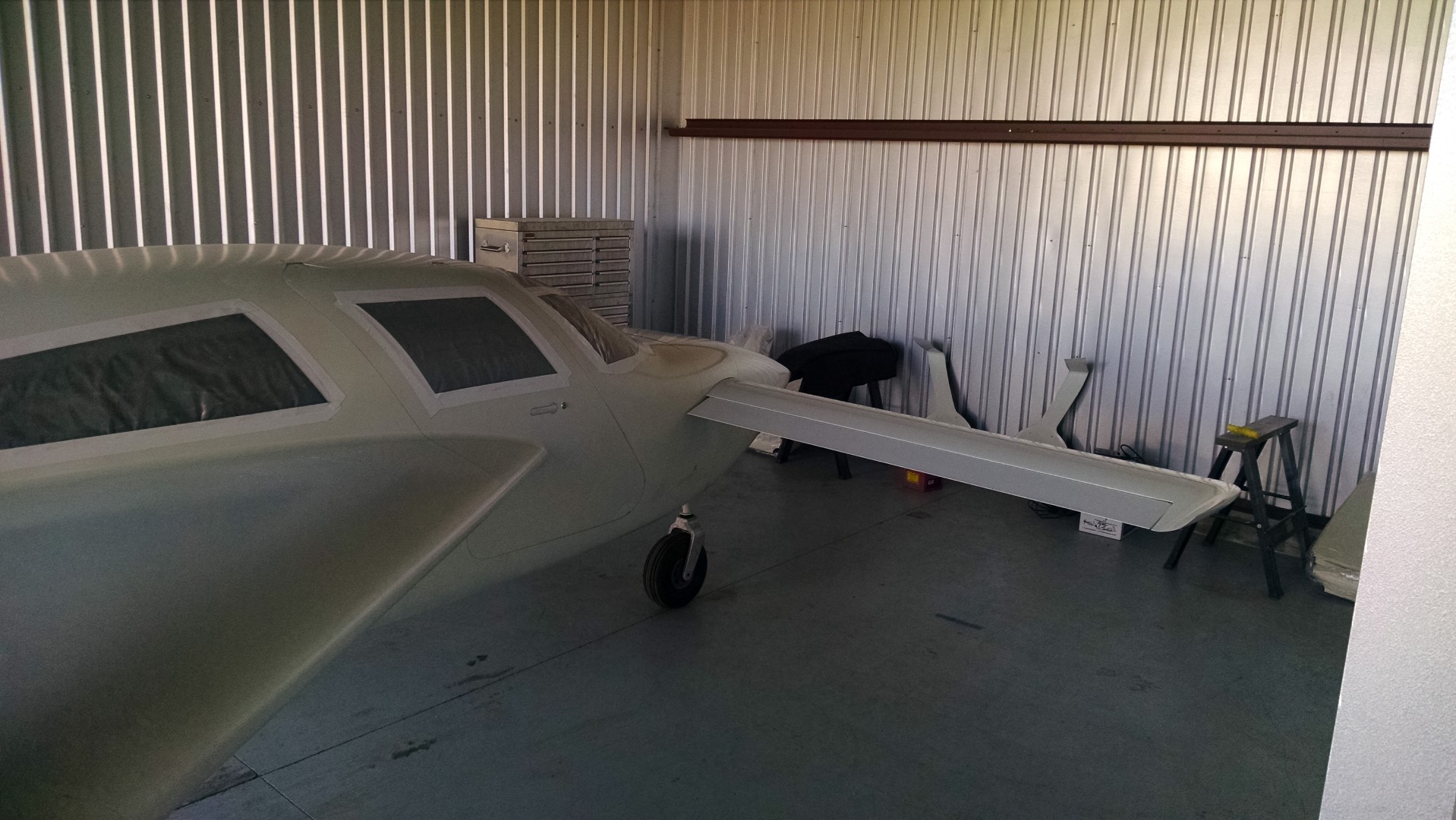
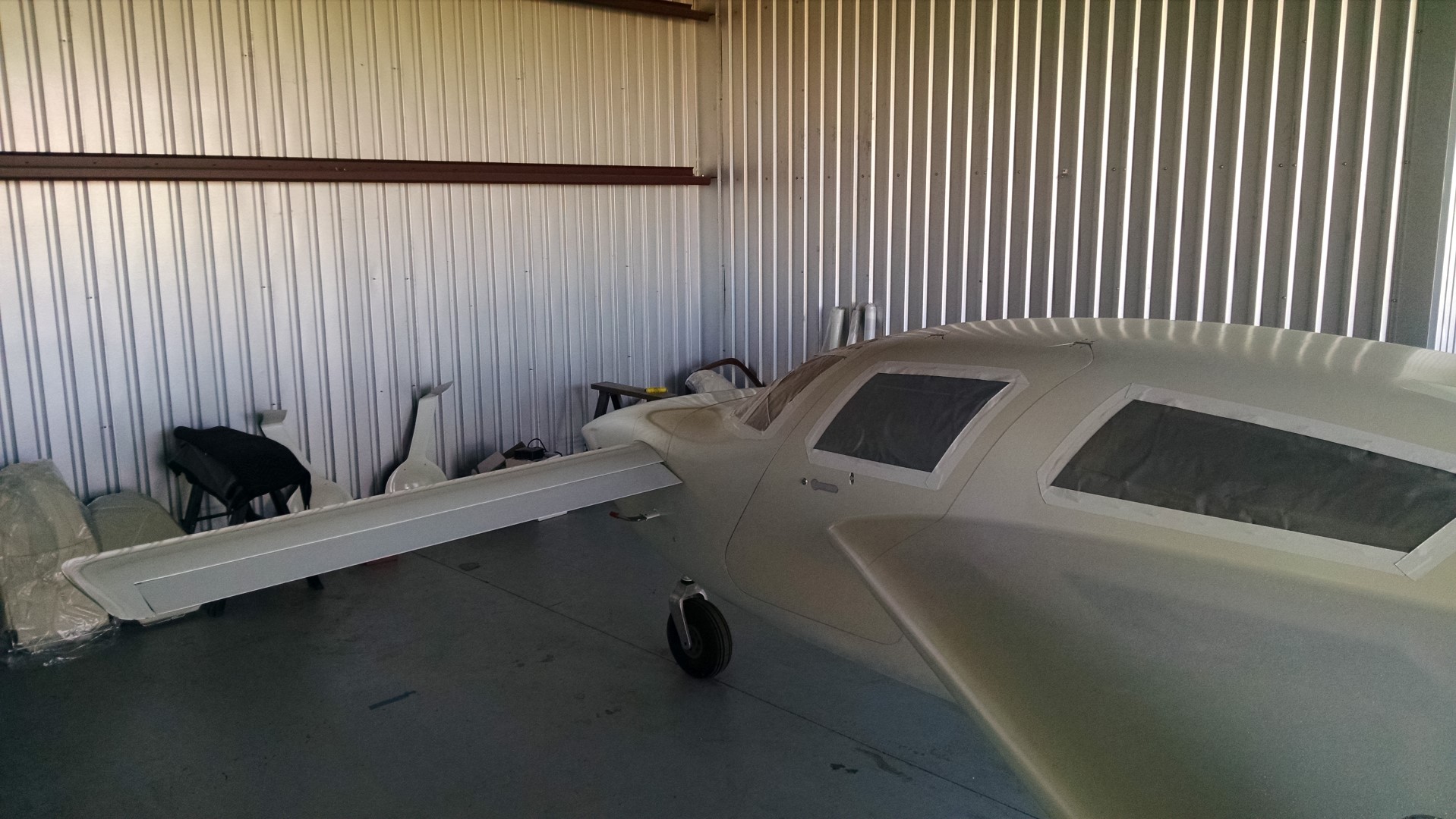
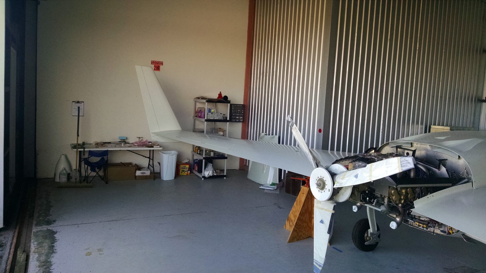
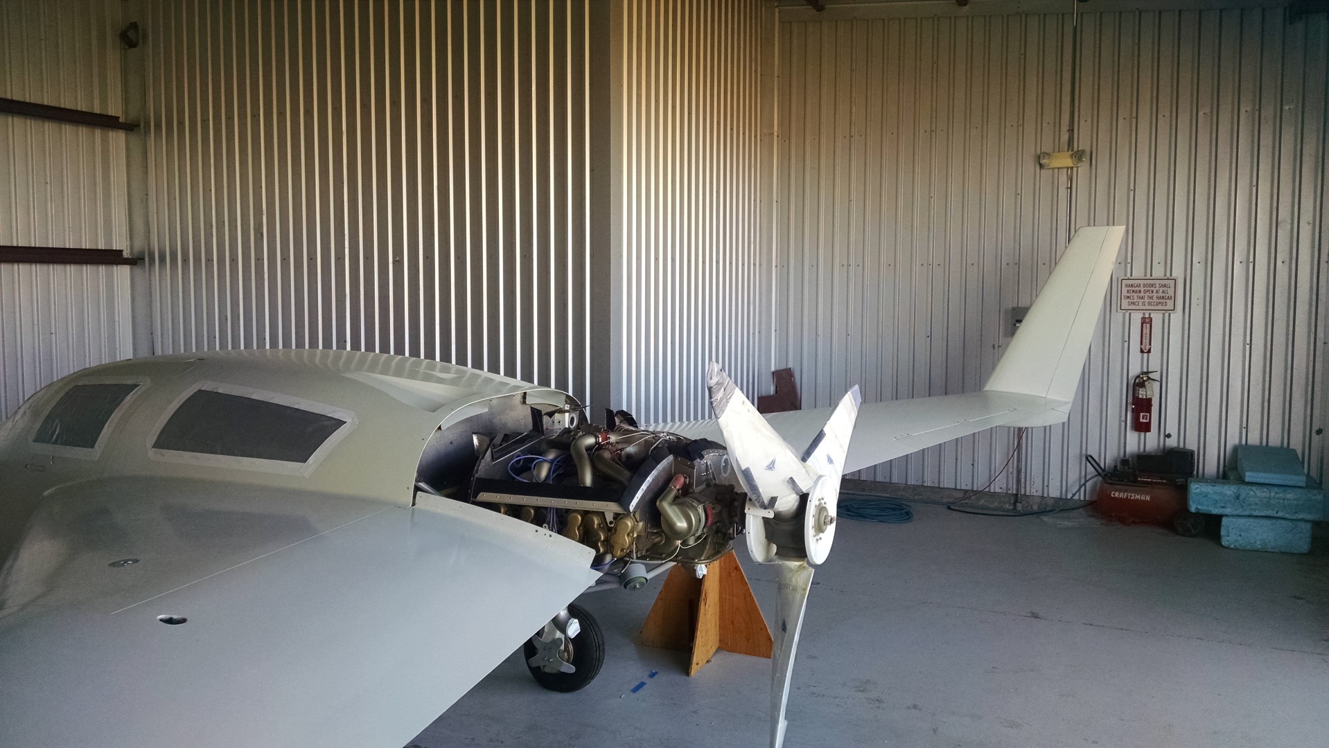
On Monday morning, I enlisted Malcolm (Who’s back down in Sebastian now) to help me get all the boxes of supplies, parts and tools moved into the new digs. Here’s the hangar with the plane that I really haven’t seen for 3 months.

2014-12-15 IMG_20141215_112829170 (Large) 2014-12-15 IMG_20141215_112838110 (Large) 2014-12-15 IMG_20141215_112851189 (Large)

Once everything was moved in, Malcolm started an inspection to create a “punch list” while I unpacked boxes. Within a couple of hours, he had two full pages of todo items. Most of those items (probably about 75%) involved replacing non-locking nuts with locking nuts.  During assembly, there is a lot of installing, removing, installing, removing… So in those circumstances, jam nuts are used since lock nuts can only be installed so many times before they have to be discarded.

So on Tuesday, we began in earnest to start checking off items from the list. By Thursday, we had most of the items done and it was time to install the prop and wings (permanently with locking hardware).  Before installing the wings, I had to mount the nav/strobe lights and terminate the wires for that and the nav/comm antennas.

2014-12-19 IMG_20141219_102511318 (Large)

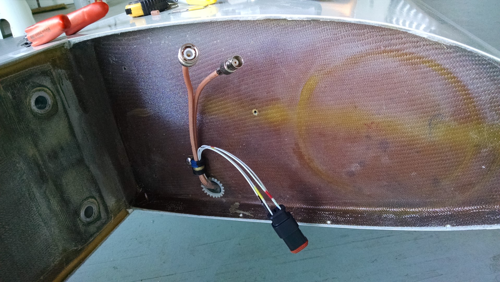
For the wingtip light wires, I used a nice weatherproof AMP connector and for the antenna wires, I used a male connector for the com and female for the nav.  That way there’s no way of mis-wiring the antenna wires.

On Thursday afternoon, we had the prop on.  By quitting time on Friday, the both wings were on and the punch list was much shorter.

2014-12-19 IMG_20141219_170901832 (Large) 2014-12-19 IMG_20141219_170840902 (Large)

2014-12-17 IMG_20141217_083024900 (Large)2014-12-17 IMG_20141217_083036202 (Large)

A lot of progress for the week, but now it’s time for another (hopefully shorter) hiatus. Christmas and then a week visiting our son in Montana.  Hopefully on the second week of January I’ll be back at it.

My plan is to find some type of transportation to leave in Sebastian so that I can fly the Cessna down.  It’s only 2 hours enroute that way as opposed to 6.5 hours.  I did some scouting but couldn’t find anything cheap.  So the next trip may be another drive. 🙁

Major items left to do are:

1) wheel alignment2) Connect all control surface links
3) Relocate audio panel


14.0 – Punchlist

This entry is part 20 of 38 in the series 14 - Final Assembly / FInishing

Making progress on Malcolm’s punchlist.

Fewer items than there were before.

2015-01-18 IMG_20141217_083024900 (Large) 2015-01-18 IMG_20141217_083036202 (Large)

Some of the items are pretty much done but since they aren’t “finished” I haven’t marked them off yet.  For example, the Vortalons, sparrow strainer and oil-door rework is pretty much complete.

Right now we’re working on the toe-in adjustment (AKA, wheel alignment) and it’s turning out to be very difficult.  We just can’t get a consistent setting.  Depending on the order the bolts are tightened, the measurement changes significantly.  It’s possible that the axles may have to come off and the gear leg gets re-worked. 🙁

Trip 2 completed

This entry is part 21 of 38 in the series 14 - Final Assembly / FInishing

All finished for this trip. Got a lot accomplished.  Battery installed, electrical systems tested, control systems connected, fuel shutoffs installed. Malcolm is finishing up the priming and painting of the sparrow strainer, vortilons and cowling.

Some final pictures as I was leaving.

2015-01-21 1204 IMG_20150121_120439715 (Large) 2015-01-21 1205 IMG_20150121_120505707 (Large)

2015-01-21 1205 IMG_20150121_120524959 (Large) 2015-01-21 1205 IMG_20150121_120534343 (Large)

And because I’m supposed to have pictures of me with the airplane…

2015-01-21 1205 IMG_20150121_120559241 (Large)

14.1.7 Vortilon Installation

This entry is part 30 of 38 in the series 14 - Final Assembly / FInishing

Vortilons are small tabs which extend forward from the leading edge of the wings. The word actually comes from two words: Vortex and Pylon. Here’s some aerodynamic science for you:

Vortilons officially first appeared when Douglas was developing the DC-9.  As is typically the case, rather than re-invent the wheel, previous technology and parts are used to speed up development.  In the case of the DC-9, Douglas engineers, decided to use the same wing design as the DC-8. The difference between the two is that the DC-8 had four engines under the wing (on pylons) where the DC-9 had them on the tail.

When they started testing, the engineers discovered that the wing had significantly less lift at low speeds (landing and takeoff) than the DC-8 wing. Since the only difference in the wing design (other than the engine location) were the pylons, they installed just the engine pylons under the wing.  And the lift returned! So the engineers made the pylons shorter and shorter until the lift diminished.

The result became what is now known as a vortilon.

What happens is with swept wing designs (although similar behavior can also occur on non-swept wings), as the angle of attach increases, the flow of air begins to move span-wise (toward the side) as opposed to chord-wise (front to rear).  One of the solutions is to install a fence.

Mig-17 with stall fences.

MiG-17F_Top_View

This prevents the air from moving towards the wingtip. The down-side to stall fences is that while they are only needed during high angles of attach (landing and takeoff), they incur a permanent drag penalty.  Anything sticking out creates drag.  And drag reduces speed.

Vortilons create a rotating spiral of air (vortex) that acts as a stall fence. But they are only doing this at high angles of attack. During low angles of attack, the vortilons aren’t doing much of anything.  Think of vortilons as stall fences that mostly retract when not in use.

Here’s a Starship (because, you know, they’re cool) where you can see four vortilons on the lower, leading edge of the wing.

0902020

The vortilons which come with the kit are rough fiberglass and about the same size. Because this is a highly visible, finish type part, I deferred it to the guru of all things finish (Malcolm).

Here is a picture of a set of vortilons (from Jorge Bujanda’s site) after being trimmed down.  The size goes from large to small as they go inboard to outboard.

vortilonsfinalshape

Then they have to be filled, primed, sanded, filled, primed and painted.

Vorts 4 Vorts 3

Now they do stick out a ways, so it would be real easy while working on the plane to run into one and break it off. So I’m not going to install them until I’m ready to fly. But the positioning is rather important. The location is easy to measure. Just measure out from the wingroot 18″, then 36″ more and then another 36″.  Getting them aligned is another story. For that Malcolm has a template he created.

2015-03-03 1443 IMG_20150303_144339010

First a mark is made on the leading edge. To get it perfectly on the leading edge, I kinda made a tool.

2015-03-03 1453 IMG_20150303_145310291

Then I placed the pencil against the leading edge with a level. While keeping the level/pencil perfectly plumb, I moved everything across the leading edge of the wing. The result is a perfectly straight line which is exactly on the leading edge of the wing.  Now I probably didn’t have to be that precise, but it wasn’t that hard.

Next the template is aligned with the mark on the leading edge and rolled under the wing.  Then simply mark the wing on that line.

2015-03-03 1448 IMG_20150303_1448591032015-03-03 1443 IMG_20150303_144355552

Now when it’s time to install the vortilons, I just have to line them up with the mark.


14.1.10 Calibrating Fuel Tanks

This entry is part 28 of 38 in the series 14 - Final Assembly / FInishing

This turned out to be a real pain.

I was expecting a relatively straight-forward process.  Something along the lines of add 5 gallons, press a button, repeat, etc.  That’s why I added the shut-off valves on the last trip.

Then I discovered that my fuel probes have five “setpoints” (Empty, 1/4, 1/2, 3/4 and Full). Which means that I have to fill the tanks to determine how much they hold, empty them, then refill while defining the setpoints.

So I removed the lines between the strake tanks and the sump, attached four feet of flexible line to the strake tank, ran the line out the main gear opening and attached the valve at the end. This way I can drain the tanks without too much fuss.

2015-03-03 1449 IMG_20150303_144958069

I borrowed eight 5 gallon fuel cans and had them filled at the FBO (I’ve been hoping for 45 gallons per side, but I didn’t want to get more fuel than necessary so I started with 40 gallons) Then carted them over to the hangar.

2015-03-04 1245 IMG_20150304_124539533

Then I started filling the tank and checking the level after each 5 gallons with my 12″ scale.

2015-03-04 1245 IMG_20150304_124557554

And 40 gallons just barely fit.  A bit disappointing since I was hoping for more capacity.  So I drained the fuel out… Which took about 7 minutes per 5 gallon can (so about 45 minutes to drain a tank). And that’s when I realized that the plane wasn’t level.  I had neglected to tighten the collar on the right jack and it leaked down so that the right wing was low. I raised the jack until the plane was level and then moved over to the left side. After putting in all 40 gallons, I still had about 1/2″ left. So back to the factory to borrow another 5 gallon can, over to the FBO to get it filled, back to the hangar and poured it in the left tank. It didn’t take much before it was full but it looks like just shy of 42 gallons.

Then I drained out the fuel and refilled defining the fuel probe setpoints with “Empty” at 2 gallons, 1/4 at 10 gallons, 1/2 at 20 gallons, 3/4 at 30 gallons and “Full” at 41 gallons (although the probe looks at anything over about 35 or so as full).

Then I drained the left tank and refilled the right defining the setpoints the same as the left side. When I was finished, I determined the right tank holds just a little more than 41 gallons.  So I decided to call the fuel tanks at 41 gallons.

Then I drained the right tank (for the last time), reconnected the strake to sump fuel lines and dumped the fuel back in. After a short period the fuel equalized between the two tanks and I was done with th  at task.


14.99 Contact!

This entry is part 29 of 38 in the series 14 - Final Assembly / FInishing

So at this point, the wheels have been aligned, the fuel tanks have fuel in them, the electrical system is complete. In short, there’s nothing that needs to be done to start the engine.

So I drained the oil down to 8 quarts (I had overfilled it as part of the long-term storage), pulled the upper (desiccant) plugs and removed the covers from the exhaust and intake.

Malcolm came over to act as a pair of eye watching the engine for any problems (with the engine in back, you can’t see it from the cockpit). We pushed the airplane out of the hangar and with the mags off, I cranked the engine for about 5 seconds to get oil circulated.

Then I installed and connected the upper spark plugs, looked things over one last time and hopped in. Malcolm was positioned just by the left wing with the fire extinguisher (just in case). I primed the engine and Malcolm say fuel coming from the bottom of the engine. We looked things over and discovered the fuel supply fitting at the forward baffle was loose. Considering all the fuel fittings, I’m surprised that I only missed one.

I tightened it and tried priming the engine again. No leaks this time.

Then I turned the left mag on a cranked the engine. It tried to catch but never really started. Malcolm noticed that only one side seemed to be firing. Tried a couple more times and it finally caught and started. But it was rough. And it stalled out after about 10 seconds.  I noticed that the EGT for the #4 cylinder was non-existent. So I guessed that the bottom plug had gotten fouled due to oil getting into the cylinder from being overfilled.  When I went to remove the ignition wire, I discovered it was loose. When I checked the other lower plugs, they were all loose. However long ago that I had built the baffling and removed and reinstalled the ignition wires to route them through the baffle, I never tightened them.

So a few minutes later, they were all tight.

Back in the cockpit, and it started right up.

Run #1

2015-03-06 1632 Image00512015-03-06 1633 Image00522015-03-06 1633 Image0053

I ran the engine for about 10 minutes until the oil got up to about 320 degrees and the EGTs all came up. I noticed that the #4 EGT was still reading zero. The CHT was reading about the same as the other 5 cylinders so I knew it was making power. Once I shut down the engine, a quick check with the IR thermometer showed the same temp and the other cylinders. So it had to be a loose connection or a bad EGT probe.

But it was late and it’s always good to leave on a high note. So we put the plane back in the hangar.

The next morning, I replaced the connectors for the #4 EGT probe and we pushed it back out for run #2.

Run #2

2015-03-07 1533 Image0056 2015-03-07 1534 Image0057 2015-03-07 1531 Image0054 2015-03-07 1531 Image0055

Engine started right up.  But it’s still not quite right. I called my A&P/IA friend and he said that it was probably going to need to adjust the fuel injection system. Even though the engine shop ran the engine after rebuilding it and would have adjusted it, he said that it’s not unusual to have to do again. So that will happen on the next trip down.